

Page 1
Page 2
Page 3
1 ALUMINIUM ELECTROLYTIC CAPACITORS
INCAP
ABOUT OUR COMPANY
INCAP LIMITED
ISO 9001:2000 accredition is managed by professionally
qualified personnel. The compan y with sound financial
discipline, is having its registered office and
manufacturing facility located at Nidamanur village which
is 12 K.M. away from Vijayawada on N.H. 5 and is
accessible by road and rail from different parts of the
country. The company has got an installed capacity of
100 million pcs per annum and was established in the
year 1992 with technical and financial collaboration from
M/s. Lelon Electronics Corporation.
a Public Limited Company with
PLANT AND MACHINERY
The Plant is housed in 2.5 acres of land with clean and
green atmosphere. We also ensure that the process
followed and waste disposable actions are
environmental friendly. Machinery which are imported
from Japan and Taiwan are maintained with meticulous
care to ensure improved productivity of quality products.
The performance of the Machine is closely monitored
by the team responsible for Maintenance and Production
by analysing the percentage yield on weekly basis and
making further improvements in the yield by going for
innovative techniques.
ABOUT THE PROCESS
All products are processed in a controlled and dust free
environment where Temperature, Relativ e humidity and
Human comfort are maintained at the optimum level.
The operators are provided with uniform and it is made
compulsory to use chlorine free gloves while handling
the products till it is hermetically sealed. We have
provided Air curtains at the entry to the plant to keep a
barrier from outside atmosphere and also to prevent
dust coming inside the plant. Operators are trained
specific to the nature of the work carried out including
the setting precautions and the quality norms so that
production is never taken on deviation. Besides, petrol
inspector collects samples at regular intervals from all
stages of production to see its conformance to the set
quality norms.
PRODUCT RANGE
Our product range covers Radial capacitors of
Low V oltage (850C and 1050C.)
0
Medium & High voltage (85
Low Leakage
Long Life & Extended Long Life
0
Low ESR (85
Bi-Polar
Non-Polar etc.
Our Snap-In type capacitors and Lug type capacitors
cover a range of capacitance upto 10,000 uF and a
voltage range upto 500 WV. We have satisfactorily
developed 105
up to 450WV and are being regularly supplied to OEM's
and Dealers.
C and 1050C.)
0
C special type Snap-in type capacitors
New Addition to the product range :
I) Radial Capacitors :
a) Specially designed capacitors for Electronic
Ballast and other Lighting Applications
b) Import substitute capacitors with DO T approval.
II) Motor Start Capacitors :
a) 230 V AC Motor Start Capacitors (Single Can
and Double Can) for local requirement of single
phase pump sets, air conditioners, wet grinders
etc.,
b) 110 V AC, 125 V AC , 140 V AC and 150 V AC
single can Motor Start Capacitors meant for
export to Singapore, Taiwan, Mexico etc.,
III) LUG Terminal Capacitors :
Starting from 25 diameter to 45 diameter covering
a range of very high CV values in Low Voltage,
Medium and High Voltages.
IV) Professional Screw Terminal Capacitors :
Starting from 35 diameter to 76 diameter covering
a wide range of CV values including high voltage
up to 500 WV.
C and 1050C.)
Design, specifications are subject to change without notice.
Page 4
2 ALUMINIUM ELECTROLYTIC CAPACITORS
INCAP
QUALITY ASSURANCE
Materials are sourced from quality suppliers of repute
from different parts of the world such as Japan, France,
Italy, Korea and Taiwan based on the specification
provided by us. Incoming Inspection department verify
the quality with respect to the specification and Raw
Materials and Components strictly confirming to the
specifications are accepted.
All though the finished products are 100% tested in the
automatic / semi automatic machines in the production,
our Final Inspection Department take random samples
as per Incap standards which are inline with International
standards and record the observations and sends a
copy of the same to customers for ver ification as an
objective evidence of the conf ormance to the set quality
levels.
Reliability of any product depends upon the availability
of proper testing apparatus and instruments. Our
instruments are calibrated at periodic interv als and are
maintained well to prevent the non confirming products
going into the market. We are committed to provide
quality product and service at competitive prices at all
times.
This may be the obvious reason that most of the major
OEM's and other buyers started using our product on
DOL (DIRECT ON LINE) basis.
We strongly believ e that right selection of the materials
and its proper processing with quality checks at different
stages of the process shall contribute to cost
effectiveness and PPM lev el quality of the end product.
R&D ACTIVITY
"Customer is the Key to our Progress" and we
give utmost importance to the customer feed back
regarding Quality, Delivery, Service and Cost. In order
to maintain leadership in quality and service, we always
analyse competitors product and also the customers
input by a comparative evaluation techinique and the
generated data is used for continuous improvement of
our products in line with the changing demand of the
actual user. This implies that we make what customers
need and supply them to their satisfaction.
R & D Department collects samples of finished products
at different intervals and subject them for different tests
as per National and International Standards applicable
for Aluminium Electrolytic Capacitors.
Our R & D efforts in nut shell
"Boosting the
productivity and performance of the products
while cutting costs"
APPROVALS
1) Systems Approval: ISO 9001:2000
2) Product Approval : LCSO, CACT and C-DOT
3) Approvals from MNCs as per their specifications
TRAINING
We firmly believe that continuous training of emplo yees
shall only contribute to improved quality with consistency .
With this view in mind we organize training program to
our employees which are specifically needed to carry
out the work in an effective manner. This type of
awareness creation coupled with the infor mation on
customer feed back improves the mindset of the
employees about the changing market requirements and
quality which act as an incentive to produce better quality
products.
WORK CULTURE
Our employees are the greatest resources to our
Company and we see that this resource is growing in
positive direction by imparting training on stress relieving
and motivate them to take up larger initiatives and to
work with dedication and team spirit. Employees
providing ideas and suggestions are suitably rewarded
which shall promote the generation of innovative ideas.
RELIABILITY and INTEGRITY are the corner
stones of our services and this structutre is serving our
customers excellently for several years now. It is our
constant endeavor at INCAP to provide quality product
and work towards
"Customer delight".
Design, specifications are subject to change without notice.
Page 5
3 ALUMINIUM ELECTROLYTIC CAPACITORS
GENERAL INFORMATION
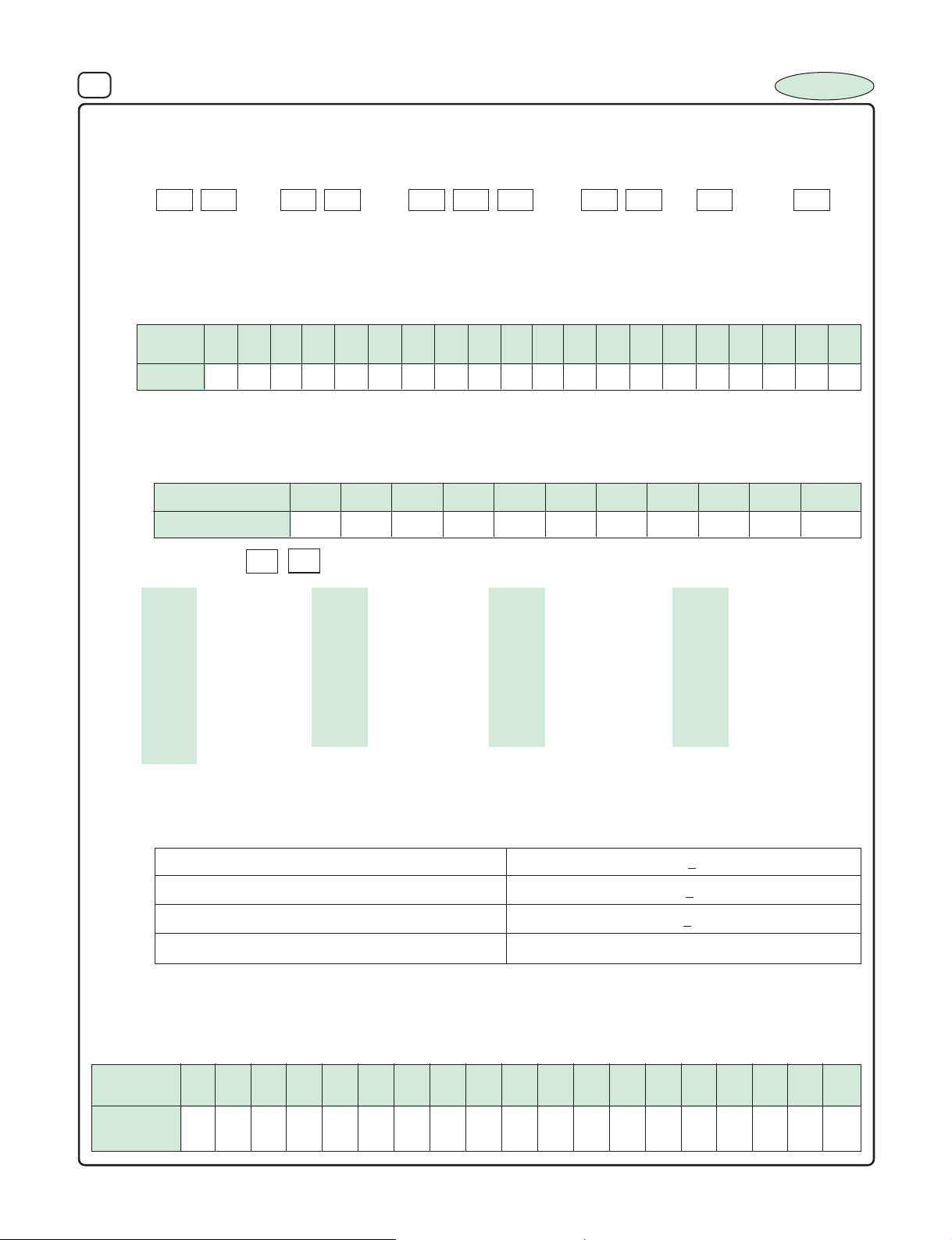
1. HOW T O ORDER
SERIES RATED VOLTAGE CAPACITANCE SIZE PACKING TOLERANCE
a) SERIES : Refer Table of Contents.
b) RA TED VOLTAGE :
Voltage in volts (V) is represented by a two digit code showing the real working voltage indicated as follows.
INCAP
Voltage
(WV)
Code
c) CAPACITANCE :
Rated capacitance in uF is represented by a three digit number. The first two digits are the significant figures of the
nominal capacitance and the third digit indicates the number of zeros following these figures. The decimal point is
represented by the capital letter R. Please refer to the following example
d) SIZE : EX. : 1 2 = 5 x 11
5x11 - 12 6.3x11 - 13 8x11 - 14 10x13 - 15
10x16 - 16 10x20 - 17 10x25 - 18 13x21 - 19
13x25 - 20 16x16 - 21 16x25 - 22 16x32 - 23
16x36 - 24 18x32 - 25 18x37 - 26 18x43 - 27
22x37 - 28 22x43 - 29 25x25 - 30 25x30 - 31
25x40 - 32 25x50 - 33 25x60 - 34 25x64 - 35
30x35 - 36 30x40 - 37 30x50 - 38 35x30 - 39
35x35 - 40 35x45 - 41 35x52 - 42 35x60 - 43
35x63 - 44 35x68 - 45 40x40 - 46 40x50 - 47
40x63 - 48
e) PACKING : B - Bulk T - Tape
f) TOLERANCE :
Symbol of W, T, Q, V, M, K and J show special capacitance tolerance which are listed as follows.
4
6.3 10 16 25 35 40 50 63 100 160 200 250 350 400 450
OG
OJ 1A 1C 1E 1V 1G 1H 1J 2A 2C 2D 2E 2V 2G 2W
µF
Part Number
13
1B
0.1
OR1
0.47
R47
1.0
010
4.7
4R7
751K80
1L
100
1001047047101
470
471
1000
102
4700
472
500
2X
10000
103
W = -10~ + 100% M = + 20%
T = -10~ + 50% K = + 10%
Q = 10~ + 30% J = + 5%
V = 10~ + 20%
2. SURGE VOLTAGE :
The surge voltage rating is the maximum DC over-voltage to which the capacitors may be subjected of short periods not
exceeding approximately 30 seeconds at infrequent intervals of not more than five minutes.
Unless otherwise specified, the rated surge voltage of the electrolytic capacitors are as follows :
Rated
Voltage (V)
Surge
V oltage (V)
6.3 10 13 16 25 35 40 50 63 75 80 100 160 200 250 350 400 450 500
8 13 16 20 32 44 50 63 79 90 100 125 200 250 300 400 450 500 550
Page 6
4 ALUMINIUM ELECTROLYTIC CAPACITORS
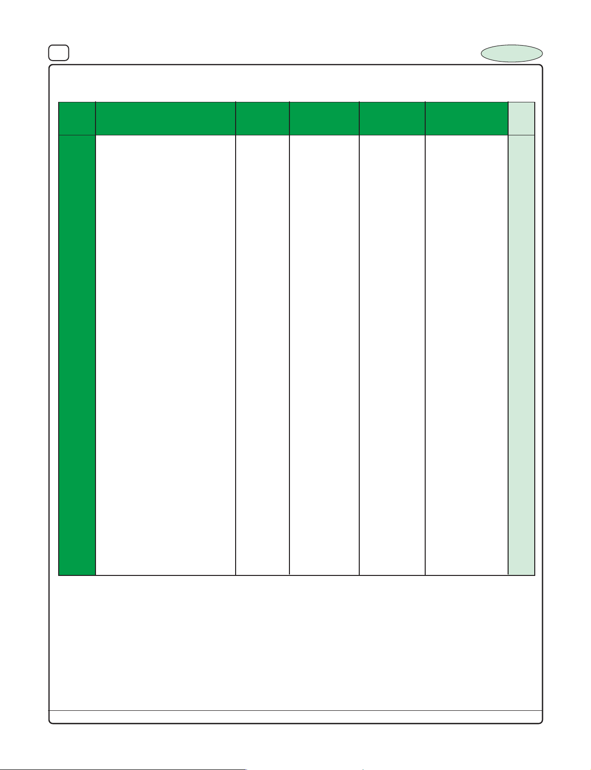
TABLE OF CONTENTS
INCAP
SERIES
IG
IT
IH1
IH2
BP1
NP1
NP2
IE1
IE2
LL1
LL2
IL1
IL2
IL5
VOLTAGE
FEATURES
General Purpose 850C 6.3 to 100 –400C to +850C 0.1 to 22,000 2000 hrs at 850C7
General Purpose 1050C 6.3 to 100 –400C to +1050C 0.1 to 10,000 2000 hrs at 1050C9
Medium & High Voltage 850C 160 to 450 –400C to +850C 0.47 to 330 2000 hrs at 850C11
Medium & High Voltage 1050C 160 to 450 –400C to +1050C 0.47 to 220 2000 hrs at 1050C13
Bi-Polar 25 to 100 –400C to +850C 1.5 to 10 2000 hrs at 850C15
Non-Polar 6.3 to 100 –400C to +850C 0.47 to 2200 2000 hrs at 850C17
Non-Polar 6.3 to 100 –400C to +1050C 0.47 to 2200 1000 hrs at 1050C19
Low ESR 850C 6.3 to 160 –400C to +850C 1 to 10,000 2000 hrs at 850C21
Low ESR 1050C 6.3 to 160 –400C to +1050C 1 to 10,000 1000 hrs at 1050C23
Low Leakage 850C 6.3 to 100 –400C to +850C 0.1 to 4700 2000 hrs at 850C25
Low Leakage 1050C 6.3 to 100 –400C to +1050C 0.1 to 4700 1000 hrs at 1050C27
Ballast Application 850C (Long Life) 250 to 450 –400C to +850C 3.3 to 47 2000 hrs at 850C29
Ballast Application 1050C (Long Life) 250 to 500 –400C to +1050C 3.3 to 100 2000 hrs at 1050C30
Ballast Application 1050C 350 to 450 –400C to +1050C 3.3 to 10 5000 hrs at 1050C31
RANGE
(Vdc)
OPERATING
TEMPERATURE
RANGE
CAPACITANCE
RANGE
(µF)
LOAD LIFE
Page
No.
(Extended Long Life)
Taping Specification 32
IS1
IS2
TUB 5
IS2-4T
LT1
MS1
MS2
ST1-G
Note :
1. Contact Factory for miniaturised 500 V DC Radial, Snap-In type Capacitors.
2. LA1, LA2 Ser ies Capacitors are replaced with high reliability IL1, IL2 series of capacitors.
3. New Products developed :
a) 3 Terminal Capacitors - TUB 5
b) 4 Terminal Capacitors - IS2-4T
c) -55
Snap-in 850C 25 to 450 –250C to +850C 47 to 15000 2000 hrs at 850C33
Snap-in 1050C 25 to 450 –250C to +1050C 47 to 15000 1000 hrs at 1050C35
Invertor and Convertor Application 1050C 10 to 100 -550C to + 1050C 180 to 15000 5000 hrs at 1050C
Invertor and Convertor Application 1050C 25 to 100 -400C to +1050C 4000 to 56000 2000 hrs at 1050C
Lug Terminal 850C 25 to 450 –400C to +850C 470 to 33000 1000 hrs at 850C41
Motor Start (Double Can) 230v AC –300C to +700C
Motor Start (Single Can) 230v AC –300C to +700C As per IS 2993 43
Screw Terminal 850C 16-450 –400C to +850C 1000-100000 1000 hrs at 850C44
0
C to +1050C Capacitors of 63 WV and below
40–60 to 200–250
37
39
As per IS 2993 43
Refer our Screw Terminal Capacitor catalogue for Professional Grade series of Capacitors
Design, specifications are subject to change without notice.
Page 7
5 ALUMINIUM ELECTROLYTIC CAPACITORS
INCAP
APPLICATION GUIDELINES
1. Circuit Design
Ensure that operational and mounting Guidelines specified in the
Catalogue and Data Sheets are followed while using Aluminium
Electrolytic Capacitors.
1.1 Operating Temperature and Frequency
Electrical Parameters of Electrolytic Capacitors are normally
specified at 20
parameters vary with changes in temperature and frequency.
Circuit designers should take these changes into consideration
while designing the circuit.
0
C temperature and 120Hz frequency. These
1.1.1 Effect of operating temperature on electrical parameters
a) At higher temperature, Leakage Current and Capacitance
increases while Equivalent Series Resistance (ESR)
decreases.
b) At lower temperature, Leaka ge Current and Capacitance
decreases while Equivalent Series Resistance (ESR)
increases.
1.1.2 Effects of frequency on electrical parameters
a) At higher frequencies, Capacitance and Impedance decrease
while tan d increase.
At lower frequencies, Ripple Current Generated Heat will rise due
b)
to an increase in Equivalent Series Resistance (ESR).
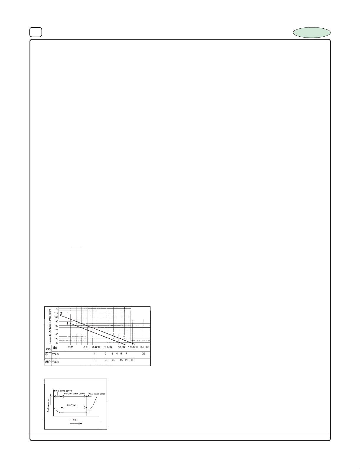
1.2. Operating Temperature and Life Expectancy in accordence with
usefull life of Capacitance
1.2.1. Life is affected by the increase in temperature. Generally, each
1.2.2. If operating conditions exceed the maximum rated limit, the
The useful life of Capacitor at maximum operating temperature is
as follows.
0
C a rise in temperature will reduce the useful life by 50%. Use
10
capacitors at the lowest possible temperature below the maximum
rated temperature to get optimum specified results.
electrical parameters deteriorate rapidly causing irreversible
damage to the capacitors.
Check for maximum capacitor operating temperature including
ambient temperature, internal capacitor temperature rise due to
ripple current and the effect of radiated heat from power source.
T
- T
1
2
2
L
=L1 x 2 where,
1
L
: Specified life (hrs) at temperature, T
L2: Useful life (hrs) at temperature, T
1
T
: Maximum operating temperature (0C)
2
T
: Actual operating temperature, [ambient Temperature +
10
0
1
C
0
2
C
Temperature rise due to r ipple current heating (
0
C)]
A quick reference capacitor guide for estimating life is
as given below
Useful Life Estimate Quick Reference Guide
1. 850C2000h
2. 1050C1000h
Failure rate curve
Design, specifications are subject to change without notice.
1.3 Factors Effecting life expectancy
The following misapplication will cause rapid deterioration to
capacitor electrical parameters. In addition to rapid heating and
gas generation within the capacitor pressure relief vent will operate
and result in leakage of electrolyte.
1.3.1 Reverse Voltage
DC capacitors have polarity . Verify correct polarity before insertion.
For circuits with changing or uncertain polarity, use DC Bi-polar /
Non-polar capacitors. DC Bi-polar/Non-polar Capacitors are not
suitable for use in AC circuits.
1.3.2 Charge/Discharge Applications
Standard capacitors are not suitable for use in repeating charge/
discharge applications. F or charge/discharge applications specially
designed Capacitors are to be used.
1.3.3 Over Voltage
Do not apply voltage exceeding the maximum specified rated
voltage. Voltage up to the surge voltage are acceptable for ver y
short duration only. Ensure that the sum of the DC voltage and
the superimposed AC ripple peak voltage does not exceed the
rated voltage.
1.3.4 Ripple Current
Do not apply ripple currents exceeding the maximum specified
value. For high ripple current applications, use a capacitor designed
for high ripple currents or contact factory with your requirements.
1.4 Using Two or More Capacitors in Series or Parallel
1.4.1 Capacitors Connected in Parallel
Due to difference in ESR value of individual capacitors the ripple
handling of the capacitors also vary. Careful design of the Circuit
can minimize the possibility of excessive ripple current comming
to a capacitor.
1.4.2 Capacitors Connected in Series
Due to difference in DC leakage current in the capacitors
connected in series the voltage imbalance shall occur. To avoid,
suitable shunt resistors may be provided in the circuit.
1.5 Capacitor Mounting Considerations
1.5.1 Double Sided Circuit Boards
External wiring of the components to be so done if necessary
that the extra solder is not collected under the wiring which cause
short circuit of the capacitors.
1.5.2 Circuit Board Hole Positioning
The dia of the hole for positioning the capacitor to be designed
such that excess solder is not passing through the hole and
damaging the insulating sleeve.
1.5.3 Circuit Board Hole Spacing
The Circuit board holes spacing should match the capacitor lead
wire spacing within the specified tolerances. Incorrect spacing
can cause excessive stress coming on the lead wire during the
insertion process. This may result in premature capacitor failure
due to short or open circuit, increased leakage current, or
electrolyte leakage.
1.5.4 Clearance for Can Top Pressure Relief Vents provided on
Aluminium Can (For Radial and Snap Mount)
For capacitors with "Can Vent" require sufficient clearance to allow
for proper vent operation. The recommended minimum clearance
are as follows.
Upto 16 mm dia : 2mm
18 dia to 35mm dia : 3mm
1.5.5 Wiring Near the Pressure Relief Vent
Avoid locating high voltage or high current wiring of circuit board
in the paths under the pressure relief vent, to avoid getting it
damaged while vent getting open.
1.5.6 Screw /Lug Terminal Capacitor Mounting
Mount the capacitor by using clamps with the Screw Terminal of
capacitor facing upwards.
1.6 Capacitor Sleeve
For Radial type capacitors, PVC sleeve is intended for marking
and identification purposes and is not meant to electrically insulate
the capacitor.
The sleeving may split or crack if immersed into solvents such as
toluene or xylene and then exposed to high temperature.
Page 8
6 ALUMINIUM ELECTROLYTIC CAPACITORS
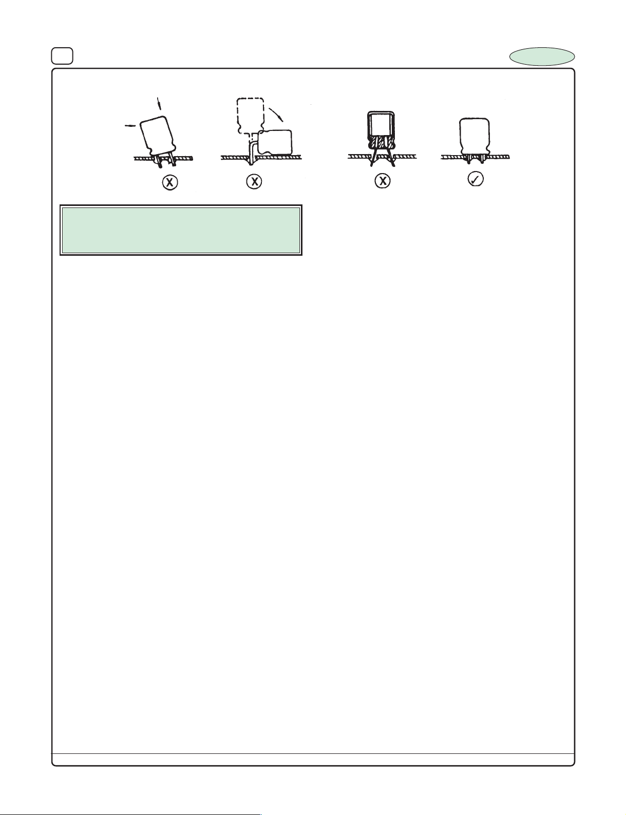
CAPACITOR POSITIONING METHOD
CAUTION :
Provide protection circuits and protection
devices to allow safe failure modes.
2. Capacitor Handling Techniques
2.1 Considerations Before Using
a) Capacitors have a finite life. Do not reuse or recycle capacitors
from used equipment.
b) Transient recovery voltage may be generated in the capacitor due
to dielectric absorption. If required, this voltage can be discharged
with a resistor of 1 KΩ.
c) Capacitors stored for long periods of time may exhibit an increase
in leakage current. This can be corrected by gradually applying
rated voltage in series through a 1KΩ resister.
d) If large capacitors are dropped, they can be damaged
machanically or electrically. Avoid using dropped capacitors.
e) Dented or crushed capacitors should not be used. This shall result
in short circuit / reduced life.
2.2 Capacitor Inser tion
a) Verify the correct capacitance and rated voltage of the capacitor.
b) Verify the correct polarity of the capacitor before inserting.
c) Verify the correct hole spacing before insertion to avoid stress on
the terminals.
d) Please ensure that while components are auto inserted, handling
and lead triming are carried out without developing stress at the
point where the lead is entering the seal (rubber bung) of the
capacitor.
2.3 Manual Soldering
a) Please ensure solder ing time is less than 3 sec. and temperature
not exceeding 350
b) If the capacitor leads are having a pitch different to that of PCB
the leads are to be formed to match the PCB, pitch in such a way
that no stress is developed on the capacitor.
c) If a soldered capacitor is to be removed and reinserted, avoid
excessive stress coming to the capacitor leads.
2.4 Soldering Considerations
a) Obser ve proper soldering conditions (temperature, time, etc.) Do
not exceed the specified limits.
b) Rapid temperature r ises during the preheat operation and resin
bonding operation can cause cracking of the capacitor vinyl sleeve.
For temperature curing, do not exceed 150
of 2 minutes.
2.5 Capacitor Handling after Soldering
a) Avoid bending of the capacitor after soldering to prevent excessive
stress on the leadwires where they enter the seal.
b) Do not use the capacitor as a handle when moving the circuit
board assembly.
c) Avoid striking the capacitor after assembly to prevent failure due
to exceessive Stress
2.6 Circuit Board Cleaning
a) Circuit boards can be immersed or ultrasonically cleaned using
suitable cleaning solvents for up to 5 minutes and up to 60
maximum temperatures. The boards should be thoroughly r insed
and dried.
0
C
0
c for a maximum time
0
Design, specifications are subject to change without notice.
b) Avoid using the following solvent groups.
Halogenated cleaning solvents : Halogenated Solvents can
permeate the seal and cause internal capacitor corrosion and
failure 1-1-1 trichloro ethane should never be used on Aluminium
Electrolytic Capacitor.
Alkali solvents : could attack and dissolve the aluminium case.
Petroleum based solvents : shall result deterioration of the rubber
seal.
Xylene : Deterioration of the rubber seal could result.
Acetone : Removal of the ink markings on the vinyl sleeve could
result. It will spoil the sleeve also.
c) A thorough drying after cleaning is required to remove residual
cleaning solvents which may be trapped between the capacitor
and the circuit board. Avoid dr ying temperature which exceed the
maximum rated temperature of the capacitor.
d) Monitor the contamination levels of the cleaning solvents during
use by electrical conductivity, pH, specific gra vity, or water content.
Chlorine levels can rise with contamination and adversely affect
the performance of the capacitor.
3. Precautions for using capacitors
3.1 Environmental Conditions
Capacitors should not be stored or used in the following
environments.
a) Temperature exposure above the maximum rated or below the
minimum rated temperature of the capacitor.
b) Direct contact with water, salt water, or oil.
c) High humidity conditions where water could condense on the
capacitor.
d) Exposure to toxic gases such as hydrogen sulphide, sulphuric
acid, nitric acid, chlorine, or ammonia.
e) Exposure to ozone radiation, or ultraviolet rays.
f) Vibration and shock conditions exceeding specified limit.
3.2 Electrical Precautions
a) Avoid touching the terminals of the capacitor to avoid electric
shock. The exposed aluminium case is not insulated and could
also cause electric shock if touched.
b) Avoid short circuiting of the capacitor terminals with conductive
materials including liquids such as acids or alkaline solutions.
4. Long Term Storage
Leakage current of a capacitor increases with long time storage.
The aluminium oxide film deteriorate as a function of temperature
and time. If used without conditioning, an abnormally high current
will be required to restore the oxide film. This current surge could
cause the circuit or the capacitor to fail. Capacitor should be
conditioned by applying rated voltage in series with a 1KΩ, current
limiting resistor for a period of min. 30 minutes.
NOTES :
C
INCAP
Page 9
7 ALUMINIUM ELECTROLYTIC CAPACITORS
INCAP
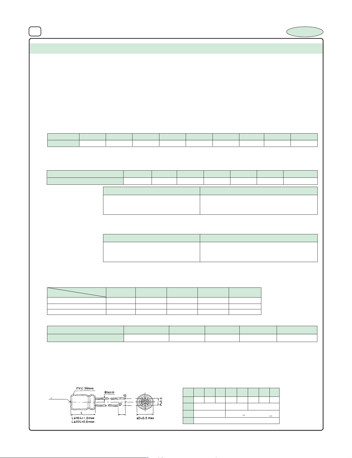
SERIES : IG
TYPE : Radial - Low Voltage
FEATURES : 850C, 2000 hours category
SPECIFICATION TABLE :
1. OPERATING TEMPERATURE RANGE : – 40
2. VOLTAGE RANGE : 6.3V - 100 VDC
3. CAPACITANCE RANGE : 0.1µF to 22,000 µF
4. CAPACITANCE TOLERANCE at 25
5. LEAKAGE CURRENT at 25
6. DISSIPATION FACTOR (Tan δ) at 250C, 120 Hz :
Voltage
DF
Note : For capacitors whose cap value exceeds 1000 µF, specification of "Tan δ" is increased by 0.02 for every addition of
1000 µF and part of it.
7. TEMPERATURE CHARACTERISTICS (impedance ratio at 120 Hz) :
Rated Voltage
Z(-400C) / Z (+200C)
8. LOAD LIFE TEST :
The Capacitor after load life test for 2000 hrs. at 85
Note : A recovery time of 16 hrs. should be given before taking the measurments after load life test.
9. SHELF TEST :
The Capacitor after shelf test for 1000 hrs. at 85
Note : A recovery time of 16 hrs. should be given before taking the measurments after Shelf test.
10. RIPPLE CURRENT & FREQUENCY MULTIPLIERS :
Cap. (µF)
Below 100 0.70 1.00 1.30 1.40 1.50
100 to 1000 0.75 1.00 1.20 1.30 1.35
1000 and above 0.80 1.00 1.10 1.12 1.15
11. RIPPLE CURRENT & TEMPERATURE MULTIPLIERS :
6.3
0.22 0.22 0.20 0.16 0.16 0.16 0.14 0.12 0.10
Freq. (Hz)
Temperature (0C)
Multiplier
0
C, 120 Hz : +_ 20%
0
C (after 3min. Charging) : 0.01 CV or 3 µA which ever is greater
10 16 25 35 40 50 63 100
6.3
12 10 8 6 4 4 3
Test Time 2000 Hrs
Capacitance Change +_ 20% of the initial masured Value
Dissipation Factor Less than 200% of Specified Value
Leakage Current Within specified Value
0
C should meet the above specification
Test Time
Capacitance Change +_ 20% of the initial mesured value
Dissipation Factor Less than 200% of Specified Value
Leakage Current Within specified Value
0
C should meet the above specification
Below 40
1.3 1.15 1.00
General Purpose Low Voltage
0
C to 850 C
10 16 25
1K50012060 (50)
50
1.28
60
1.25
(C=Capacitance Value, V=Rated Voltage)
35 40 50 to 100
1000 Hrs
≥≥
≥ 10K
≥≥
70 85
12. MARKING :
Brand Name, Capacitance Value, Working Voltage, Polarity Marking, Operating Temperature, Month of Manufacture & 'Vent' from
8mm and above.
13. STANDARDS : As per IEC 384-4.
14. DIMENSIONS (NOT TO SCALE) :
LEAD SPACING AND DIAMETER
5 6.3 8 10 13 16 18 22
(>8mm dia)
Vent
5mm
Min
φD
P 2.0 2.5 3.5 5.0 5.0 7.5 7.5 10
φ
d 0.5 0.6 0.8
α
β 0.5
1.0 1.0 for L
<
16, 2.0 for L
> 20
Page 10
8 ALUMINIUM ELECTROLYTIC CAPACITORS
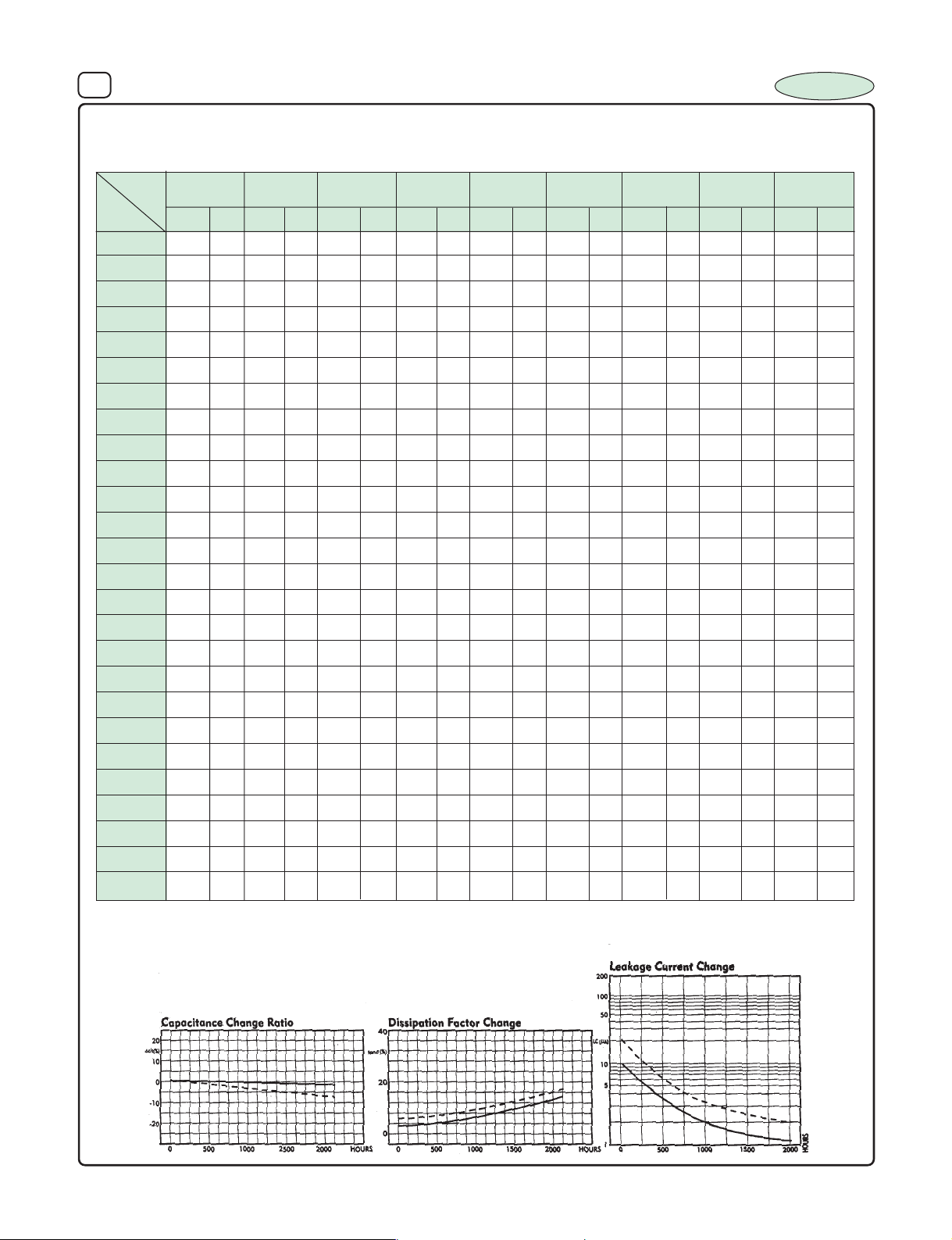
15. DIMENSIONS Vs PERMISSIBLE RIPPLE CURRENT :
Dimensions : D x L (mm), Ripple Current (I
) : mA/rms at 120 Hz 850C
A
INCAP
W.V .
µF
0.1
0.22
0.33
0.47
1
2.2
3.3
4.7
10
22
33
47
100
150
220
330
470
1000
1500
2200
3300
4700
6800
10000
15000 22x43 4000
22000 22x43 4100
6.3
I
DxL
5x11 130 5x11 146 6.3x11 170 6.3x11 204 8x11 215 8x11 220 8x11 275 10x13 297 13x21 400
6.3x11
8x11 283 8x11 303 8x11 370 10x16 400 10x16 510 10x20 550 10x20 600 13x21 675 16x32 900
8x11 340 8x11 500 10x13 505 10x16 601 10x26 630 10x20 675 13x21 760 13x21 920 16x36 1050
10x13 550 10x16 650 10x16 800 13x21 1000 13x21 1145 16x25 1200 16x25 1350 16x32 1510 18x43 1950
10x20 985 13x21 1100 13x21 1330 16x25 1575 16x32 1900 16x32 1925 18x32 2000 22x37 2100
13x21 1245 13x21 1460 16x25 1720 16x32 1900 18x37 2190 . 22x37 2500
16x25 1675 16x25 1800 16x32 2000 18x37 2200 18x43 2500 . 22x43 3300 .
. 16x36 2050 . ...
16x32 2375 22x37 2500 22x37 3000 22x43 3420
10
I
DxL
A
205 6.3x11 220 8x11 302 8x11 330 10x13 381 10x16 400 10x16 434 10x20 485 16x25 710
16
DxL
A
5x11 40 5x11 50 5x11 54 5x11 57 5x11 62 5x11 65 6.3x11 85
. 5x11 70 5x11 78 5x11 90 5x11 95 5x11 100 6.3x11 112 8x11 120
. 5x11 100 5x11 101 6.3x11 103 6.3x11 106 6.3x11 120 8x11 143 10x13 170
5x11 115 5x11 121 6.3x11 140 6.3x11 150 6.3x11 160 8x11 204 10x13 220
6.3x11 210 8x11 240.
25
I
DxL
I
A
35
DxL
A
I
40
DxL
A
. 18x32 1500 18x37 1750
I
50
DxL
A
I
5x11 2.0 5x11 3 5x11 3
5x11 3.5 5x11 4.5 5x11 5
5x11 5 5x11 7.5 5x11 8
5x11 9 5x11 14 5x11 16
5x11 19 5x11 20 5x11 23
5x11 30 5x11 32 5x11 34
5x11 35 5x11 37 5x11 42
5x11 45 5x11 52 6.3x11 54
63
DxL
A
100
DxL
I
A
I
A
16. LIFE TEST A T RA TED VOL T A GE AND TEMPERATURE :
________ 47 µF 25 WV
................ 100
µF 25 WV
Page 11
9 ALUMINIUM ELECTROLYTIC CAPACITORS
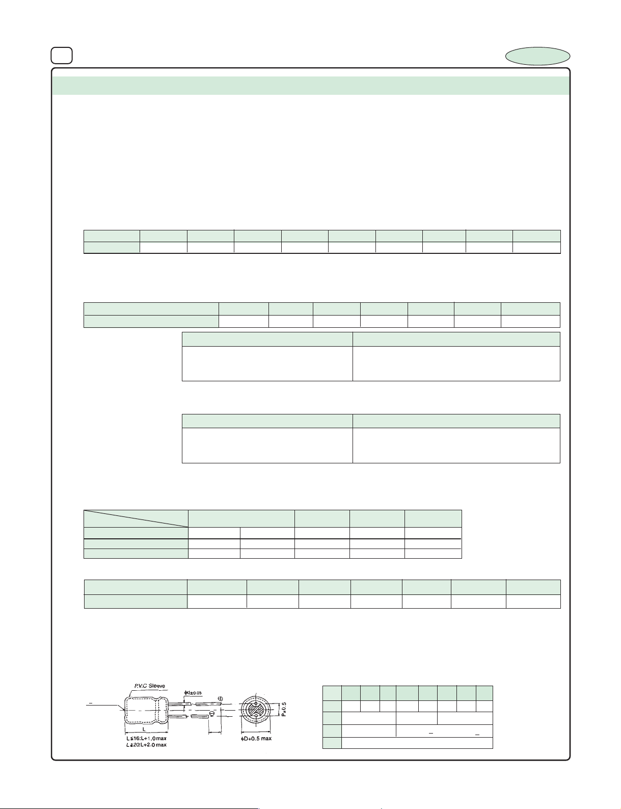
SERIES : IT
INCAP
TYPE : Radial - Low Voltage
FEATURES : 105
SPECIFICATION TABLE :
1. OPERATING TEMPERATURE RANGE : – 40
2. VOLTAGE RANGE : 6.3V - 100 VDC
3. CAPACITANCE RANGE : 0.1µF to 10000 µF
4. CAPACITANCE TOLERANCE at 25
5. LEAKAGE CURRENT at 25
6. DISSIPATION FACTOR (Tan δ) at 250C, 120 Hz :
Voltage
DF
Note : For capacitors whose cap value exceeds 1000 µF, specification of "Tan δ" is increased by 0.02 for every addition of
1000 µF and part of it.
7. TEMPERATURE CHARACTERISTICS (impedance ratio at 120 Hz) :
Rated Voltage
Z(-400C) / Z (+200C)
8. LOAD LIFE TEST :
The Capacitor after load life test for 2000 hrs. at 105
Note : A recovery time of 16 hrs. should be given before taking the measur ments after load life test.
6.3
0.22 0.22 0.20 0.16 0.16 0.16
0
C, 120 Hz : +_ 20%
0
C (after 3min. Charging) : 0.01 CV or 3 µA which ever is greater
10 16 25 35 40 50 63 100
6.3
12 10 8 6 4 4 3
Test Time 2000 Hrs
Capacitance Change +_ 20% of the initial masured Value
Dissipation Factor Less than 200% of Specified Value
Leakage Current Within specified Value
0
C should meet the above specification
0
C, 2000 hours category
General Purpose Low Voltage
0
C to 1050 C
10 16 25
(C=Capacitance Value, V=Rated Voltage)
0.14 0.12 0.10
35
40
50 to 100
9. SHELF TEST :
Capacitance Change +_ 20% of the initial mesured value
Dissipation Factor Less than 200% of Specified Value
Leakage Current Within specified Value
The Capacitor after shelf test for 1000 hrs. at 105
Note : A recovery time of 16 hrs. should be given before taking the measurments after shelf test.
10. RIPPLE CURRENT & FREQUENCY MULTIPLIERS :
Cap. (µF)
Below 100 0.70 1.00 1.30 1.40 1.50
100 to 1000 0.75 1.00 1.20 1.30 1.35
1000 and above 0.80 1.00 1.10 1.12 1.15
11. RIPPLE CURRENT & TEMPERATURE MULTIPLIERS :
Temperature (0C)
Multiplier
12. MARKING :
Brand Name, Capacitance Value, Working Voltage, Polarity Marking, Operating Temperature, Month of Manufacture & 'Vent' from
8mm and above.
13. DIMENSIONS (NOT TO SCALE) :
(>8mm dia)
Vent
Freq. (Hz)
Below 40
1.9 1.6 1.35
5mm
Min
Test Time
0
C should meet the above specification
50
1.8
60
1.7
LEAD SPACING AND DIAMETER
5 6.3 8 10 13 16 18 22
φD
P 2.0 2.5 3.5 5.0 5.0 7.5 7.5 10
φ
d 0.5 0.6 0.8
α
β 0.5
1.0
≥≥
≥ 10K
1K50012060 (50)
≥≥
70 85
1.0 for L
1000 Hrs
<
16, 2.0 for L
90
1.25
> 20
105
1.0
Page 12
10 ALUMINIUM ELECTROLYTIC CAPACITORS
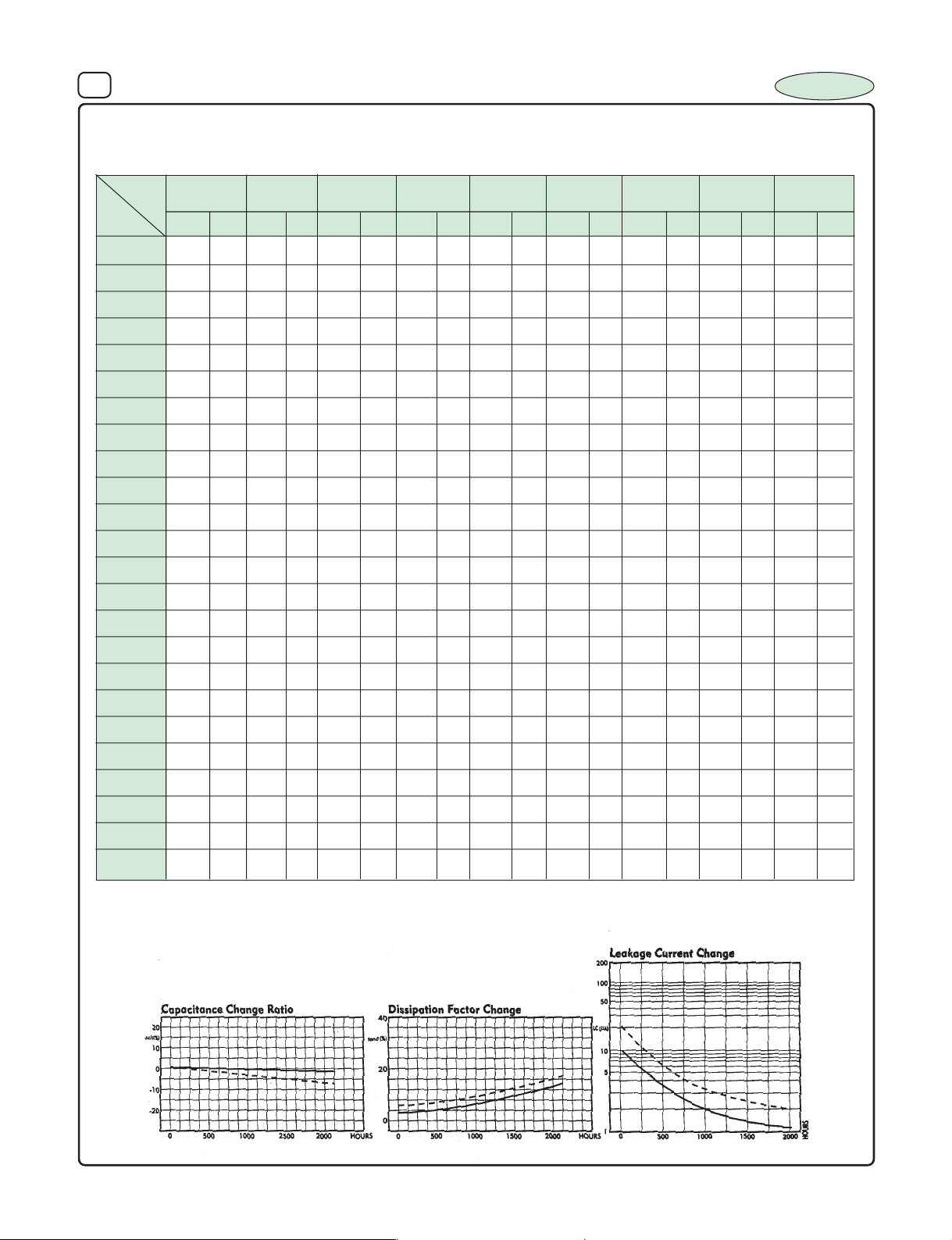
14. DIMENSIONS Vs PERMISSIBLE RIPPLE CURRENT :
Dimensions : D x L (mm), Ripple Current (IA): mA/rms at 120 Hz 1050C
INCAP
µF
W.V .
0.1
0.22
0.33
0.47
2.2
3.3
4.7
10
22
33
47
100
150
220
6.3
I
DxL
1
6.3x11
A
5x11 111 5x11 125 6.3x11 146 6.3x11 165 8x11 175 8x11 180 8x11 208 10x13 224 13x21 300
175 6.3x11 190 8x11 260 8x11 270 10x13 300 10x16 325 10x16 330 10x20 365 16x25 534
10
I
DxL
. 5x11 79 5x11 90 5x11 97 6.3x11 115 6.3x11 120 6.3x11 123 8x11 155 10x13 170
16
DxL
A
. 5x11 60 5x11 63 5x11 71 5x11 75 5x11 78 6.3x11 84 8x11 91
6.3x11 178 8x11 204.
I
5x11 35 5x11 41 5x11 44 5x11 47 5x11 48 5x11 50 6.3x11 65
5x11 70 5x11 75 6.3x11 82
25
I
DxL
A
35
I
DxL
A
A
40
DxL
6.3x11
50
I
DxL
A
87 6.3x11 91 8x11 108 10x13 130
I
5x11 1.2 5x11 2.3 5x11 2.4
5x11 2.1 5x11 3.4 5x11 3.75
5x11 3.8 5x11 5.7 5x11 6.2
5x11 7 5x11 10.5 5x11 12.5
5x11 15 5x11 15 5x11 18
5x11 23 5x11 25 5x11 26
5x11 27 5x11 28 5x11 32
5x11 35 5x11 39 6.3x11 42
63
I
DxL
A
A
DxL
100
I
A
330
470
1000
1500
2200
3300
4700
6800
10000
8x11 245 8x11 260 8x11 316 10x16 322 10x16 405 10x20 450 10x20 460 13x21 507 16x32 676
8x11 290 8x11 430 10x13 431 10x16 500 10x26 504 10x20 540 13x21 570 13x21 700 16x36 790
10x13 460 10x16 560 10x16 685 13x21 804 13x21 916 16x25 970 16x25 1015 16x32 1150 18x43 1500
10x20 740 13x21 900 13x21 1030 . 18x32 1250 18x37 1350
10x20 840 13x21 935 13x21 1132 16x25 1260 16x32 1530 16x32 1540 18x32 1550 22x37 1600
13x21 1060 13x21 1250 16x25 1475 16x32 1530 18x37 1670 . 22x37 1750
16x25 1450 16x25 1500 16x32 1700 18x37 1775 18x43 2000 . 22x43 2500 .
. 16x36 1710 . ...
16x32 2020 22x37 2125 22x37 2600 22x43 3200.
15. LIFE TEST A T RA TED VOL T A GE AND TEMPERATURE :
________ 47 µF 25 WV
................ 100
µF 25 WV
Page 13
11 ALUMINIUM ELECTROLYTIC CAPACITORS
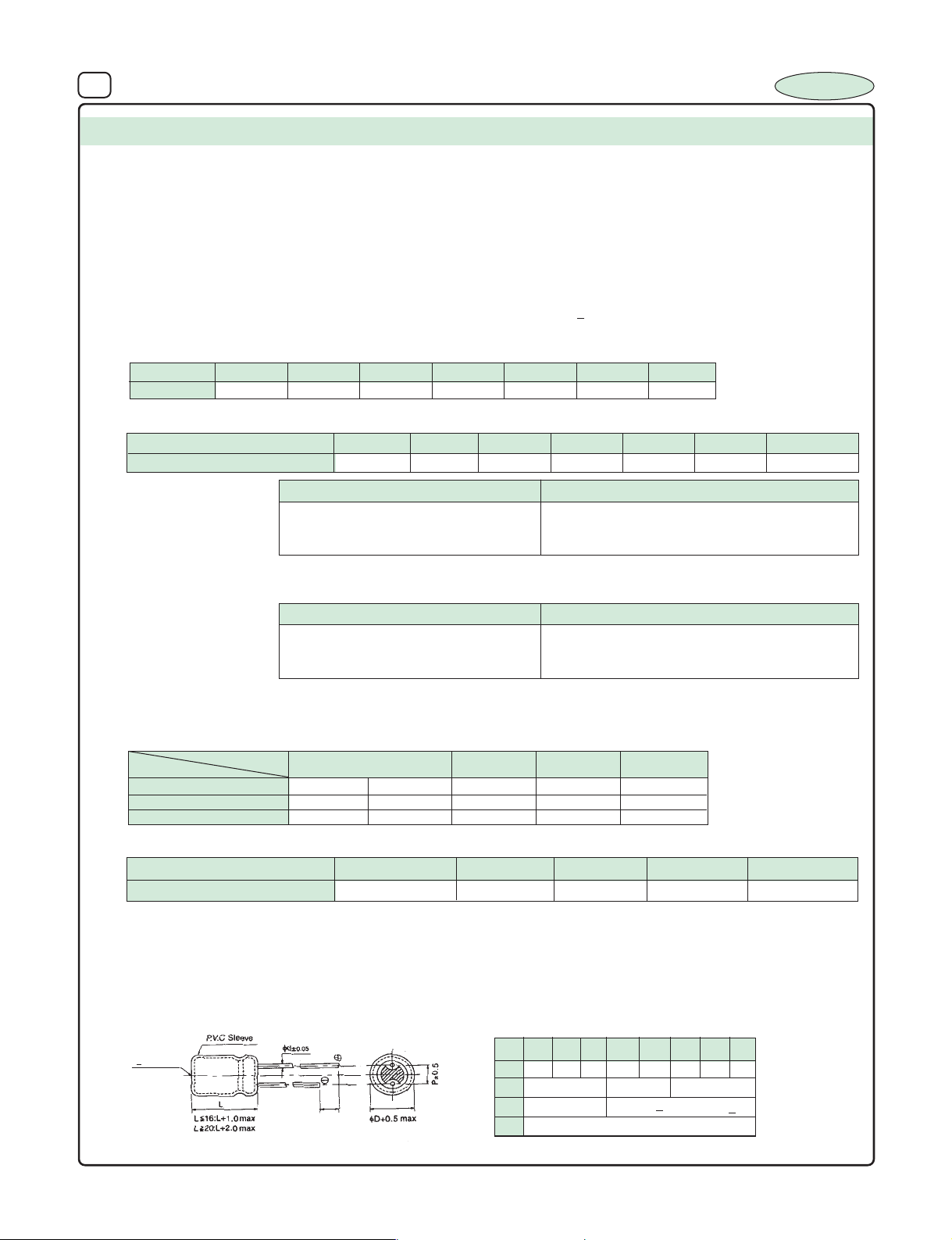
SERIES : IH 1
TYPE : Radial Medium & High Voltage
FEATURES : 850C, 2000 hours assured
SPECIFICATION TABLE :
1. OPERATING TEMPERATURE RANGE : – 40
2. VOLTAGE RANGE : 160V - 450 VDC
3. CAPACITANCE RANGE : 0.47µF to 330 µF
4. CAPACITANCE TOLERANCE at 25
5. LEAKAGE CURRENT at 25
6. DISSIPATION FACTOR (Tan δ) at 250C, 120 Hz :
Voltage
DF
7. TEMPERATURE CHARACTERSTICS (impedance ratio at 120 Hz) :
Rated Voltage
Z(-400C) / Z (+200C)
160
0.12 0.14 0.17 0.20 0.25 0.25
0
C, 120 Hz : +_ 20%
0
C (after 3min. Charging) : 0.03 CV + 15 µA (CV<1000)
200 250 350 400 420 450
160
444688 8
Standard Series for General Purpose Medium & High Voltage
0
C to 850C
0.02 CV + 25 µA (CV> 1000)
200 250 350
INCAP
(C=Capacitance Value, V=Rated Voltage)
0.25
400
420
450
8. LOAD LIFE TEST :
Capacitance Change +_ 20% of the initial masured Value
Dissipation Factor Less than 200% of Specified Value
Leakage Current Within specified Value
The Capacitor after load life test for 2000 hrs. at 850C should meet the above specification
Note : A recovery time of 16 hrs. should be given before taking the measur ments after load life test.
9. SHELF TEST :
Capacitance Change +_ 20% of the initial mesured value
Dissipation Factor Less than 200% of Specified Value
Leakage Current Within specified Value
The Capacitor after shelf test for 1000 hrs. at 85
Note : A recovery time of 16 hrs. should be given before taking the measur ments after shelf test.
10. RIPPLE CURRENT & FREQUENCY MULTIPLIERS :
Cap. (µF)
Below 100 0.70 1.00 1.30 1.40 1.50
100 to 1000 0.75 1.00 1.20 1.30 1.35
1000 and above 0.80 1.00 1.10 1.12 1.15
11. RIPPLE CURRENT & TEMPERATURE MULTIPLIERS :
Freq. (Hz)
Temperature (0C)
Multiplier
12. MARKING :
Brand Name, Capacitance Value, Working Voltage, Polarity Marking, Operating Temperature, Month of Manufacture & Vent from
8mm and above.
13. DIMENSIONS (NOT TO SCALE) :
Test Time 2000 Hrs
Test Time
0
C should meet the above specification
1K50012060 (50)
Below 40
1.3 1.15 1.00
50
1.28
60
1.25
1000 Hrs
≥≥
≥ 10K
≥≥
70 85
(>8mm dia)
Vent
5mm
Min
LEAD SPACING AND DIAMETER
5 6.3 8 13 16 18 22
φD
P 2.0 2.5 3.5 5.0 5.0 7.5 7.5 10
φ
d 0.5 0.6 0.8
α
β 0.5
1.0 1.0 for L
<
16, 2.0 for L
> 20
Page 14
12 ALUMINIUM ELECTROLYTIC CAPACITORS
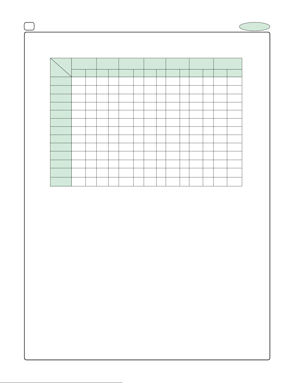
14. DIMENSIONS Vs PERMISSIBLE RIPPLE CURRENT :
Dimensions : D x L (mm), Ripple Current (IA): mA/rms at 120 Hz 850C
INCAP
W.V .
µF
0.47 6.3x11 12
1.0 5x11 17 6.3x11 18 6.3x11 18 6.3x11 22 8x11 25 8x11 25 8x11 26
2.2 6.3x11 28 8x11 30 8x11 31 8x11 35 10x13 36 10x13 36 10x13 38
3.3 8x11 38 8x11 40 8x11 42 10x13 43 10x16 45 10x20 48 10x20 50
4.7 8x11 45 8x11 48 10x13 50 10x20 51 10x20 52 10x20 60 10x20 65
10 10x16 75 10x16 78 10x16 85 13x21 93 16x25 95 16x25 100 16x25 110
22 10x16 125 10x20 120 13x21 130 16x25 135 16x25 148 16x32 155 16x32 160
33 10x20 170 13x21 185 16x25 200 16x32 210 16x32 225 16x36 240 16x36 250
47 13x21 200 16x25 210 16x25 215 16x36 240 16x36 260 18x37 265 18x37 270
100 16x25 350 16x32 375 16x32 390 18x37 450
150 16x36 450 18x32 460
220 18x37 550 18x37 575
330 22x37 675
DxL
160
200
I
DxL
A
250
I
DxL
A
350
I
DxL
A
400
I
DxL
A
420
I
DxL
A
I
A
DxL
450
I
A
Note :
We Recommand to use only IL1 / IL2 / IL5 series of Capacitors for
CFL / BALLAST / INVERTOR / CONVERTOR and OTHER HIGH RELIABLE
APPLICATIONS.
Large radial capacitors of 22 φ and 25 φ can be supplied to meet
specific requirement.
Page 15
13 ALUMINIUM ELECTROLYTIC CAPACITORS
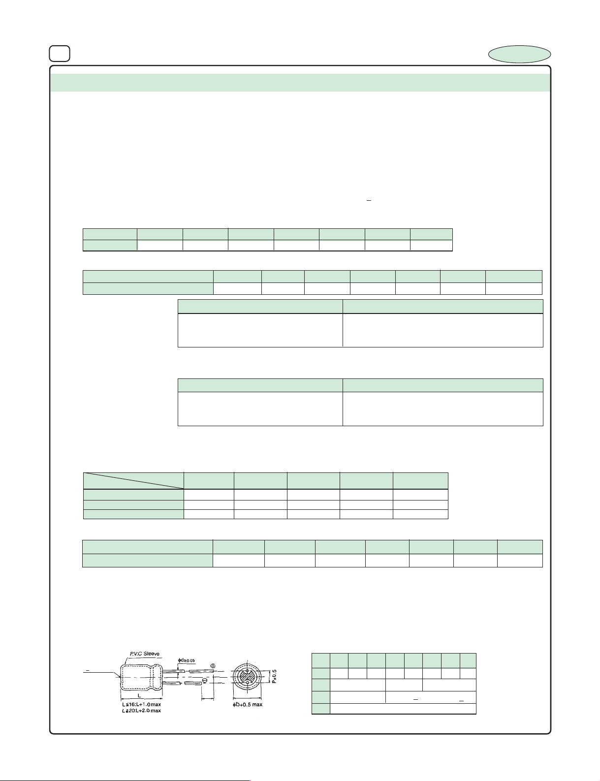
SERIES : IH 2
TYPE : Radial Medium & High Voltage
FEATURES : 1050C, 2000 hours assured
SPECIFICATION TABLE :
1. OPERATING TEMPERATURE RANGE : – 40
2. VOLTAGE RANGE : 160V - 450 VDC
3. CAPACITANCE RANGE : 0.47µF to 220 µF
4. CAPACITANCE TOLERANCE at 25
5. LEAKAGE CURRENT at 25
6. DISSIPATION FACTOR (Tan δ) at 250C, 120 Hz :
Voltage
DF
7. TEMPERATURE CHARACTERSTICS (impedance ratio at 120 Hz) :
Rated Voltage
Z(-400C) / Z (+200C)
160
0.12 0.14 0.17 0.20 0.25 0.25
0
0
C, 120 Hz : +_ 20%
C (after 3min. Charging) : 0.03 CV + 15 µA (CV<1000)
200 250 350 400 420 450
160
444688 8
Standard Series for General Purpose Medium & High Voltage
0
C to 1050C
0.02 CV + 25 µA (CV> 1000)
200 250 350
INCAP
(C=Capacitance Value, V=Rated Voltage)
0.25
400
420
450
8. LOAD LIFE TEST : :
Capacitance Change +_ 20% of the initial masured Value
Dissipation Factor Less than 200% of Specified Value
Leakage Current Within specified Value
The Capacitor after load life test for 2000 hrs. at 105
Note : A recovery time of 16 hrs. should be given before taking the measurments after load life test.
9. SHELF TEST :
Capacitance Change +_ 20% of the initial mesured value
Dissipation Factor Less than 200% of Specified Value
Leakage Current Within specified Value
The Capacitor after shelf test for 1000 hrs. at 105
Note : A recovery time of 16 hrs. should be given before taking the measur ments after shelf test.
10. RIPPLE CURRENT & FREQUENCY MULTIPLIERS :
Cap. (µF)
Below 100 0.70 1.00 1.30 1.40 1.50
100 to 1000 0.75 1.00 1.20 1.30 1.35
1000 and above 0.80 1.00 1.10 1.12 1.15
11. RIPPLE CURRENT & TEMPERATURE MULTIPLIERS :
Freq. (Hz)
Temperature (0C)
Multiplier
12. MARKING :
Brand Name, Capacitance Value, Working Voltage, Polarity Marking, Operating Temperature Month of Manufacture & Vent from
8mm and above.
Test Time 2000 Hrs
0
C should meet the above specification
Test Time
0
C should meet the above specification
1K50012060 (50)
Below 40
1.9
50
1.8
60
1.7
70
1.6
1000 Hrs
≥≥
≥ 10K
≥≥
1.35
85
90
1.25
105
1.00
13. DIMENSIONS (NOT TO SCALE) :
(>8mm dia)
Vent
5mm
Min
LEAD SPACING AND DIAMETER
5 6.3 8 10 13 16 18 22
φD
P 2.0 2.5 3.5 5.0 5.0 7.5 7.5 10
φ
d 0.5 0.6 0.8
<
α
β 0.5
1.0 1.0 for L
16, 2.0 for L
> 20
Page 16
14 ALUMINIUM ELECTROLYTIC CAPACITORS
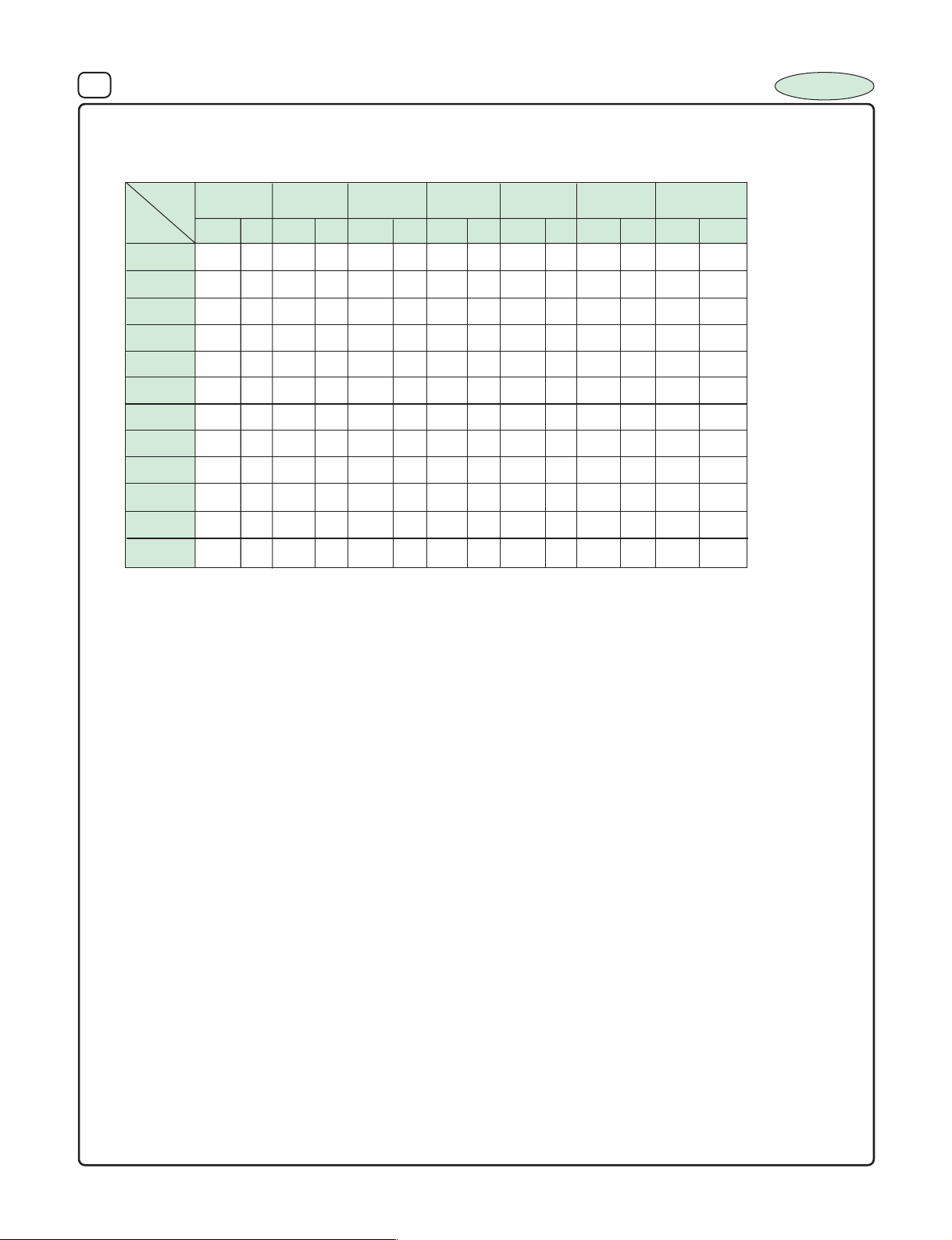
14. DIMENSIONS Vs PERMISSIBLE RIPPLE CURRENT :
Dimensions : D x L (mm) Ripple Current (IA) : mA/rms at 120 Hz 1050C
INCAP
mF
Note :
W.V .
0.47 6.3x11 11 6.3x11 11.1 8x11 11.2 8x11 11.5 8X11 12
1.0 5x11
2.2 6.3x11 22 8x11 23 8x11 24.2 8x11 24.5 10x13 29 10x13 30 10x13 31
3.3 8x11 32 8x11 33 8x11 35 10x13 33 10x16 40 10x16 42 10x16 48
4.7 8x11 35 8x11 41 10x13 40 10x20 42 10x20 45 10x20 56 10x20 60
10 10x16 55 10x16 65 10x20 72 13x21 80 16x25 87 16x25 100 16x25 100
22 10x20 95 10x20 112 13x21 125 13x21 130 16x25 145 16x32 148 16x32 150
33 13x21 140 13x21 160 16x25 165 16x32 170 16x32 185 16x36 190 16x36 200
47 13x21 160 16x25 190 16x32 205 16x36 212 16x36 220 18x37 230 18x37 250
100 16x32 280 16x32 300 16x36 320 18x37 335
150 16x36 365
220 18x37 435
DxL
160
200
DxL I
I
A
13.8 6.3x11
250
DxL
A
14.2 6.3x11 15.8 8x11 17 8x11 17.5 8x11 17.8 10x13 18.5
350
I
DxL
A
400
I
DxL
A
420
I
DxL
A
I
A
DxL
450
I
A
We Recommand to use only IL1 / IL2 / IL5 series of Capacitors for
CFL / BALLAST / INVERTOR / CONVERTOR and OTHER HIGH RELIABLE
APPLICATIONS.
Large radial capacitors of 22 φ and 25 φ can be supplied to meet
specific requirement.
Page 17
15 ALUMINIUM ELECTROLYTIC CAPACITORS
SERIES : BP 1
TYPE : Radial - Bi-polar
FEATURES : 850C, 2000 hours Catagory
SPECIFICATION TABLE :
1. OPERATING TEMPERATURE RANGE : – 40
2. VOLTAGE RANGE : 25 - 100 VDC
3. CAPACITANCE RANGE : 1.5µF to 10µF
4. CAPACITANCE TOLERANCE at 25
5. LEAKAGE CURRENT at 25
6. DISSIPATION FACTOR (Tan δ) at 250C, 120 Hz :
Voltage
DF
7. LOAD LIFE TEST :
25
0.05
0
C, 120 Hz : + 20%
0
C : 0.2 CV (C=Capacitance V alue, V=Rated Voltage)
63
0.08
100
0.10
Test Time 2000 Hrs
Capacitance Change +_ 20% of the initial masured Value
Dissipation Factor Less than 200% of Specified Value
Leakage Current Within specified Value
Designed Specially for cross over network in high frequency
sound systems, Horizontal Deflection Correction in B&W TV.
Suitable for improving Audio Tone and speaker networks
0
C to 850C
INCAP
The Capacitor after load life test for 2000 hrs. at 850C should meet the above specification. Voltage connection to be reversed after every 250 hrs of test.
Note : A recovery time of 16 hrs. should be given before taking the measur ments after load life test.
8. SHELF TEST :
Test Time
Capacitance Change +_ 20% of the initial mesured value
Dissipation Factor Less than 200% of Specified Value
Leakage Current Within specified Value
The Capacitor after shelf test for 1000 hrs. at 85
Note : A recovery time of 16 hrs. should be given before taking the measur ments after load life test.
9. RIPPLE CURRENT & FREQUENCY MULTIPLIERS :
Cap. (µF)
Below 100 0.70 1.00 1.30 1.40 1.50
100 to 1000 0.75 1.00 1.20 1.30 1.35
1000 and above 0.80 1.00 1.10 1.12 1.15
10. MARKING :
Brand Name, Capacitance Value, Working Voltage, Operating Temperature, Month of Manufacture & 'Vent' from 8 and above.
11. DIAGRAM DIMENSIONS :
(>8mm dia)
Vent
Freq. (Hz)
5mm
Min
0
C should meet the above specification.
1000 Hrs
1K50012060 (50)
LEAD SPACING AND DIAMETER
5 6.3 8 10 13 16 18 22
φD
P 2.0 2.5 3.5 5.0 5.0 7.5 7.5 10
φ
d 0.5 0.6 0.8
α
β 0.5
1.0 1.0 for L
≥≥
≥
≥≥
10K
<
16, 2.0 for L
> 20
Page 18
16 ALUMINIUM ELECTROLYTIC CAPACITORS
12. DIMENSIONS Vs PERMISSIBLE RIPPLE CURRENT :
Dimensions : D x L (mm) Ripple Current (IA) : A/rms at 120 Hz 850C
INCAP
W.V .
µF DxL
1.5 8x11 2.0 10x13 10x13
2.2 10x13 3.0 10x13 10x20
3.3 13x21 4.0 10x13 10x20
4.7 16x25 7.0 10x16 10x20
6.8 16x32 8.0 10x20 13x21
8.2 16x36 8.1 10x20 13x21
10 16x36 8.2 10x20 13x21
For 63 wv and 100 wv capacitors, ripple current is as per the requirment of customer.
25
I
For use in
Horizontal
deflection
correction
Circuits in T.V.
63
A
DxL
For use in
Hi-Fi Network
Circuits.
100
DxL
Page 19
17 ALUMINIUM ELECTROLYTIC CAPACITORS
SERIES : NP 1
TYPE : Radial - Non-polar
0
FEATURES : 85
SPECIFICATION TABLE :
1. OPERATING TEMPERATURE RANGE : – 40
2. VOLTAGE RANGE : 6.3 - 100 V DC
3. CAPACITANCE RANGE : 0.47 µF to 2200 µF
4. CAPACITANCE TOLERANCE at 25
5. LEAKAGE CURRENT at 250C : 0.03 CV (C=Capacitance V alue, V=Rated Voltage)
6. DISSIPATION FACTOR (Tan δ) at 250C, 120 Hz :
0
C, 120 Hz : + 20%
C, 2000 hours Catagory, General pur pose
Non-polar Capacitors which can be used in either Polarity and are
Suitable for indeterminate polarity circuits.
0
C to 850C
INCAP
Voltage
DF
7. LOAD LIFE TEST :
6.3
30
10
30
16
25
25
25
35
25
50
16
63
16
100
16
Test Time 2000 Hrs
Capacitance Change +_ 20% of the initial masured Value
Dissipation Factor Less than 200% of Specified Value
Leakage Current Within specified Value
The Capacitor after load life test for 2000 hrs. at 850C should meet the above specification. Voltage connection to be reversed after every 250 hrs of test.
Note : A recovery time of 16 hrs. should be given before taking the measur ments after load life test.
8. SHELF TEST :
Test Time
Capacitance Change +_ 20% of the initial mesured value
Dissipation Factor Less than 200% of Specified Value
Leakage Current Within specified Value
The Capacitor after shelf test for 1000 hrs. at 85
Note : A recovery time of 16 hrs. should be given before taking the measur ments after load life test.
9. MARKING :
Brand Name, Capacitance Value, Working Voltage, Operating Temperature, Month of Manufacture & 'Vent' from 8 and above.
10. DIAGRAM DIMENSIONS :
0
C should meet the above specification.
1000 Hrs
(>8mm dia)
Vent
5mm
Min
LEAD SPACING AND DIAMETER
5 6.3 8 10 13 16 18 22
φD
P 2.0 2.5 3.5 5.0 5.0 7.5 7.5 10
φ
d 0.5 0.6 0.8
α
β 0.5
1.0 1.0 for L
<
16, 2.0 for L
> 20
Page 20
18 ALUMINIUM ELECTROLYTIC CAPACITORS
11. DIMENSIONS Vs PERMISSIBLE RIPPLE CURRENT :
Dimensions : D x L (mm) Ripple Current (IA) : mA/rms at 120 Hz 850C
INCAP
W.V .
µ F
0.47 5x11 7 5x11 8
1.0 5x11 10 5x11 12
2.2 5x11 15 6.3x11 20
3.3 5x11 19 5x11 23 8x11 27
4.7 5x11 21 6.3x11 27 6.3x11 28 8x11 33
10 5x11 28 5x11 34 6.3x11 36 6.3x11 43 8x11 44 10x16 64
22 6.3x11 48 6.3x11 58 8x11 60 8x11 76 10x13 88 13x21 121
33 5x11 35 8x11 59 8x11 84 8x11 86 10x13 104 10x13 118 13x21 148
47 5x11 50 6.3x11 63 8x11 83 8x11 110 10x13 113 10x13 136 10x16 164 13x25 191
100 6.3x11 80 8x11 108 8x11 133 10x13 178 10x16 211 10x20 233 13x21 296 16x25 351
6.3
DxL I
10
DxL
A
16
DxL
A
I
25
DxL
A
I
A
DxL
35
DxL
63
100
DxLI
I
A
50
DxL
I
A
I
A
I
A
220 8x11 142 10x13 196 10x13 259 10x16 338 10x25 389 13x25 424 16x25 482
330 10x13 193 10x13 284 10x16 342 10x20 476 13x25 476 16x25 610
470 10x16 254 10x16 339 10x20 470 13x25 615 16x25 624
1000 13x25 464
2200 16x25 868
Page 21
19 ALUMINIUM ELECTROLYTIC CAPACITORS
SERIES : NP 2
TYPE : Radial - Non-polar
0
FEATURES : 105
SPECIFICATION TABLE :
1. OPERATING TEMPERATURE RANGE : – 400C to 1050C
2. VOLTAGE RANGE : 6.3 - 100 V DC
3. CAPACITANCE RANGE : 0.47 µF to 2200 µF
4. CAPACITANCE TOLERANCE at 25
5. LEAKAGE CURRENT at 25
6. DISSIPATION FACTOR (Tan δ) at 250C, 120 Hz :
0
C, 120 Hz : + 20%
0
C : 0.03 CV (C=Capacitance V alue, V=Rated Voltage)
C, 1000 hours Catagory
Non-polar Capacitors which can be used in either Polarity and are
Suitable for indeterminate polarity circuits.
INCAP
Voltage
DF
7. LOAD LIFE TEST :
25
25
63
16
100
16
Test Time 1000 Hrs
Capacitance Change +_ 20% of the initial masured Value
Dissipation Factor Less than 200% of Specified Value
Leakage Current Within specified Value
The Capacitor after load life test for 1000 hrs. at 850C should meet the above specification. Voltage connection to be reversed after every 250 hrs of test.
Note : A recovery time of 16 hrs. should be given before taking the measur ments after load life test.
8. SHELF TEST :
Test Time
Capacitance Change +_ 20% of the initial mesured value
Dissipation Factor Less than 200% of Specified Value
Leakage Current Within specified Value
0
The Capacitor after shelf test for 5000 hrs. at 85
Note : A recovery time of 16 hrs. should be given before taking the measur ments after load life test.
9. MARKING :
Brand Name, Capacitance Value, Working Voltage, Operating Temperature, Month of Manufacture & 'Vent' from 8 and above.
C should meet the above specification.
500 Hrs
10. DIAGRAM DIMENSIONS :
(>8mm dia)
Vent
5mm
Min
LEAD SPACING AND DIAMETER
5 6.3 8 10 13 16 18 22
φD
P 2.0 2.5 3.5 5.0 5.0 7.5 7.5 10
φ
d 0.5 0.6 0.8
<
α
β 0.5
1.0 1.0 for L
16, 2.0 for L
> 20
Page 22
20 ALUMINIUM ELECTROLYTIC CAPACITORS
11. DIMENSIONS Vs PERMISSIBLE RIPPLE CURRENT :
Dimensions : D x L (mm) Ripple Current (IA) : mA/rms at 120 Hz 850C
INCAP
W.V .
µ F
0.47 5x11 7.4 5x11 8.5
1.0 5x11 10.5 5x11 12.7
2.2 5x11 15.7 6.3x11 21.2
3.3 5x11 20.0 6.3x11 24.4 8x11 29.0
4.7 5x11 22 6.3x11 28.4 6.3x11 30.0 8x11 35.0
10 5x11 30 5x11 36 6.3x11 38 6.3x11 45.0 8x11 46.6 10x16 68.0
22 6.3x11 51 6.3x11 62 8x11 64 8x11 80.0 10x13 93.0 13x21 128
33 5x11 37 8x11 63 8x11 90 8x11 91 10x13 109 10x13 125 13x21 157
47 5x11 53 6.3x11 66 8x11 88 8x11 118 10x13 120 10x13 143 10x16 174 13x25 202
100 6.3x11 85 8x11 115 8x11 141 10x13 190 10x16 224 10x20 245 13x21 314 16x25 372
6.3
DxL I
10
DxL
A
A
DxL
16
25
DxL
I
A
I
A
DxL
35
DxL
63
100
DxLI
I
A
50
DxL
I
A
I
A
I
A
220 8x11 151 10x13 206 10x13 275 10x16 362 10x25 412 13x25 445 16x25 511
330 10x13 205 10x13 298 10x16 363 10x20 509 13x25 505 16x25 641
470 10x16 269 10x16 356 10x20 498 13x25 658 16x25 661
1000 13x25 492
2200 16x25 920
Page 23
21 ALUMINIUM ELECTROLYTIC CAPACITORS
INCAP
SERIES : IE1
TYPE : Radial - Low Voltage
FEATURES : 850C, 2000 hours category
SPECIFICATION TABLE :
1. OPERATING TEMPERATURE RANGE : – 40
2. VOLTAGE RANGE : 6.3V - 160 V DC
3. CAPACITANCE RANGE : 1 µF to 10,000 µF
4. CAPACITANCE TOLERANCE at 25
5. LEAKAGE CURRENT at 25
6. DISSIPATION FACTOR (Tan δ) at 250C, 120 Hz :
Voltage
DF
Note : For capacitors whose cap value exceeds 1000 µf, specification of "Tan δ" is increased by 0.02 for every addition of
1000 µF and part of it.
7. TEMPERATURE CHARACTERISTICS (impedance ratio at 120 Hz) :
Rated Voltage
Z(-400C) / Z (+200C)
8. LOAD LIFE TEST :
6.3
0.20 0.20 0.18
0
C, 120 Hz : +_ 20%
0
C (after 3min. Charging) : 0.002CV or 0.4 µA which ever is greater for V<100
10 16 25 35 40
6.3
12 10 8 6 4 4 3
Test Time 2000 Hrs
Capacitance Change +_ 20% of the initial masured Value
Dissipation Factor Less than 200% of Specified Value
Leakage Current Within specified Value
Low ESR Type
0
C to 850 C
0.01CV for V>100
0.14
0.14 0.14 0.12 0.10 0.10
10 16 25
(C=Capacitance Value, V=Rated Voltage)
35
63 100
40
50
160
0.10
50 to 160
0
The Capacitor after load life test for 2000 hrs. at 85
Note : A recovery time of 16 hrs. should be given before taking the measurments after load life test.
9. SHELF TEST :
Test Time
Capacitance Change +_ 20% of the initial mesured value
Dissipation Factor Less than 200% of Specified Value
Leakage Current Within specified Value
The Capacitor after shelf test for 1000 hrs. at 85
Note : A recovery time of 16 hrs. should be given before taking the measurments after Shelf test.
10. RIPPLE CURRENT & FREQUENCY MULTIPLIERS :
Cap. (µF)
Below 100 0.70 1.00 1.30 1.40 1.50
100 to 1000 0.75 1.00 1.20 1.30 1.35
1000 and above 0.80 1.00 1.10 1.12 1.15
11. MARKING :
Brand Name, Capacitance Value, Working Voltage, Polarity Marking, Operating Temperature, Month of Manufacture & 'Vent' from
8mm and above.
12. DIMENSIONS (NOT TO SCALE) :
(>8mm dia)
Vent
Freq. (Hz)
5mm
Min
C should meet the above specification
1000 Hrs
0
C should meet the above specification
1K50012060 (50)
LEAD SPACING AND DIAMETER
5 6.3 8 10 13 16 18 22
φD
P 2.0 2.5 3.5 5.0 5.0 7.5 7.5 10
φ
d 0.5 0.6 0.8
α
β 0.5
1.0 1.0 for L
>10K
<
16, 2.0 for L
> 20
Page 24
22 ALUMINIUM ELECTROLYTIC CAPACITORS
13. DIMENSIONS Vs PERMISSIBLE RIPPLE CURRENT and ESR
Dimensions : D x L (mm), ESR (Ω) at 120 Hz ; Ripple Current ( I
W.V .
µ F
1
2.2
DxL
6.3
ESR
10
ESR
DxL DxL DxL DxL DxL DxL DxL
I
A
I
A
16
ESR
I
A
25
ESR
I
A
) : mA/rms at 10 KHz 850C ;
A
35
ESR
I
A
50
ESR
I
A
63
5x11 20.8 6.3x11 30 6.3x11 32
5x11 33 6.3x11 35 8x11 48
INCAP
DxL
160
ESR
100
ESR
I
A
30.0 28.0 26.5
25.0 22.0 17.0
ESR
I
A
I
A
3.3
5x11 39 6.3x11 43 10x13 68
4.7
10
22
33
47
100
220 1.1 0.9 0.7 0.5 0.45 0.35 0.32
330
10x13 350 10x13 385 10x16 494 10x16 547 13x21 695 13x25 803 16x25 852 16x32 1163
470
10x13 400 10x16 505 10x16 589 10x20 745 13x25 898 16x25 940 16x25 1020 18x32 1656
1000
10x20 700 10x20 882 13x21 1065 13x21 1108 16x25 1175 16x25 1400 16x32 1525 18x43 3312
2200
13x21 1099 13x25 1269 16x25 1559 16x25 1830 16x32 1950 18x32 2050 22x37 2150
3300
13x25 1346 16x25 1909 16x32 1935 16x32 2000 18x37 2200 22x37 2550
4700
16x32 1886 16x32 2447 18x32 2480 18x37 2500 18x43 2550 22x43 3315 .
6800
10000
2.2 2.1 1.3 1.1 1.0 0.75 0.7 0.6 0.5
5x11 102 6.3x11 157 8x11 178 8x11 206 10x13 274 10x13 300 10x16 386 13x25 469 16x36 571
8x11
230 8x11 245 10x13 329 10x13 364 10x20 494 13x21 608 13x21 707 16x32 816
0.74 0.6 0.4 0.36 0.3 0.25 0.23 0.17
0.55 0.4 0.25 0.22 0.20 0.16 0.15 0.1
0.22 0.19 0.12 0.11 0.1 0.09 0.07 0.05
0.15 0.12 0.08 0.07 0.05 0.04 0.038
0.12 0.1 0.05 0.04 0.035 0.03
0.1 0.05 0.042 0.038 0.032 0.02
. 0.04
18x32 3436
. 4.2 3.8 3.5 3.4 3.0 2.8 2.5
. 4.0 3.4 3.0 2.2 2.1 2.0 1.8
6.3x11 120 6.3x11 134 8x11 157 8x11 170 10x13 215 13x21 330 16x25 351
7.0 6.61 6.4 6.1 5.9 5.2 4.6
5x11 32 5x11 53 5x11 60 5x11 65 5x11 68 8x11 96 13x21 153
5x11 75 6.3x11 81 6.3x11 94 6.3x11 108 6.3x11 123 10x13 161 13x21 226
5x11 105 6.3x11 107 8x11 123 8x11 139 10x13 185 10x16 242 16x25 269
2.8 2.2 2.1 1.7 1.5 1.4 1.3
0.03
22x43 3500.
14.7 13.0 12.0 10.2
5x11 48 5x11 54 8x11 59 10x13 87
Max. ESR at 120 Hz (Ω) / + 250C
Ripple currednt at 10 KHz +850C (mA)
18.0 15.5 14.2
0.22
Higher Ripple can be developed as per customer's specification if the demand regular and continuous
Page 25
23 ALUMINIUM ELECTROLYTIC CAPACITORS
INCAP
SERIES : IE2
TYPE : Radial - Low Voltage
FEATURES : 1050C, 1000 hours category
SPECIFICATION TABLE :
1. OPERATING TEMPERATURE RANGE : – 40
2. VOLTAGE RANGE : 6.3V - 160 VDC
3. CAPACITANCE RANGE : 1 µF to 10,000 µF
4. CAPACITANCE TOLERANCE at 25
5. LEAKAGE CURRENT at 25
6. DISSIPATION FACTOR (Tan δ) at 250C, 120 Hz :
Voltage
DF
Note : For capacitors whose cap value exceeds 1000 µf, specification of "Tan δ" is increased by 0.02 for every addition of
1000 µF and part of it.
7. TEMPERATURE CHARACTERISTICS (impedance ratio at 120 Hz) :
Rated Voltage
Z(-400C) / Z (+200C)
8. LOAD LIFE TEST :
6.3
0.20 0.20 0.18
0
C, 120 Hz : +_ 20%
0
C (after 3min. Charging) : 0.002CV or 0.4 µA which ever is greater for V<100
10 16 25 35 40
6.3
12 10 8 6 4 4 3
Test Time 1000 Hrs
Capacitance Change +_ 20% of the initial masured Value
Dissipation Factor Less than 200% of Specified Value
Leakage Current Within specified Value
Low ESR Type
0
C to 1050 C
0.01CV for V>100
0.14
0.14 0.14 0.12 0.10 0.10
10 16 25
(C=Capacitance Value, V=Rated Voltage)
35
63 100
40
50
160
0.10
50 to 160
0
The Capacitor after load life test for 1000 hrs. at 105
Note : A recovery time of 16 hrs. should be given before taking the measurments after load life test.
9. SHELF TEST :
Test Time
Capacitance Change +_ 20% of the initial mesured value
Dissipation Factor Less than 200% of Specified Value
Leakage Current Within specified Value
The Capacitor after shelf test for 500 hrs. at 105
Note : A recovery time of 16 hrs. should be given before taking the measurments after Shelf test.
10. RIPPLE CURRENT & FREQUENCY MULTIPLIERS :
Cap. (µF)
Below 100 0.70 1.00 1.30 1.40 1.50
100 to 1000 0.75 1.00 1.20 1.30 1.35
1000 and above 0.80 1.00 1.10 1.12 1.15
11. MARKING :
Brand Name, Capacitance Value, Working Voltage, Polarity Marking, Operating Temperature, Month of Manufacture & 'Vent' from
8mm and above.
12. DIMENSIONS (NOT TO SCALE) :
(>8mm dia)
Vent
Freq. (Hz)
5mm
Min
C should meet the above specification
500 Hrs
0
C should meet the above specification
1K50012060 (50)
LEAD SPACING AND DIAMETER
5 6.3 8 10 13 16 18 22
φD
P 2.0 2.5 3.5 5.0 5.0 7.5 7.5 10
φ
d 0.5 0.6 0.8
α
β 0.5
1.0 1.0 for L
> 10K
<
16, 2.0 for L
> 20
Page 26
24 ALUMINIUM ELECTROLYTIC CAPACITORS
13. DIMENSIONS Vs PERMISSIBLE RIPPLE CURRENT and ESR
Dimensions : D x L (mm), ESR (Ω) at 120 Hz ; Ripple Current (IA): mA/rms at 10 KHz 850C ;
INCAP
W.V .
µ F
2.2
3.3
4.7
10
22
33
47
100
150 1.06 0.77
220 1.05 0.87 0.65 0.48 0.43 0.33 0.3
330
470
1000
2200
3300
4700
6800
10000
6.3
ESR
DxL
I
A
1
2.1 2.0 1.25 1.06 0.96 0.71 0.66 0.55 0.45
5x11 104 6.3x11 160 8x11 182 8x11 210 10x13 279 10x13 309 10x16 398 13x25 483 16x36 588
8x11
240 8x11 255 10x13 336 10x13 371 10x20 504 10x20 511 13x21 728 16x32 840
0.71 0.58 0.38 0.35 0.28 0.23 0.22 0.15
10x13 357 10x13 393 10x16 504 10x16 558 13x21 709 13x21 717 16x25 877 16x32 1198
0.53 0.38 0.24 0.21 0.19 0.15 0.14 0.09
10x13 408 10x16 515 10x16 601 10x20 760 13x25 916 13x25 922 16x25 1051 18x32 1706
0.2 0.18 0.11 0.095 0.09 0.08 0.06 0.04
10x20 714 10x20 900 13x21 1086 13x21 1130 16x25 1199 16x25 1442 16x32 1571 18x43 3411
0.14 0.11 0.07 0.06 0.05 0.04 0.03
13x21 1121 13x25 1294 16x25 1590 16x25 1867 16x32 1989 18x32 2112 22x37 2215
0.11 0.09 0.045 0.038 0.033 0.028
13x25 1373 16x25 1947 16x32 1974 16x32 2040 18x37 2244 22x37 2627
0.09 0.04 0.038 0.033 0.028 0.019
16x32 1924 16x32 2496 18x32 2530 18x37 2575 18x43 2601 22x43 3415 .
. 0.03
10
ESR
DxL
I
A
18x32 3505
16
ESR
DxL
. 4.0 3.68 3.4 3.23 2.82 2.6 1.93
. 3.8 3.3 2.8 2.1 1.97 1.84 1.6
6.3x11 122 6.3x11 137 8x11 160 8x11 175 10x13 221 13x21 340 16x25 362
I
A
6.8 6.4 6.2 5.8 5.6 4.9 4.4
5x11 33 5x11 54 5x11 61 5x11 67 5x11 70 8x11 99 13x21 156
5x11 76.5 6.3x11 83 6.3x11 96 6.3x11 111 6.3x11 127 10x13 166 13x21 233
5x11 107 6.3x11 109 8x11 125 8x11 143 10x13 191 10x16 249 16x25 277
2.7 2.1 2.0 1.6 1.4 1.29 1.2
8x11 247 8x1 281
25
ESR
DxL
I
0.029
22x43 3570
35
ESR
DxL
A
I
A
50
ESR
DxL
I
A
13.9 12.2 11.3 9.4
5x11 49.4 5x11 56 8x11 61 10x13 89.6
63
ESR
DxL
28.2 26.3 24.4
5x11 21.4 6.3x11 30.9 6.3x11 33
23.5 20.7 15.9
5x11 34 6.3x11 36.1 8x11 49.4
16.9 14.6 13.3
5x11 40.2 6.3x11 44.3 10x13 70
Max. ESR at 120 Hz (Ω) / + 250C
Ripple currednt at 10 KHz +85
100
ESR
DxL
I
A
I
0.2
160
ESR
DxL
A
0
C (mA)
I
A
Higher Ripple can be developed as per customer's specification if the demand regular and continuous
Page 27
25 ALUMINIUM ELECTROLYTIC CAPACITORS
INCAP
SERIES : LL1
TYPE : Radial - Low Voltage
FEATURES : 850C, 2000 hours category
SPECIFICATION TABLE :
1. OPERATING TEMPERATURE RANGE : – 40
2. VOLTAGE RANGE : 6.3V - 100 VDC
3. CAPACITANCE RANGE : 0.1µF to 4700 µF
4. CAPACITANCE TOLERANCE at 25
5. LEAKAGE CURRENT at 25
6. DISSIPATION FACTOR (Tan δ) at 250C, 120 Hz :
Voltage
DF
Note : For capacitors whose cap value exceeds 1000 µF, specification of "Tan δ" is increased by 0.02 for every addition of
1000 µF and part of it.
7. TEMPERATURE CHARACTERISTICS (impedance ratio at 120 Hz) :
Rated Voltage
Z(-400C) / Z (+200C)
8. LOAD LIFE TEST :
6.3
0.22 0.22 0.20 0.16 0.16 0.16
0
C, 120 Hz : +_ 20%
0
C (after 3min. Charging) : 0.002 CV or 0.4 µA which ever is greater
10 16 25 35 40 50 63 100
6.3
12 10 8 6 4 4 3
Test Time 2000 Hrs
Capacitance Change +_ 20% of the initial masured Value
Dissipation Factor Less than 200% of Specified Value
Leakage Current Within specified Value
Very Low Leakage type
0
C to 850 C
10 16
(C=Capacitance Value , V=Rated Voltage)
0.14 0.12 0.10
25 35 40
50 to 100
0
The Capacitor after load life test for 2000 hrs. at 85
Note : A recovery time of 16 hrs. should be given before taking the measurments after load life test.
9. SHELF TEST :
Test Time
Capacitance Change +_ 20% of the initial mesured value
Dissipation Factor Less than 200% of Specified Value
Leakage Current Within specified Value
The Capacitor after shelf test for 1000 hrs. at 850C should meet the above specification
Note : A recovery time of 16 hrs. should be given before taking the measurments after Shelf test.
10. RIPPLE CURRENT & FREQUENCY MULTIPLIERS :
Cap. (µF)
Below 100 0.70 1.00 1.30 1.40 1.50
100 to 1000 0.75 1.00 1.20 1.30 1.35
1000 and above 0.80 1.00 1.10 1.12 1.15
11. MARKING :
Brand Name, Capacitance Value, Working Voltage, Polarity Marking, Operating Temperature, Month of Manufacture & 'Vent' from
8mm and above.
12. STANDARDS : As per IEC 384-4.
13. DIMENSIONS (NOT TO SCALE) :
(>8mm dia)
Vent
Freq. (Hz)
5mm
Min
C should meet the above specification
1000 Hrs
1K50012060 (50)
LEAD SPACING AND DIAMETER
5 6.3 8 10 13 16 18 22
φD
P 2.0 2.5 3.5 5.0 5.0 7.5 7.5 10
φ
d 0.5 0.6 0.8
α
β 0.5
1.0 1.0 for L
≥≥
≥ 10K
≥≥
<
16, 2.0 for L
> 20
Page 28
26 ALUMINIUM ELECTROLYTIC CAPACITORS
14. DIMENSIONS Vs PERMISSIBLE RIPPLE CURRENT :
Dimensions : D x L (mm), Ripple Current (I
) : mA/rms at 120 Hz 850C
A
INCAP
µF
W.V .
0.1
0.22
0.33
0.47
2.2
3.3
4.7
10
22
33
47
100
150
6.3
I
DxL
1
5x11 130 5x11 146 6.3x11 170 6.3x11 204 8x11 215 8x11 220 8x11 275 10x13 297 13x21 400
10
I
DxL
A
16
DxL
A
. 5x11 70 5x11 78 5x11 90 5x11 95 5x11 100 6.3x11 112 8x11 120
. 5x11 100 5x11 1 0 1 6.3x11 103 6.3x11 106 6.3x11 120 8x11 143 10x13 170
6.3x11 210 8x11 240.
I
5x11 40 5x11 50 5x11 54 5x11 57 5x11 62 5x11 65 6.3x11 85
5x11 115 5x11 1 2 1 6.3x11 140 6.3x11 150 6.3x11 160 8x11 204 10x13 220
25
I
DxL
A
35
DxL
A
I
40
DxL
A
I
50
DxL
A
I
5x11 2.0 5x11 3 5x11 3
5x11 3.5 5x11 4.5 5x11 5
5x11 5 5x11 7.5 5x11 8
5x11 9 5x11 14 5x11 16
5x11 19 5x11 20 5x11 23
5x11 30 5x11 32 5x11 34
5x11 35 5x11 37 5x11 42
5x11 45 5x11 52 6.3x11 54
63
DxL
A
I
A
100
DxL
I
A
220
330
470
1000
1500
2200
3300
4700
6.3x11
10x13 550 10x16 650 10x16 800 13x21 1000 13x21 1145 16x25 1200 16x25 1350 16x32 1510 18x43 1950
10x20 985 13x21 1100 13x21 1330 16x25 1575 16x32 1900 16x32 1925 18x32 2000 22x37 2100
13x21 1245 13x21 1460 16x25 1720 16x32 1900 18x37 2190 . 22x37 2500
16x25 1675 16x25 1800 16x32 2000 18x37 2200 18x43 2500 . 22x43 3300
205 6.3x11 220 8x11 302 8x11 330 10x13 381 10x16 400 10x16 434 10x20 485 16x25 710
8x11 283 8x11 303 8x11 370 10x16 400 10x16 510 10x20 550 10x20 600 13x21 675 16x32 900
8x11 340 8x11 500 10x13 505 10x16 601 10x26 630 10x20 675 13x21 760 13x21 920 16x36 1050
. 18x32 1500 18x37 1750
16. LIFE TEST A T RA TED VOL T A GE AND TEMPERATURE :
________ 47 µF 25 WV
................ 100
µF 25 WV
Page 29
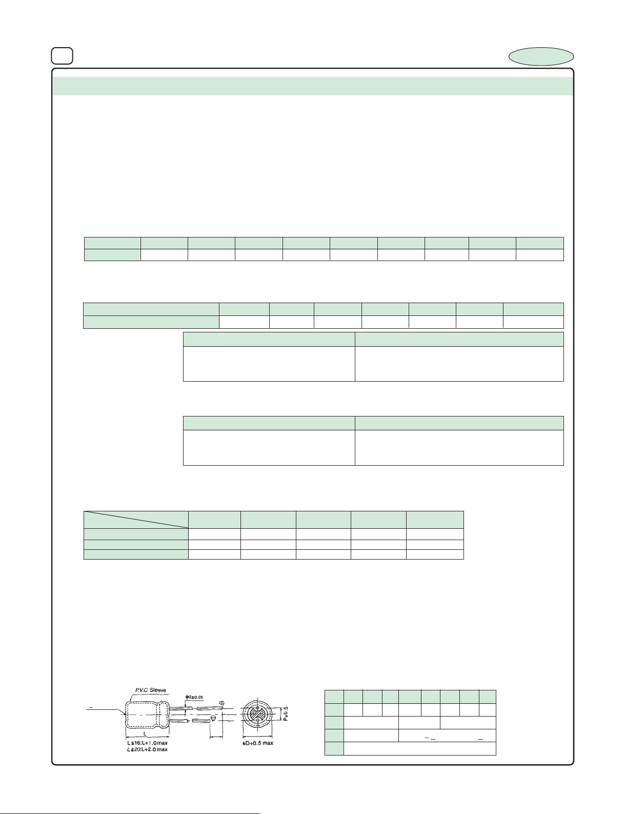
27 ALUMINIUM ELECTROLYTIC CAPACITORS
INCAP
SERIES : LL2
TYPE : Radial - Low Voltage
FEATURES : 1050C, 1000 hours category
SPECIFICATION TABLE :
1. OPERATING TEMPERATURE RANGE : – 40
2. VOLTAGE RANGE : 6.3V - 100 V DC
3. CAPACITANCE RANGE : 0.1µF to 4700 µF
4. CAPACITANCE TOLERANCE at 25
5. LEAKAGE CURRENT at 25
6. DISSIPATION FACTOR (Tan δ) at 250C, 120 Hz :
Voltage
DF
Note : For capacitors whose cap value exceeds 1000 µF, specification of "Tan δ" is increased by 0.02 for every addition of
1000 µF and part of it.
7. TEMPERATURE CHARACTERISTICS (impedance ratio at 120 Hz) :
Rated Voltage
Z(-400C) / Z (+200C)
8. LOAD LIFE TEST :
The Capacitor after load life test for 1000 hrs. at 105
Note : A recovery time of 16 hrs. should be given before taking the measurments after load life test.
9. SHELF TEST :
The Capacitor after shelf test for 500 hrs. at 105
Note : A recovery time of 16 hrs. should be given before taking the measurments after Shelf test.
10. RIPPLE CURRENT & FREQUENCY MULTIPLIERS :
Cap. (µF)
Below 100 0.70 1.00 1.30 1.40 1.50
100 to 1000 0.75 1.00 1.20 1.30 1.35
1000 and above 0.80 1.00 1.10 1.12 1.15
6.3
0.22 0.22 0.20 0.16 0.16 0.16
Freq. (Hz)
0
C, 120 Hz : +_ 20%
0
C (after 3min. Charging) : 0.002 CV or 0.4 µA which ever is greater (
10 16 25 35 40 50 63 100
6.3
12 10 8 6 4 4 3
Test Time 1000 Hrs
Capacitance Change +_ 20% of the initial masured Value
Dissipation Factor Less than 200% of Specified Value
Leakage Current Within specified Value
0
C should meet the above specification
Test Time
Capacitance Change +_ 20% of the initial mesured value
Dissipation Factor Less than 200% of Specified Value
Leakage Current Within specified Value
0
C should meet the above specification
Very Low Leakage type
0
C to 1050 C
10 16 25
1K50012060 (50)
C=Capacitance Value, V=Rated Voltage)
0.14 0.12 0.10
35 40 50 to 100
500 Hrs
≥≥
≥ 10K
≥≥
11. MARKING :
Brand Name, Capacitance Value, Working Voltage, Polarity Marking, Operating Temperature, Month of Manufacture & 'Vent' from
8mm and above.
12. STANDARDS : As per IEC 384-4.
13. DIMENSIONS (NOT TO SCALE) :
LEAD SPACING AND DIAMETER
5 6.3 8 10 13 16 18 22
(>8mm dia)
Vent
5mm
Min
φD
P 2.0 2.5 3.5 5.0 5.0 7.5 7.5 10
φ
d 0.5 0.6 0.8
α
β 0.5
1.0 1.0 for L < 16, 2.0 for L
> 20
Page 30
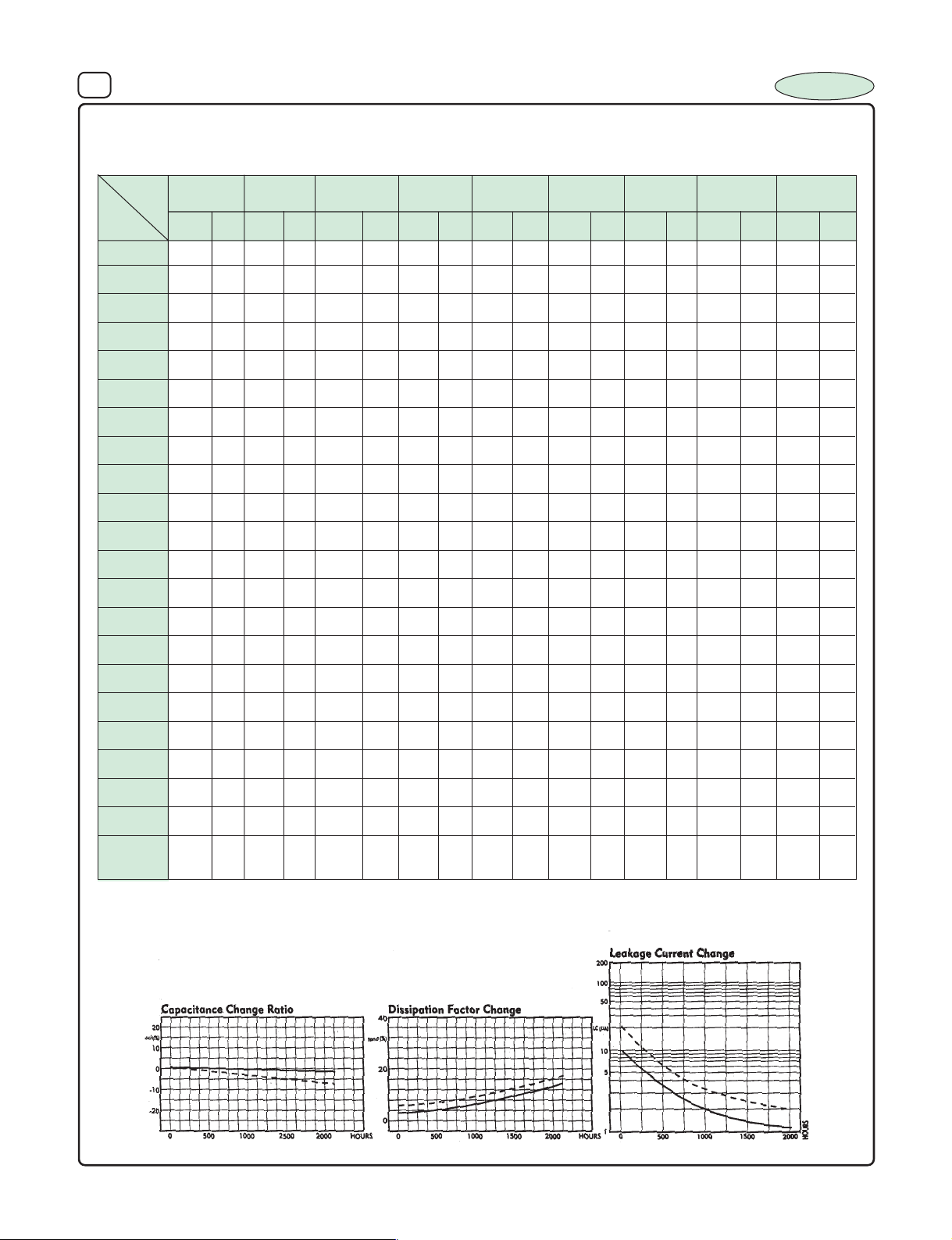
28 ALUMINIUM ELECTROLYTIC CAPACITORS
6.3
W.V .
µF
DxL I
A
0.1
5x11 1.2 5x11 2.3 5x11 2.4
0.22
5x11 2.1 5x11 3.4 5x11 3.75
0.33
5x11 3.8 5x11 5.7 5x11 6.2
0.47
5x11 7 5x11 10.5 5x11 12.5
1
5x11 15 5x11 15 5x11 18
2.2
5x11 23 5x11 25 5x11 26
3.3
5x11 27 5x11 28 5x11 32
4.7
5x11 35 5x11 39 6.3x11 42
10
5x11 35 5x11 41 5x11 44 5x11 47 5x11 48 5x11 50 6.3x11 65
22
. 5x11 60 5x11 63 5x11 71 5x11 75 5x11 78 6.3x11 84 8x11 91
33
5x11 70 5x11 75 6.3x11 82
6.3x11
87 6.3x11 91 8x11 10 8 10x13 130
47
. 5x11 79 5x11 90 5x11 97 6.3x11 115 6.3x11 120 6.3x11 123 8x11 155 10x13 170
100
5x11 111 5x11 125 6.3x11 146 6.3x11 165 8x11 175 8x11 180 8x11 208 10x13 224 13x21 300
150
6.3x11 178 8x11 204.
220
6.3x11
175 6.3x11 190 8x11 260 8x11 270 10x13 300 10x16 325 10x16 330 10x20 365 16x25 534
330
8x11 245 8x11 260 8x11 316 10x16 322 10x16 405 10x20 450 10x20 460 13x21 507 16x32 676
470
8x11 290 8x11 430 10x13 431 10x16 500 10x26 504 10x20 540 13x21 570 13x21 700 16x36 790
1000
10x13 460 10x16 560 10x16 685 13x21 804 13x21 916 16x25 970 16x25 1015 16x32 1150 18x43 1500
1500
10x20 740 13x21 900 13x21 1030 . 18x32 1250 18x37 1350
2200
10x20 840 13x21 935 13x21 1132 16x25 1260 16x32 1530 16x32 1540 18x32 1550 22x37 1600
3300
13x21 1060 13x21 1250 16x25 1475 16x32 1530 18x37 1670 .
4700
16x25 1450 16x25 1500 16x32 1700 18x37 1775 18x43 2000
10
DxL I
A
16
DxL I
A
25
DxL I
A
35
DxL I
A
40
DxL I
A
50
DxL I
A
63
DxL
I
A
100
DxL
I
A
________ 47 µF 25 WV
................ 100
µF 25 WV
14. DIMENSIONS Vs PERMISSIBLE RIPPLE CURRENT :
Dimensions : D x L (mm), Ripple Current (IA): mA/rms at 120 Hz 1050C
INCAP
15. LIFE TEST A T RA TED VOL T A GE AND TEMPERATURE :
Page 31
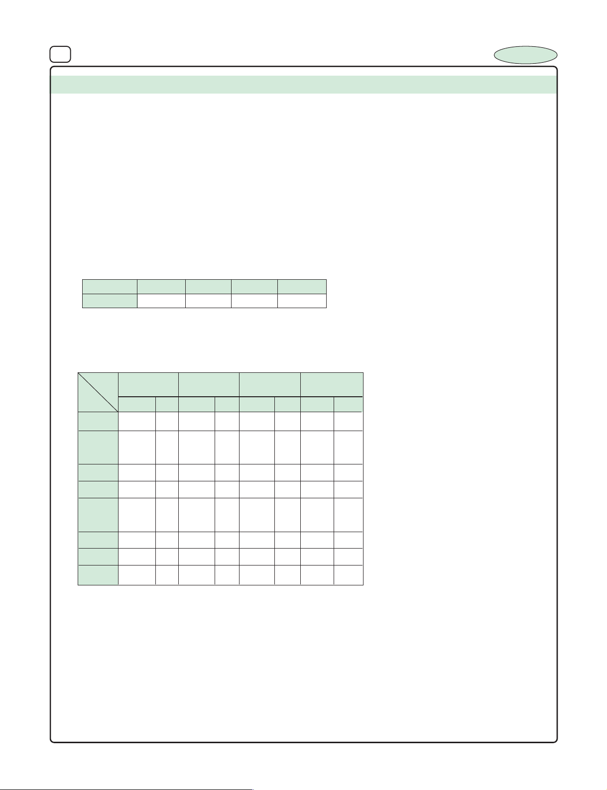
29 ALUMINIUM ELECTROLYTIC CAPACITORS
SERIES : IL 1
TYPE : Radial, medium and high voltage
FEATURES : Low ESR, Long Life
0
2000 Hrs life at 85
SPECIFICATION TABLE :
0
1. OPERATING TEMPERATURE RANGE : – 40
2. VOLTAGE RANGE : 250V - 450 V DC
3. CAPACITANCE RANGE : 3.3 µF to 47 µF
4. CAPACITANCE TOLERANCE at 250C, 120 Hz : +_ 20%
5. LEAKAGE CURRENT at 25
Charging at rated voltage for 3min 0.01 CV (C=Capacitance Value, V=Rated Voltage)
6. DISSIPATION FACTOR (Tan δ) at 250C, 120 Hz :
0
C:
C to 850C
C
INCAP
Voltage
DF
250 350 400
0.15 0.15 0.15
450
0.15
7. DIMENSIONS :
Dimensions : D x L (mm), Ripple Current (IA) : mA/rms at 100 KHz 850C
W.V .
µF
3.3 10x16 82 10x16 92 10x16 115
4.7 10x16 116 10x16 126 10x20 180
6.8 10x20 155 10x20 170 13x21 202
8.2 10x20 170 13x21 185 13x21 230
10 10x20 201 13x21 220 13x21 209 13x21 255
22 13x21 295 13x25 365 13x25 405 16x25 579
33 16x25 410 16x25 440 16x25 540 16x32 607
47 16x25 480 16x32 523 16x36 710 18x37 810
DxL
250
350
I
DxL
A
I
A
400
DxL
10x20 156
I
A
DxL
13x25 289
450
I
A
Rating not covered in this series and for non std.
Sizes contact factory.
Page 32
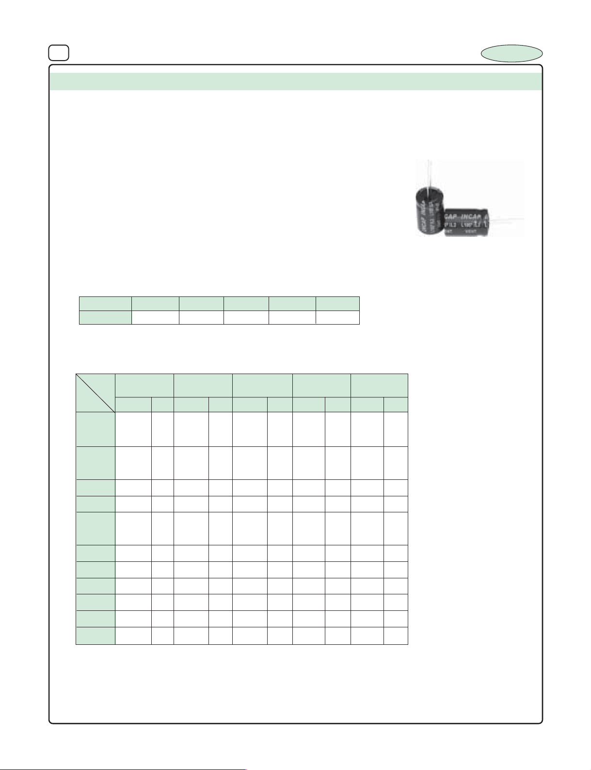
30 ALUMINIUM ELECTROLYTIC CAPACITORS
SERIES : IL 2
TYPE : Radial, medium and high voltage
FEATURES : Low ESR, High Ripple Current, Long Life
Suttable for CFL / BALLAST / INVERTOR /
CONVERTOR and OTHER
HIGH RELIABLE APPLICATIONS.
2000 Hrs Life at 105
SPECIFICATION TABLE :
0
1. OPERATING TEMPERATURE RANGE : – 40
2. VOLTAGE RANGE : 250V - 500 V DC
3. CAPACITANCE RANGE : 3.3 µF to 100 µF
0
4. CAPACITANCE TOLERANCE at 25
5. LEAKAGE CURRENT at 250C:
Charging at rated voltage for 3min 0.006 C V
6. DISSIPATION FACTOR (Tan δ) at 250C, 120 Hz :
C, 120 Hz : +_ 20%
C to 1050C
(C=Capacitance Value, V=Rated Voltage)
0
C
INCAP
Voltage
DF
250 350 400
0.15 0.15 0.15
450
0.12
7. DIMENSIONS :
Dimensions : D x L (mm), Ripple Current (IA) : mA/rms at 100 KHz 1050C
W.V .
µF
3.3 10x16 85 10x16 95 10x16 120
4.7 10x16 120 10x16 130 10x16 190 10x25 168
6.8 10x20 162 10x20 175 13x21 210 13x21 220
8.2 13x21 180 13x21 190 13x21 240 13x25 270
10 10x20 210 13x21 230 13x21 215 13x21 265 13x25 310
22 13x21 310 13x25 380 16x25 502 16x25 600 16x32 500
33 16x23 430 16x25 460 16x25 560 16x32 630
47 16x25 510 16x32 540 16x36 735 18x37 840
68 18x43 1020
82 25x30 1071
100 25x30 1124
250
DxL
350
I
DxL
A
I
A
400
DxL
10x26 120 10x20 150
10x20 160 10x20
13x25 240 13x25 300
I
DxL
A
500
450
0.12
I
A
DxL
500
I
A
Rating not covered in this series and for non std.
Sizes contact factory.
Page 33
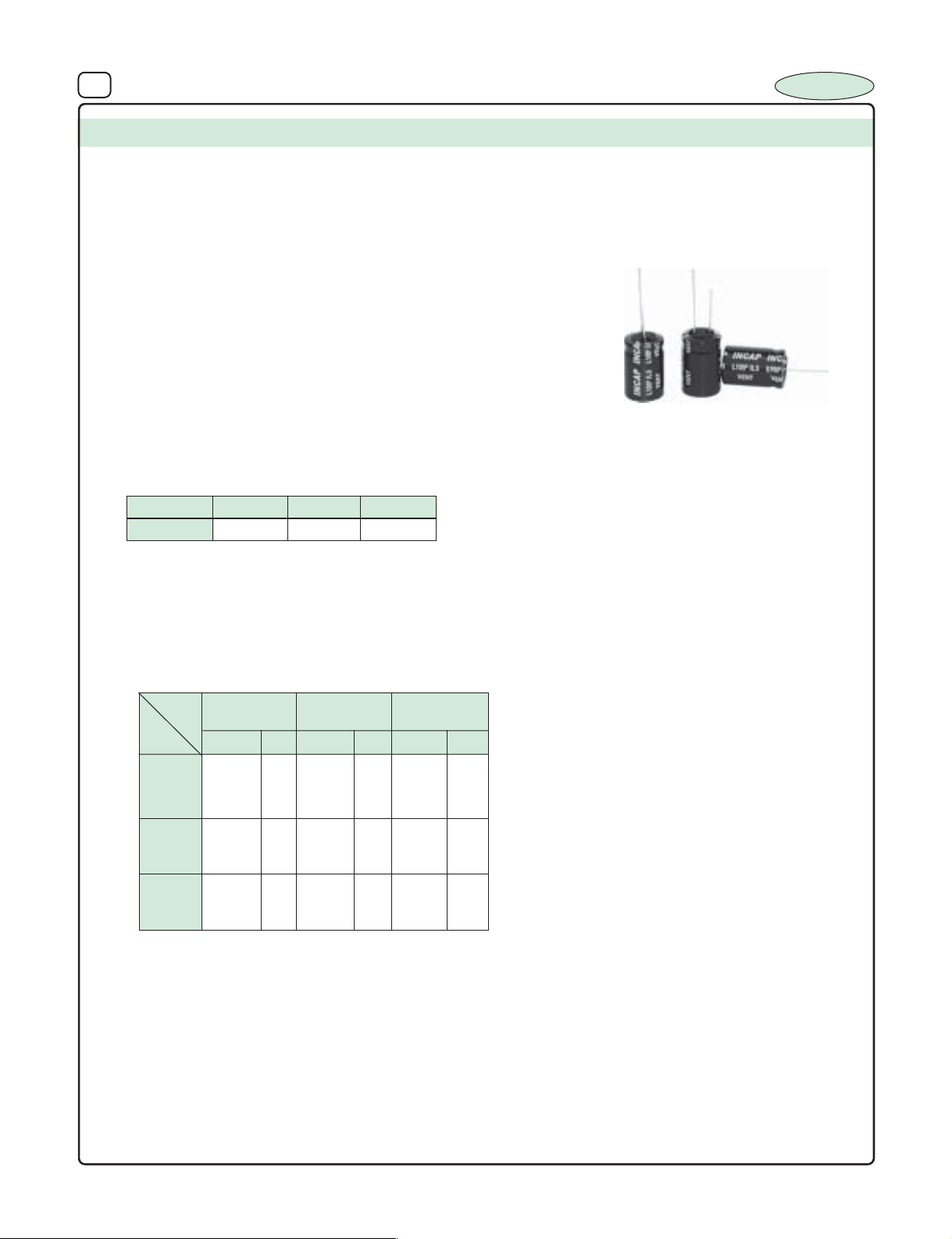
31 ALUMINIUM ELECTROLYTIC CAPACITORS
SERIES : IL 5
TYPE : Radial low, medium and high voltage
FEATURES : Low ESR, Extremely Low Impedence Extended Long Life
High Reliability. Suttable for CFL / BALLAST / INVERTOR /
CONVERTOR and OTHER HIGH RELIABLE APPLICATIONS.
2000 Hrs Life at 105
5000 hrs life at 1050C
SPECIFICATION TABLE :
0
1. OPERATING TEMPERATURE RANGE : – 40
2. VOLTAGE RANGE : 350V - 450 V DC
3. CAPACITANCE RANGE : 3.3 µF to 10 µF
4. CAPACITANCE TOLERANCE at 250C, 120 Hz : +_ 20%
5. LEAKAGE CURRENT at 250C:
Charging at rated voltage for 3min 0.006 CV
6. DISSIPATION FACTOR (Tan δ) at 250C, 120 Hz :
C to 1050C
(C=Capacitance Value, V=Rated Voltage)
0
C
INCAP
Voltage
DF
350 400
0.15 0.12
7. DIMENSIONS :
Dimensions : D x L (mm), Ripple Current (I
W.V .
µF
3.3 10x20 88 10x20 125 10x20 154
4.7 10x20 125 10x20 165 10x25 195
10 13x25 240 13x25 248 16x25 315
350
DxL
400
I
DxL
A
450
0.10
) : mA/rms at 100 KHz 1050C
A
450
DxL
I
A
I
A
Rating not covered in this series and for non std.
Sizes contact factory.
Page 34
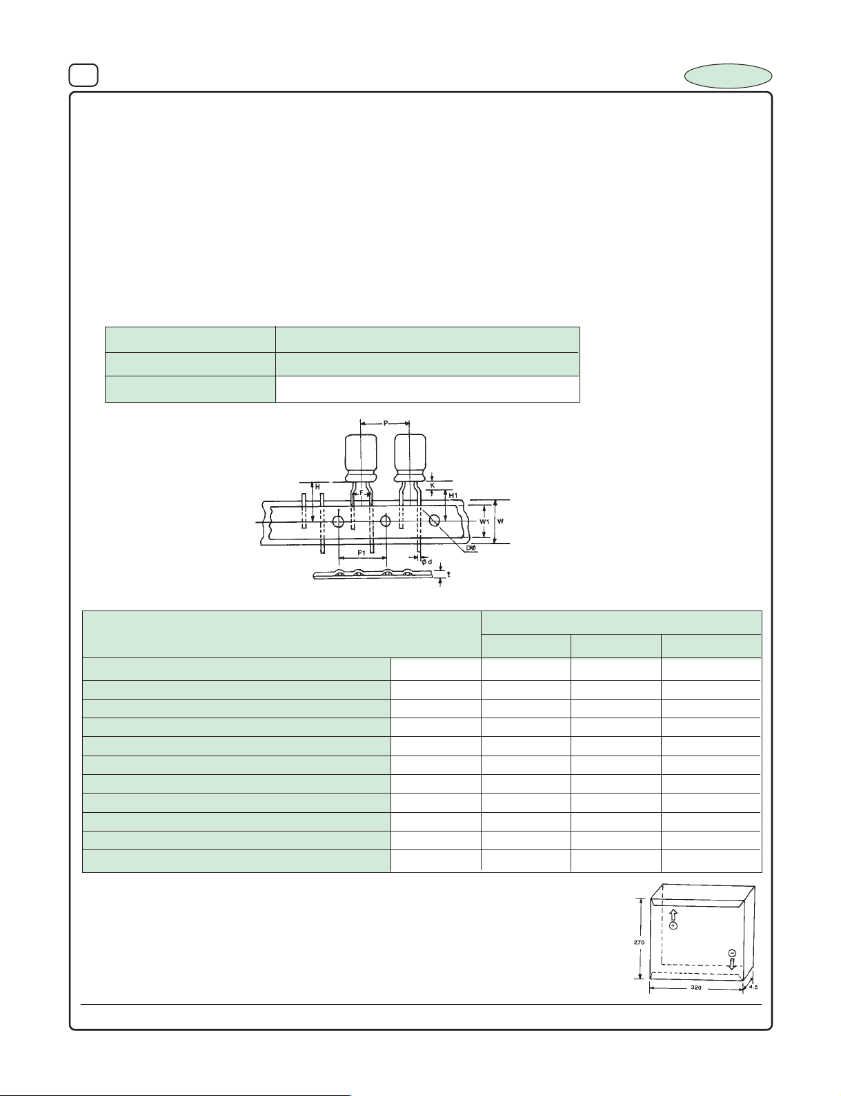
32 ALUMINIUM ELECTROLYTIC CAPACITORS
SPECIFICATIONS FOR TAPING
1. Scope :
This standard describes the process of lead taping & packaging for taped Radial Aluminium electrolytic Capacitors for
Automatic Insertion System.
2. Features :
2.1 By use of special adhesive tapes and backing paper leadwires are firmly held, for self supported stay insertion in
boards.
2.2. Available for capacitor sizes of 5x11, 6.3x11, 8x11 and 10x13.
2.3. Capacitors are provided in lead formed and straight lead as per the specific requirements.
(if mentioned as taped then the capacitors are lead formed and taped to 5mm pitch)
3. Packaging :
Ammo packs are arranged for out feed for either end polar ity marked on the packaging to feed (plus) + first or
(minus) –first.
4.
Ammo Pack
Case Size 5x11 6x11 8x11 10x13
Qty per Pack 2000 1500 1000 600
Lead Taping Dimensions :
5.1 Figure
INCAP
5.2 Dimension : in mm
Item
5x11
Lead wire Diameter φd +/- 0.05 0.5 0.5 0.5
Pitch of component P +/- 1.0 12.7 12.7 12.7
Feed hole pitch P1 +/- 0.3 12.7 12.7 12.7
Lead to lead distance F +/- 0.5 5.0 5.0 5.0
Clinch height K 2.5 2.5 2.5h
Height of component from tape centre H 18.5 18.5 20.0
Lead wire clinch height H1 +/- 0.5 16.0 16.0 16.0
Tape width W 18.0 18.0 18.0
Hold down tape width W1 +/- 0.3 13.0 13.0 13.0
Feed hole diameter φD +/- 0.2 4.0 4.0 4.0
Total tape thickness t +/- 0.2 0. 7 0. 7 0.7
Size
6x11 8x11
6. PACKAGING : (Dimensions are in mm)
6.1 Ammo Pack
Note : Contact Factor y for Stright lead taped capacitors specification.
Design, specifications are subject to change without notice.
Page 35
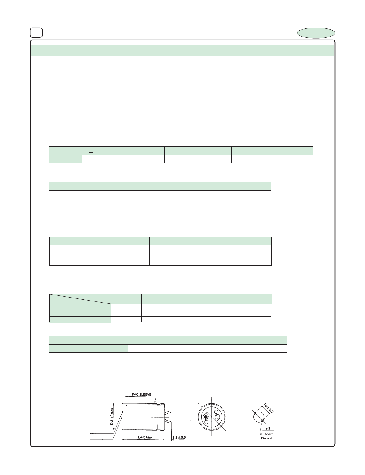
33 ALUMINIUM ELECTROLYTIC CAPACITORS
SERIES : IS 1
TYPE : Snap-in
FEATURES : General Pur pose Snap-in Capacitors for direct PCB mounting
SPECIFICATION TABLE :
1.
OPERATING TEMPERATURE RANGE
2. VOLTAGE RANGE : 25V to 100 VDC 160V to 450VDC
3. CAPACITANCE RANGE : 3300 µF to 15000 µF 47~ 1000µF
0
4. CAPACITANCE TOLERANCE at 25
5. LEAKAGE CURRENT (I) : 0.06CV+200µA or 3mA which ever is smaller
(Charging at rated voltage for 5min.)
6. DISSIPATION FACTOR (Tan δ) at 250 C, 120 Hz :
Voltage
DF
Note : The above value increase by 0.02 for every additional 1000µF and part of it.
7. LOAD LIFE TEST :
< 25
0.25 0.20 0.20 0.20 0.15 0.15 0.15
C, 120 Hz : +_ 20%
35 50 63
Test Time 2000 Hrs
Capacitance Change +_ 20% of the initial masured Value
Dissipation Factor Less than 200% of Specified Value
Leakage Current Within specified Value
The Capacitor after load life test for 2000 hrs. at 85
Note : A recovery time of 16 hrs. should be given before taking the measur ments after load life test.
8. SHELF TEST :
0
C should meet the above specification
Test Time
Capacitance Change +_ 20% of the initial mesured value
Dissipation Factor Less than 200% of Specified Value
Leakage Current Within specified Value
0
The Capacitor after shelf test for 1000 hrs. at 85
Note : A recovery time of 16 hrs. should be given before taking the measur ments after shelf test.
9. RIPPLE CURRENT & FREQUENCY MULTIPLIERS :
Cap. (µF)
Below 100 0.90 1.00 1.07 1.15 1.15
100 to 1000 0.88 1.00 1.07 1.15 1.20
1000 and above 0.90 1.00 1.03 1.10 1.15
Freq. (Hz)
C should meet the above specification
:– 400 C to 850C –250C to +850C
I : Leakage current (µA) C : Rated Capacitance (µF) V : Rated Voltage (V)
80 ~ 100
160 ~ 250 350 ~ 450
1000 Hrs
1K30012050 (60)
>10K
INCAP
10. RIPPLE CURRENT & TEMPERATURE MULTIPLIERS :
Temperature (0C)
Multiplier
11. MARKING :
Brand name, Capacitance Value, Working Voltage, Polarity marking, Operating Temperature and month of manufacture.
12. DIAGRAM DIMENSIONS (Not to scale) :
Safety vent
Insulation disc
Below 40
1.8 1
60
1.4
70
1.2
85
Page 36
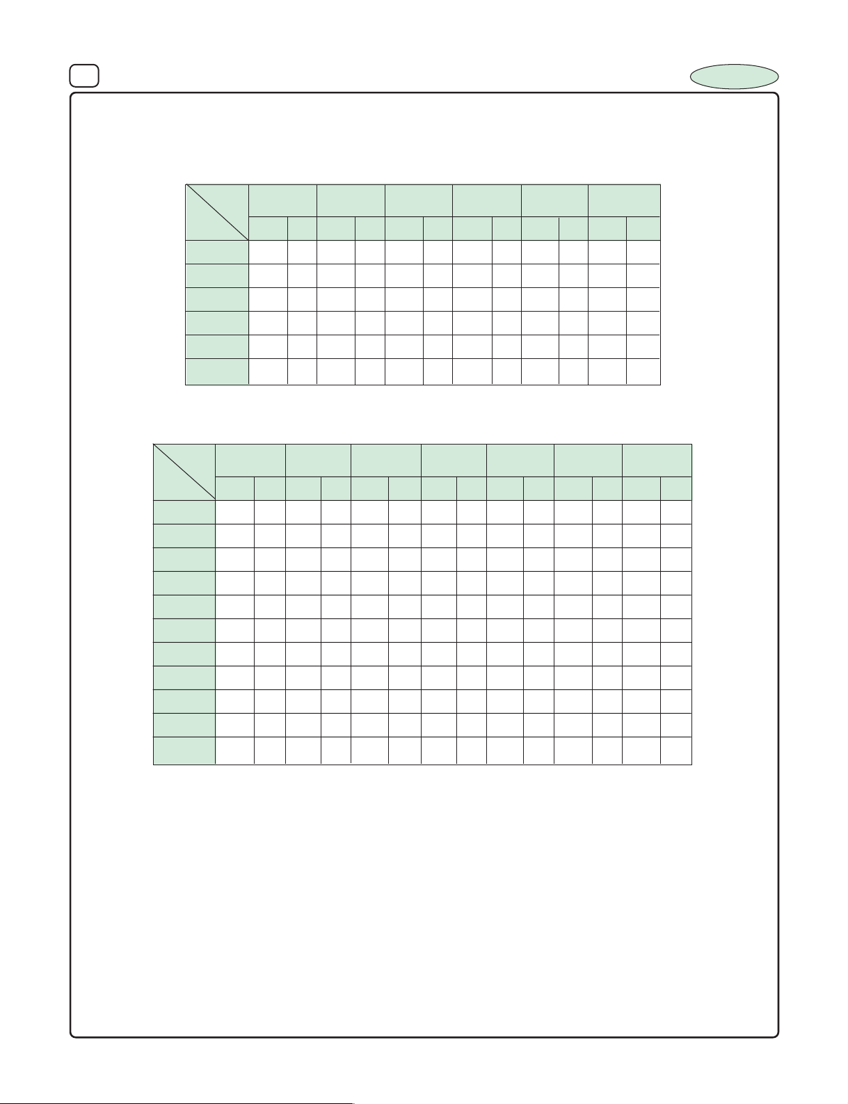
34 ALUMINIUM ELECTROLYTIC CAPACITORS
13. DIMENSIONS Vs PERMISSIBLE RIPPLE CURRENT :
Dimensions : D x L (mm), Ripple Current (IA): mA/rms at 120 Hz 850C
INCAP
µF
µF
W.V .
47
68
100
150
W.V .
3300
4700
5000
6800
10000
15000
DxL
25
I
DxL
22x43 2000 25x25 2400 22x43 3000 25x50 3200
25x40 2100 25x40 2500 25x50 3100 30x50 3700 35x52 4700
30x35 2900 30x35 3000 25x50 3700 35x45 4300
30x40 3200 30x50 3600 30x50 4900
160
I
DxL
A
35
I
DxL
A
35x52 4500 30x50 5100 35x52 6300
200
I
DxL
A
A
250
DxL
I
A
40
I
DxL
A
22x37 2700 25x40 2700
350
DxL
50
I
I
DxL
A
25x25 430 25x25 460 25x25 500
22x37 620 22x37 680 25x30 800
22x37 900 22x37 960 25x30 1100
25x40
A
400
63
I
DxL
DxL
A
420
I
A
1200
I
DxL
25x40 1250 25x50 1300
100
A
I
A
DxL
450
I
A
220
270
330
390
470
560
1000
22x37
1000 25x30 1200 25x30 1280 25x50 1360 25x50 1575 25x50 1600 25x60 1625
30x50 1700
25x40 1400 25x40 1600 30x40 1650 30x50 1790 35x45 1950 35x45 2000 35x45 2100
35x52 2350
25x40 1900 25x40 1950 25x50 2100 35x52 2200 35x52 2500 35x52 2550 35x52 2650
25x60 2050 25x50 2150 35x50 2300 35x52 2450
35x45 3000 35x52 3300
Page 37
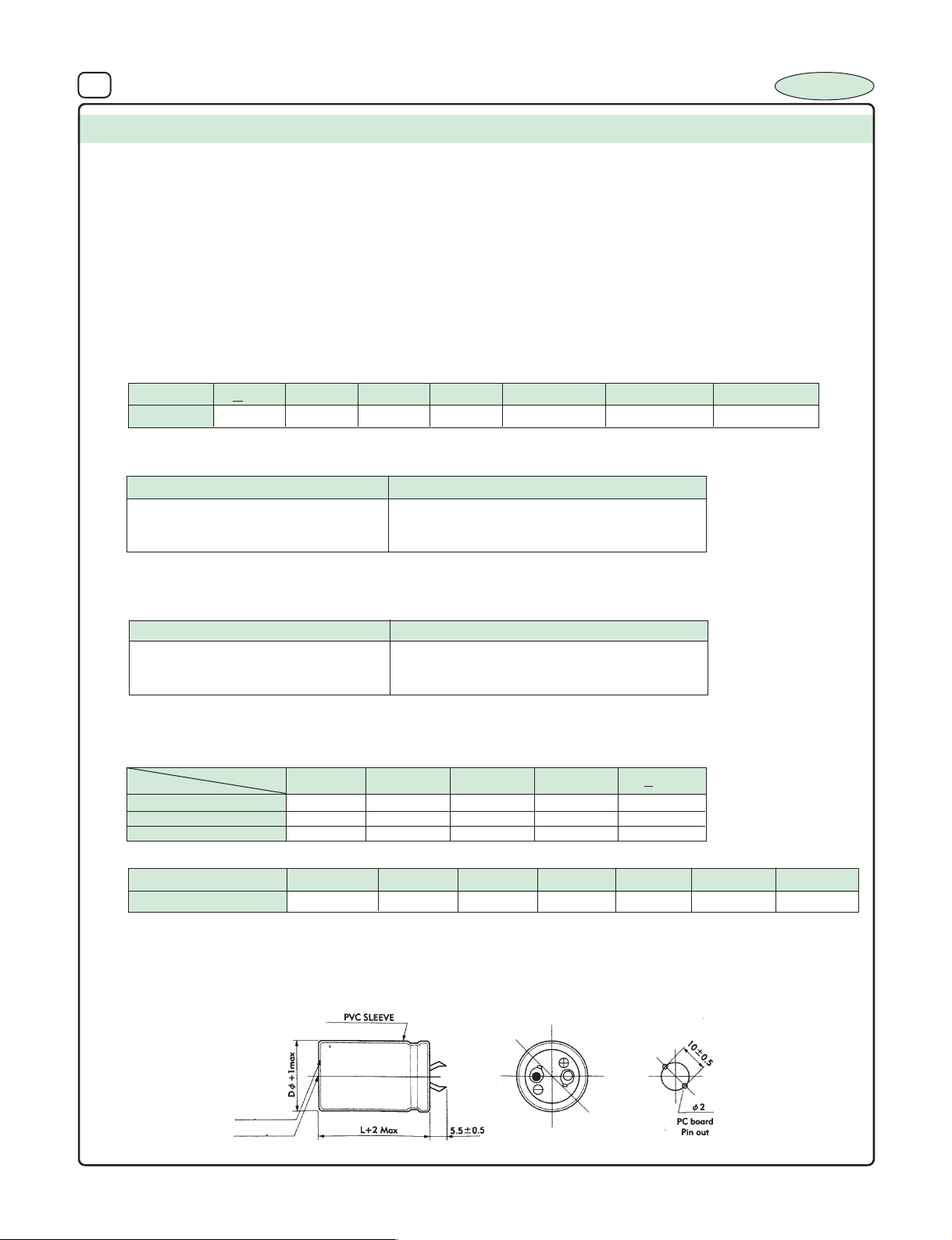
37 ALUMINIUM ELECTROLYTIC CAPACITORS
SERIES : IS 2
TYPE : Snap-in
FEATURES : General Pur pose Snap-in Capacitors for direct PCB mounting
SPECIFICATION TABLE :
OPERATING TEMPERATURE RANGE
1.
2. VOLTAGE RANGE : 25V to 100 VDC 160V to 450VDC
3. CAPACITANCE RANGE : 3300 µF to 15000 µF 47~ 1000µF
4. CAPACITANCE TOLERANCE at 250C, 120 Hz : +_ 20%
5. LEAKAGE CURRENT : 0.06CV+200µA or 3mA which ever is smaller
(Charging at rated voltage for 5min.)
6. DISSIPATION FACTOR (Tan δ) at 250 C, 120 Hz :
:– 250C to 1050C –250C to +1050C
I : Leakage Current (µA) C : Rated Capacitance (µF) V : Rated Voltage (V)
INCAP
Voltage
DF
Note : The above value increase by 0.02 for every additional 1000µF and part of it.
7. LOAD LIFE TEST :
< 25
35 50 63 80 ~ 100 160 ~ 250 350 ~ 450
0.25 0.20 0.20 0.20 0.15 0.15 0.15
Test Time 1000 Hrs
Capacitance Change +_ 20% of the initial masured Value
Dissipation Factor Less than 200% of Specified Value
Leakage Current Within specified Value
0
The Capacitor after load life test for 1000 hrs. at 105
Note : A recovery time of 16 hrs. should be given before taking the measurments after load life test.
8. SHELF TEST :
Test Time
Capacitance Change +_ 20% of the initial mesured value
Dissipation Factor Less than 200% of Specified Value
Leakage Current Within specified Value
The Capacitor after shelf test for 500 hrs. at 105
Note : A recovery time of 16 hrs. should be given before taking the measurments after shelf test.
9. RIPPLE CURRENT & FREQUENCY MULTIPLIERS :
Cap. (µF)
Below 100 0.90 1.00 1.07 1.15 1.15
100 to 1000 0.88 1.00 1.07 1.15 1.20
1000 and above 0.90 1.00 1.03 1.10 1.15
10. RIPPLE CURRENT & TEMPERATURE MULTIPLIERS :
Temperature (0C)
Multiplier
11. MARKING :
Brand name, Capacitance Value, Working Voltage, Polarity marking, Operating Temperature and month of manufacture.
12. DIAGRAM DIMENSIONS (Not to scale) :
Freq. (Hz)
Below 40
1.9 1.6 1.35
C should meet the above specification
500 Hrs
0
C should meet the above specification
50
1.8
60
1.7
1K30012050 (60)
> 10K
70 85
90
1.25
105
1.0
Safety vent
Insulation disc
Page 38
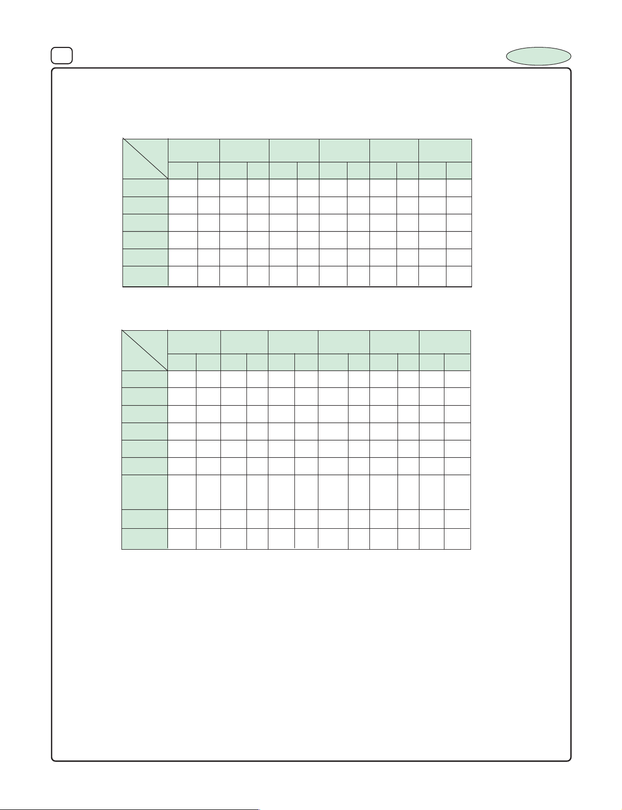
36 ALUMINIUM ELECTROLYTIC CAPACITORS
13. DIMENSIONS Vs PERMISSIBLE RIPPLE CURRENT :
Dimensions : D x L (mm), Ripple Current (IA) : mA/rms at 120 Hz 1050C
INCAP
µF
µF
W.V .
3300
4700
5000
6800
10000
15000
W.V .
47
68
100
150
25
I
DxL
22x43 1450 25x25 1500 22x43 2100 25x50 2400
25x40 1500 25x40 1600 25x50 2200 30x50 2450 35x52 2950
30x35 1700 30x35 1950 25x50 2500 35x45 2700
30x40 2200 30x50 2500 30x50 3300
160
I
DxL
A
35
I
DxL
A
35x52 3350 30x50 3400 35x52 3500
200
I
DxL
A
40
I
DxL
A
DxL
A
22x37 1750 25x40 2050 30x60 2750
250
I
DxL
DxL
A
25x25 380 25x25 390 25x25 410
22x37 450 22x37 470 25x30 500
22x37 750 25x30 760 25x40 780
25x40
50
400
63
I
A
DxL
I
A
420
I
A
810
25x40 825 25x50 850
DxL
I
A
DxL
DxL
100
450
I
A
I
A
220
330
470
560
1000
22x37
25x40 1110 25x40 1200 30x40 1350 35x45 1385 35x45 1420 35x45 1520
25x40 1320 25x40 1410 25x50 1600 35x52 1760 35x52 1800 35x52 1840
25x50 1410 25x50 1600 35x50 1750 35x60 1820 35x60 1930
35x45 2100 35x52 2200
800 25x30 850 25x30 910 25x50 1020 25x50 1030 25x60 1060
30x50 1632
Page 39
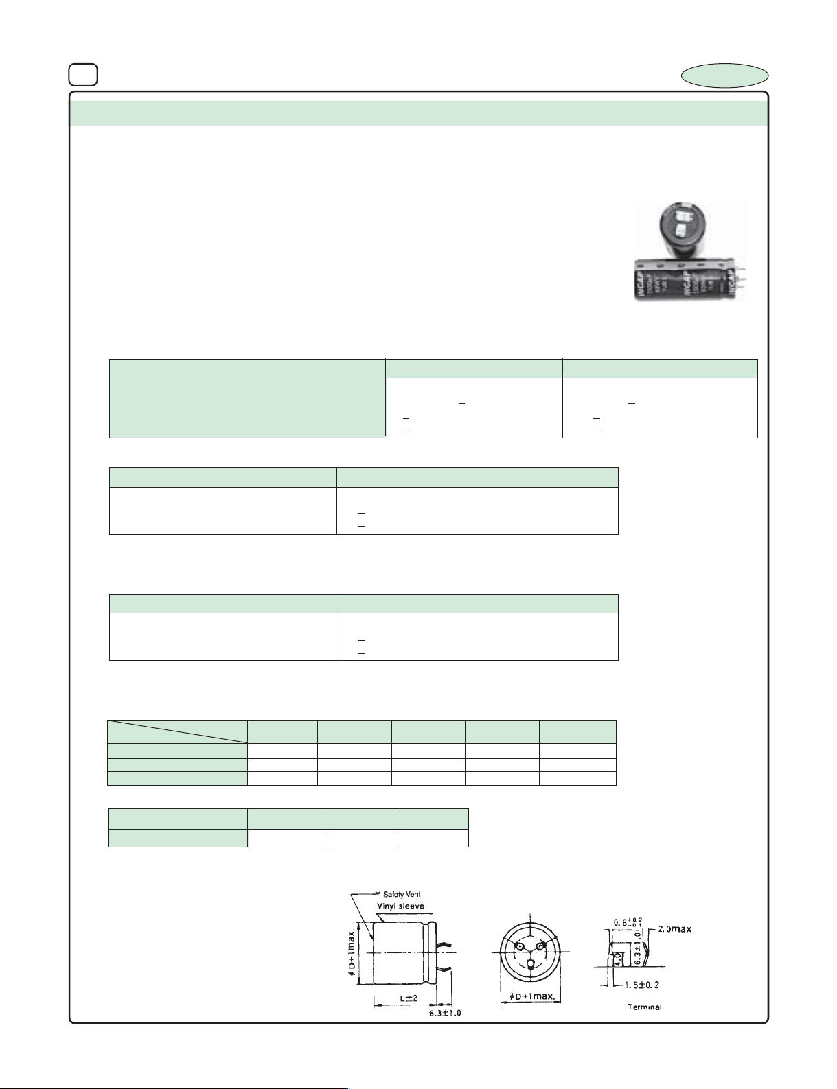
37 ALUMINIUM ELECTROLYTIC CAPACITORS
SERIES : TUB-5
TYPE : Snap-in
0
FEATURES : 105
SPECIFICATION TABLE :
OPERATING TEMPERATURE RANGE
1.
2. VOLTAGE RANGE : 10V to 100 VDC
3. CAPACITANCE RANGE : 180 µF to 15000 µF
4. CAPACITANCE TOLERANCE at 250C, 120 Hz : - 10% to +75%
5. LEAKAGE CURRENT : 0.004CV at +250C
(Charging at rated voltage for 5min.)
6. TEMPERATURE CHARACTERISTICS :
Impedance ratio 6max. 1max
Capacitance Change
ESR
Leakage current
7. LOAD LIFE TEST :
Test Time
Capacitance Change +_ 20% of the initial measured Value
ESR
Leakage Current
< 300% of Specified Value
< initial Specified Value
C, 3 Terminal large tubuler extended long life low ESR , Low
Impendence Capacitors for Stable and reverse proof mounting.
Suitable for high reliable inver tor and convertor applications
:– 550C to +1050C
I : Leakage Current (µA) C : Rated Capacitance (µF) V : Rated Voltage (V)
At 120Hz, -55
+35% +15%
< 20 x initial specified value < initial specified value
< initial specified value < 5 x initial specified value
5000 Hrs
INCAP
0
C/+200C At 120Hz, -1050C/+200C
The Capacitor after load life test for 5000 hrs. at 1050C should meet the above specification
Note : A recovery time of 16 hrs. should be given before taking the measurments after load life test.
8. SHELF TEST :
Test Time
Capacitance Change +_ 20% of the initial mesured value
ESR
Leakage Current
The Capacitor after shelf test for 1000 hrs. at 1050C should meet the above specification
Note : A recovery time of 16 hrs. should be given before taking the measurments after shelf test.
9. RIPPLE CURRENT & FREQUENCY MULTIPLIERS :
DC Voltage
10 to 16V 0.65 0.75 0.78 0.80 1.0
25 to 50V 0.45 0.60 0.70 0.75 1.0
63 to 100V 0.28 0.50 0.65 0.75 1.0
10. RIPPLE CURRENT & TEMPERATURE MULTIPLIERS :
Temperature (0C)
Multiplier
11. MARKING :
Brand name, Capacitance Value, Working Voltage, Polar ity mar king, Operating Temperature and month of manufacture.
12. DIAGRAM DIMENSIONS (Not to scale) :
Freq. (Hz)
+650C
1.36
< 200% of Specified Value
< 5 x initial specified Value
+850C
+1050C
1.0
0.35
1000 Hrs
1K30012050 (60)
20K
Page 40
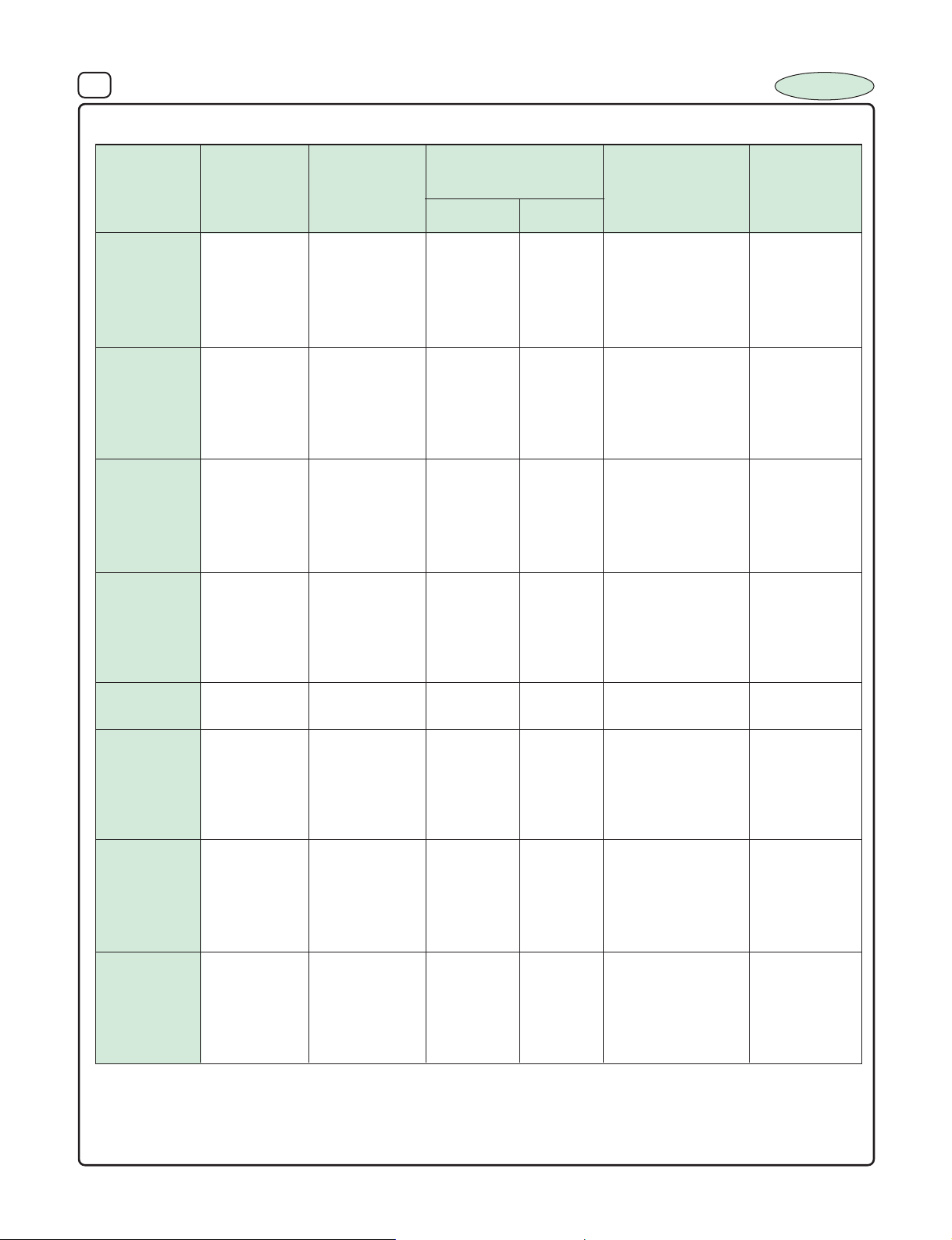
40 ALUMINIUM ELECTROLYTIC CAPACITORS
INCAP
13. DIMENSIONS Vs ESR, IMPEDENCE and RIPPLE CURRENT
Rated Capacitance Nominal Maximum ESR Maximum Maximum
Voltage (µF) Case Size* (Ω) at + 250C Impedance Ripple Current
(WVDC) DxL (mm) (Ω) at (A rms) at
120Hz 10KHz +25
3300 22x37 0.054 0.0309 0.0305 4.53
5600 22x43 0.027 0.0160 0.0177 6.58
10 4700 25x30 0.039 0.0272 0.0273 5.04
13 V Surge 6800 25x40 0.030 0.0141 0.0170 7.40
10000 25x50 0.017 0.0105 0.0148 9.01
15000 25x64 0.012 0.0080 0.0129 11.04
2200 22x37 0.072 0.0312 0.0308 4.50
3300 22x43 0.048 0.0162 0.0179 6.55
16 2700 25x30 0.058 0.0274 0.0276 5.01
20 V Surge 4700 25x40 0.038 0.0142 0.0172 7.37
6800 25x50 0.026 0.0106 0.0150 8.97
10000 25x64 0.017 0.0081 0.0130 10.98
1000 22x37 0.111 0.0315 0.0311 4.48
1800 22x43 0.062 0.0163 0.0181 6.52
25 1500 25x30 0.078 0.0277 0.0279 4.99
32 V Surge 2700 25x40 0.046 0.0144 0.0173 7.33
3900 25x50 0.030 0.0108 0.0157 8.93
4700 25x64 0.025 0.0082 0.0131 10.93
820 22x37 0.111 0.0318 0.0314 4.46
1500 22x43 0.062 0.0165 0.0182 6.49
35 1200 25x30 0.078 0.0280 0.0281 4.97
44 V Surge 1800 25x40 0.046 0.0145 0.0175 7.30
2700 25x50 0.030 0.0109 0.0153 8.88
3900 25x64 0.025 0.0082 0.0132 10.88
40 1500 25x40 0.040 0.0170 0.0182 5.6
50 V Surge 2700 25x64 0.034 0.0160 0.0153 7.2
560 22x37 0.173 0.0832 0.0780 2.76
820 22x43 0.118 0.0432 0.0411 4.01
50 680 25x30 0.146 0.0767 0.0715 3.00
63 V Surge 1200 25x40 0.083 0.0398 0.0389 4.41
1500 25x50 0.066 0.0298 0.0305 5.37
2200 25x64 0.045 0.0226 0.0242 6.57
330 22x37 0.201 0.0857 0.0791 2.72
560 22x43 0.118 0.0445 0.0417 3.95
63 470 25x30 0.146 0.0790 0.0736 2.96
79 V Surge 680 25x40 0.104 0.0410 0.0401 4.34
1000 25x50 0.071 0.0306 0.0314 5.29
1500 25x64 0.047 0.0233 0.0249 6.47
180 22x37 0.302 0.0907 0.0812 2.64
270 22x43 0.201 0.0470 0.0428 3.84
100 220 25x30 0.273 0.0836 0.0779 2.87
125 V Surge 390 25x40 0.156 0.0434 0.0425 4.22
560 25x50 0.104 0.0324 0.0333 5.14
820 25x64 0.086 0.0246 0.264 6.29
*The case sizes in table are with no sleeve, refer to diagrams for case sizes with sleeve
0
C, 100KHz +850C, 20KHz
Page 41
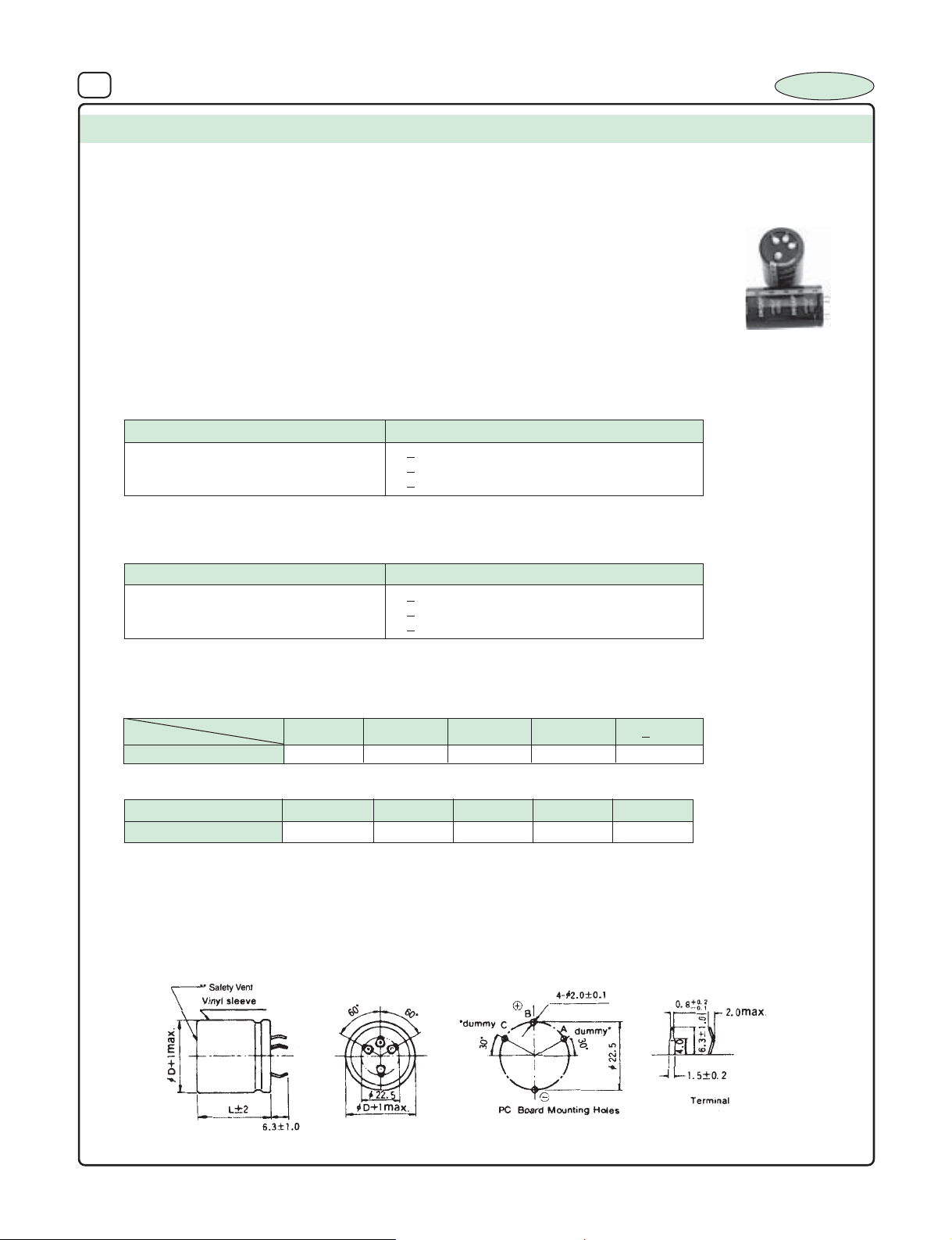
41 ALUMINIUM ELECTROLYTIC CAPACITORS
SERIES : IS2-4T
TYPE : Snap-in, Low voltage
0
FEATURES : 105
SPECIFICATION TABLE :
OPERATING TEMPERATURE RANGE
1.
2. VOLTAGE RANGE : 25V to 100 VDC
3. CAPACITANCE RANGE : 400 µF to 56000 µF
4. CAPACITANCE TOLERANCE at 250C, 120 Hz : - 0% to +30%
5. LEAKAGE CURRENT : 0.006CV at +250C
(Charging at rated voltage for 5min.)
(V)
6. LOAD LIFE TEST :
:– 400C to +1050C
Test Time 2000 Hrs
Capacitance Change < +_ 20% of the initial measured Value
ESR
Leakage Current
The Capacitor after load life test for 2000 hrs. at 105
Note : A recovery time of 16 hrs. should be given before taking the measurments after load life test.
7. SHELF TEST :
< 200% of Specified Value
< initial Specified Value
0
C should meet the above specification
Test Time
Capacitance Change < +_ 20% of the initial mesured value
ESR
Leakage Current
The Capacitor after shelf test for 1000 hrs. at 105
Note : A recovery time of 16 hrs. should be given before taking the measurments after shelf test.
< 200% of Specified Value
< 5 x initial specified Value
0
C should meet the above specification
C, Longer life High Ripple capability and better stability in
mounting for Invertor and Convertor applications
4 Terminal type Capacitors
I : Leakage Current (µA) C : Rated Capacitance (µF) V : Rated Voltage
1000 Hrs
INCAP
8. RIPPLE CURRENT & FREQUENCY MULTIPLIERS :
DC Voltage
25 to 100V 0.93 1.00 1.05 1.08 1.15
9. RIPPLE CURRENT & TEMPERATURE MULTIPLIERS :
Temperature (0C)
Multiplier
10. MARKING :
Brand name, Capacitance Value, Working Voltage, Polar ity mar king, Operating Temperature and month of manufacture.
11. DIAGRAM DIMENSIONS (Not to scale) :
Freq. (Hz)
+450C
2.35
+600C
2.2
+700C
2.0
1K50012050 (60)
+850C +1050C
1.7
> 10K
1.0
Page 42
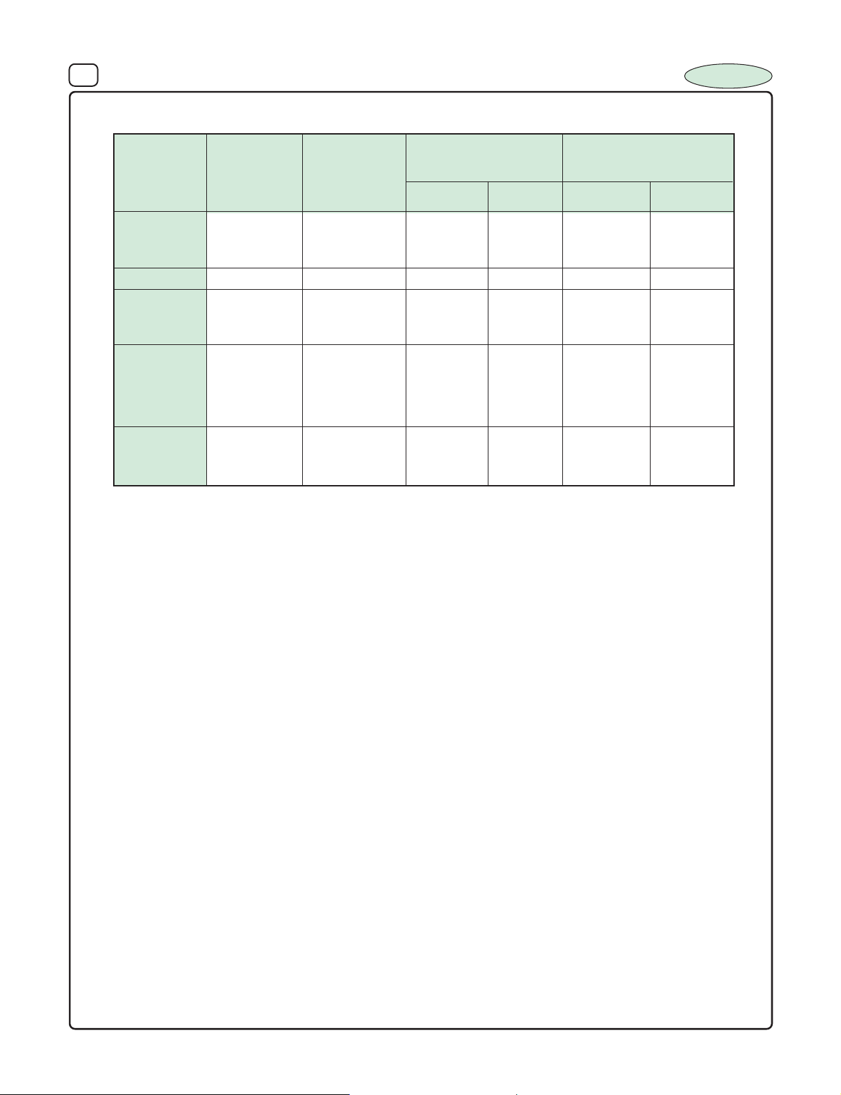
40 ALUMINIUM ELECTROLYTIC CAPACITORS
12. DIMENSIONS Vs ESR and RIPPLE CURRENT
Rated Capacitance Nominal Maximum ESR Maximum Ripple Current
Voltage (µF) Case Size (Ω) at + 250C (A rms) at +850C
(WVDC) DxL (mm)
120Hz 20KHz 120Hz 20KHz
33000 40x40 0.018 0.016 9.35 10.75
25 47000 40x50 0.019 0.015 10.50 12.07
56000 40x63 0.015 0.012 11.40 13.11
35 22000 40x40 0.023 0.017 8.5 9.77
15000 40x40 0.022 0.018 8.16 9.38
50 22000 40x50 0.026 0.019 8.67 9.97
27000 40x63 0.021 0.016 9.52 10.95
*4000 35x63 0.016 0.011 13.9 15.6
4700 40x40 0.020 0.018 6.5 7.47
63 12000 40x40 0.03 0.028 7.68 8.83
15000 40x50 0.033 0.025 7.82 8.99
18000 40x63 0.028 0.020 8.50 9.77
4700 40x40 0.053 0.04 6.46 7.43
100 6800 40x50 0.049 0.038 7.14 8.21
8200 40x63 0.040 0.030 7.8 8.97
INCAP
*Specially Designed to match the specification of popular MNC
Page 43
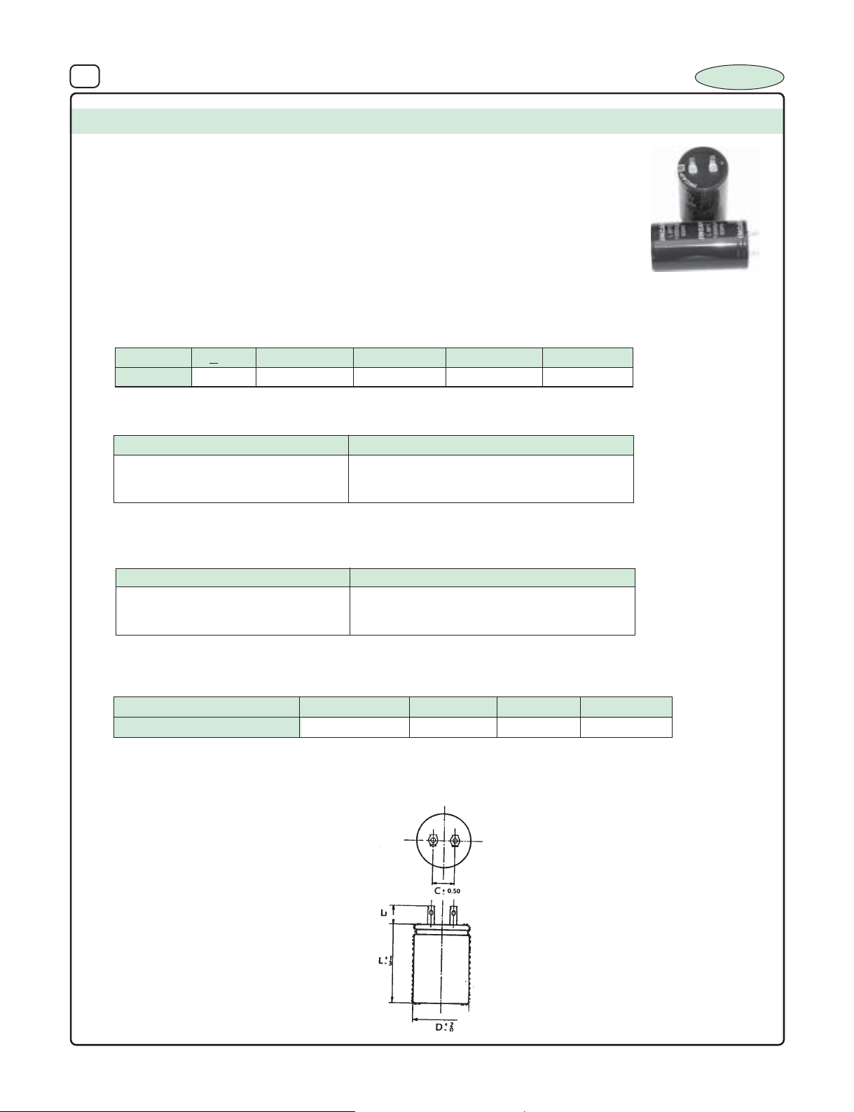
41 ALUMINIUM ELECTROLYTIC CAPACITORS
SERIES : LT 1
TYPE : Lug Terminal
FEATURES : 85
SPECIFICATION TABLE :
OPERATING TEMPERATURE RANGE
1.
2. VOLTAGE RANGE : 25V to 100 VDC 160V to 450VDC
3. CAPACITANCE RANGE : 1000 µF to 33000 µF 470 ~ 2200µF
4. CAPACITANCE TOLERANCE at 250C, 120 Hz : +_ 20%
5. LEAKAGE CURRENT (I) : 0.06CV+200µA or 3mA which ever is smaller
(Charging at rated voltage for 5min.)
6. DISSIPATION FACTOR (Tan δ) at 250 C, 120 Hz :
0
C, General Purpose
:– 400 C to 850C –25 to +850C
I:Leakage Current (µA) C : Rated Capacitance (µF) V : Rated Voltage (V)
INCAP
Voltage
DF
Note : The above value increase by 0.02 for every additional 1000µF and part of it.
7. LOAD LIFE TEST :
< 25
35 ~ 63 80 ~ 100 160 ~ 250 350 ~ 450
0.25 0.20 0.15 0.15 0.15
Test Time 1000 Hrs
Capacitance Change +_ 20% of the initial masured Value
Dissipation Factor Less than 200% of Specified Value
Leakage Current Within specified Value
The Capacitor after load life test for 1000 hrs. at 85
Note : A recovery time of 16 hrs. should be given before taking the measurments after load life test.
8. SHELF TEST :
Test Time
Capacitance Change +_ 20% of the initial mesured value
Dissipation Factor Less than 200% of Specified Value
Leakage Current Within specified Value
The Capacitor after shelf test for 500 hrs. at 85
Note : A recovery time of 16 hrs. should be given before taking the measurments after shelf test.
9. RIPPLE CURRENT & TEMPERATURE MULTIPLIERS :
Temperature (0C)
Multiplier 1.8
10. MARKING :
Brand name, Capacitance Value, Working Voltage, Polarity marking, Operating Temperature and month of manufacture.
11. DIAGRAM DIMENSIONS (Not to scale) :
0
C should meet the above specification
500 Hrs
0
C should meet the above specification
Below 40
60
1.4
70
1.2
85
1
Page 44
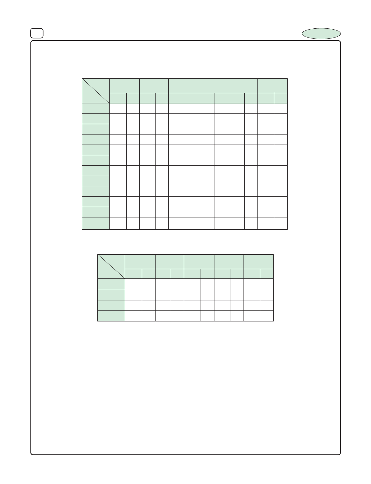
42 ALUMINIUM ELECTROLYTIC CAPACITORS
12. DIMENSIONS Vs PERMISSIBLE RIPPLE CURRENT :
Dimensions : D x L (mm) Ripple Current (IA) : mA/rms at 120 Hz 850C
INCAP
µF
10000
15000
22000
33000
W.V .
1000
1500
2000
2200
2500
4700
5000
6800
25
I
DxL
30x50 2.1 30x50 3.2 30x50 3.5 35x68 4.1
30x50 2.7 30x50 3.5 30x50 4.2 35x68 4.7 45x68 6.8
35x52 3.7 35x52 4.1 30x50 4.5 35x52 4.8 35x68 5.6
35x68 4.5 35x68 5.4 35x68 6.0 40x68 6.9
35x68 5.3 40x68 6.3
W.V .
35
I
DxL
A
30x40 2.5 30x50 2.75 35x68 4.0
160
A
200
DxL
40
50
I
A
I
DxL
30x50 2.0 30x50 2.2
30x50 2.1 30x50 2.2
250
63
I
DxL
A
35x52 3.73 40x68 4.8
350
A
450
DxL
30x40 1.2
100
I
A
µF
470
1000
1500
2200
DxL
35x68 2.1 35x68 2.5 40x68 2.2 40x68 4.8
35x68 2.75 35x68 2.6
40x68 3.75 40x68 4.1
Note : For non std. Sizes contact factory.
LT2 series (1050C) Contact factory for specification
DxL
I
DxL
A
I
A
I
A
DxL
I
A
I
DxL
35x68 2.6
A
Page 45
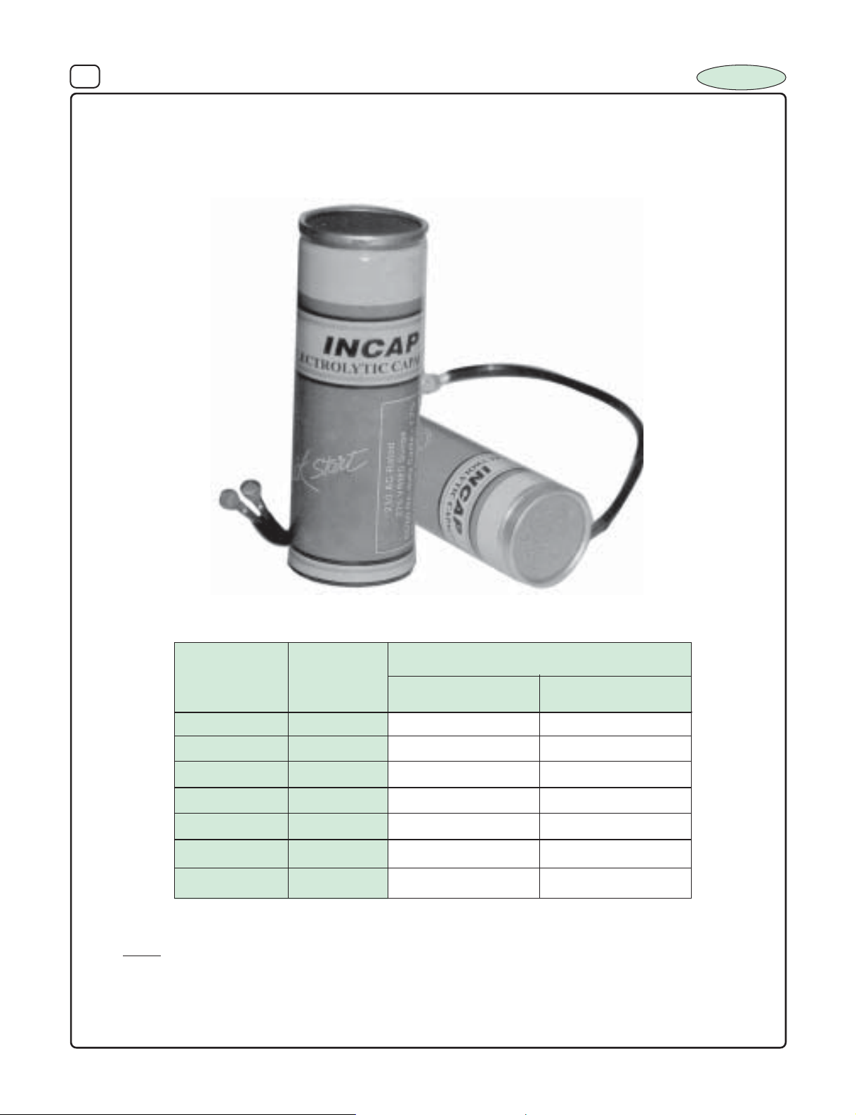
43 ALUMINIUM ELECTROLYTIC CAPACITORS
230V AC MOTOR START CAPACITORS
INCAP
As per IS 2993
Motor Rating
HP
1/4 40/60 40x90 35x52
1/3 60/80 40x90 35x52
1/2 80/100 40x90 35x52
3/4 100/120 40x110 35x68
1 120/150 40x110 35x68
1
1
/
4
1
/
– 2 200/250 45x130 40x86
1
4
Mfd
150/200 45x130 40x86
MS 1 Series
(Duble Can)
Case Size
MS 2 Series
(Single Can)
NOTE : Contact Factory for 110V AC single can and double can motor start capacitors
Compact size Rugged Bakelite Body Capacitors with dual quick connect
terminals can be supplied as import substitute. Voltage ranges 110 V AC - 250 V AC
Page 46
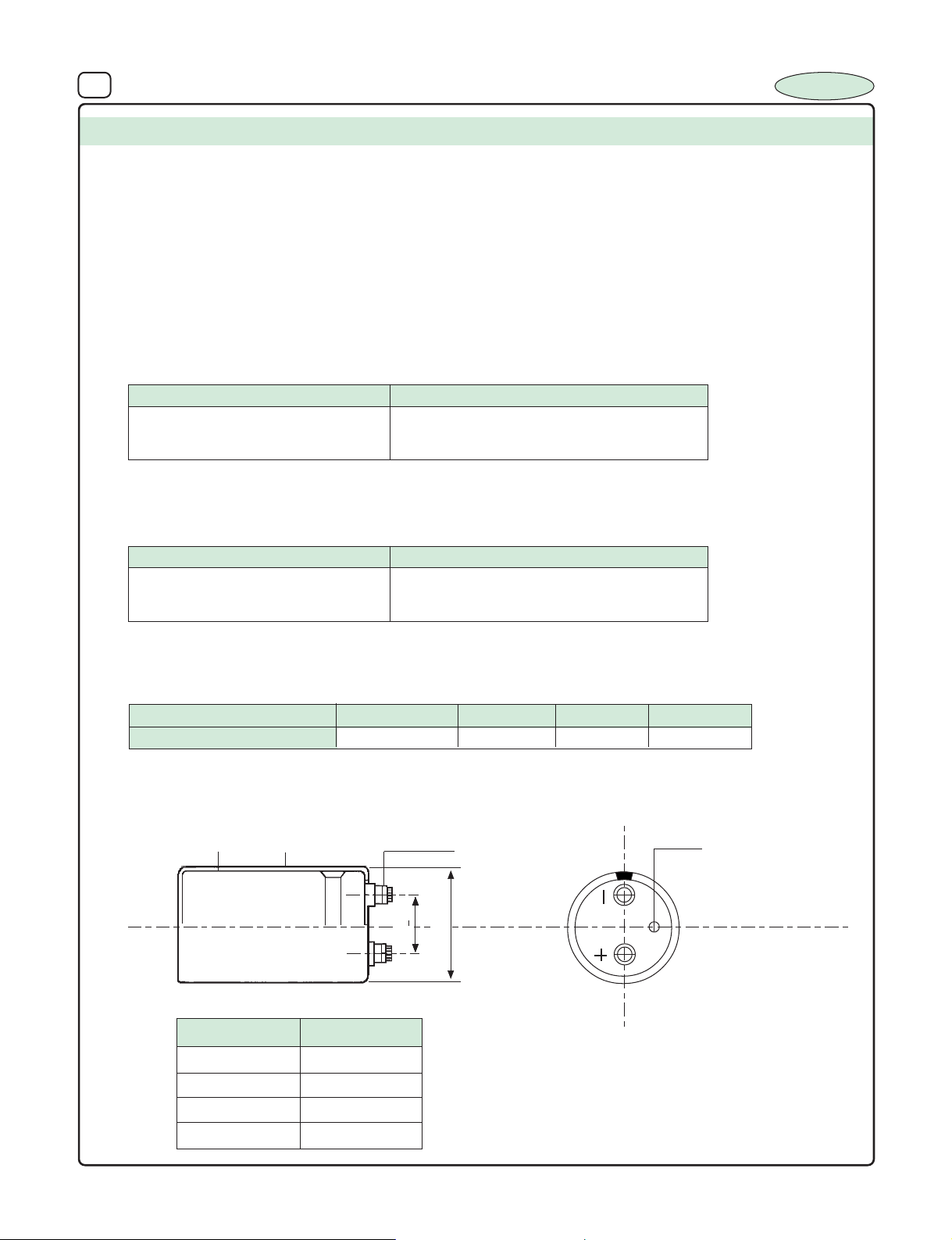
44 ALUMINIUM ELECTROLYTIC CAPACITORS
SERIES : ST 1 - G
TYPE : Screw Terminal
FEATURES : 850C, Professional Grade
SPECIFICATION TABLE :
1. OPERATING TEMPERATURE RANGE : – 400 C to 850C –250C to +850C
2. VOLTAGE RANGE : 16V to 100 VDC 160V to 450VDC
3. CAPACITANCE RANGE : 2200 µF to 100000 µF 1000-10000 µF
4. CAPACITANCE TOLERANCE at 250C, 120 Hz : +_ 20%
5. LEAKAGE CURRENT (I) : 0.06CV+200µA or 5mA which ever is smaller
(Charging at rated voltage for 5min.)
6. LOAD LIFE TEST :
Test Time 1000 Hrs
Capacitance Change +_ 20% of the initial masured Value
Dissipation Factor Less than 200% of Specified Value
Leakage Current Within specified Value
I : Leakage Current (µA) C : Rated Capacitance (µF) V : Rated V oltage (V)
INCAP
The Capacitor after load life test for 1000 hrs. at 85
Note : A recovery time of 16 hrs. should be given before taking the measur ments after load life test.
7. SHELF TEST :
Test Time
Capacitance Change +_ 20% of the initial mesured value
Dissipation Factor Less than 200% of Specified Value
Leakage Current Within specified Value
The Capacitor after shelf test for 500 hrs. at 85
Note : A recovery time of 16 hrs. should be given before taking the measur ments after shelf test.
8. RIPPLE CURRENT & TEMPERATURE MULTIPLIERS :
Temperature (0C)
Multiplier
9. MARKING :
Brand name, Capacitance Value, Working Voltage, Polarity marking, Operating Temperature and month of manufacture.
10. DIAGRAM DIMENSIONS :
Bottom Plate
Sleeve (PVC)
0
C should meet the above specification
500 Hrs
0
C should meet the above specification
Below 40
1.8 1
M5 Full Thread
60
1.4
70
1.2
85
Safety Vent
Dimension of terminal pitch (W)
•
φDW
35 13
50 22.0
63.6 28.6
76 32
W + 1
D + 2 MAX
Page 47
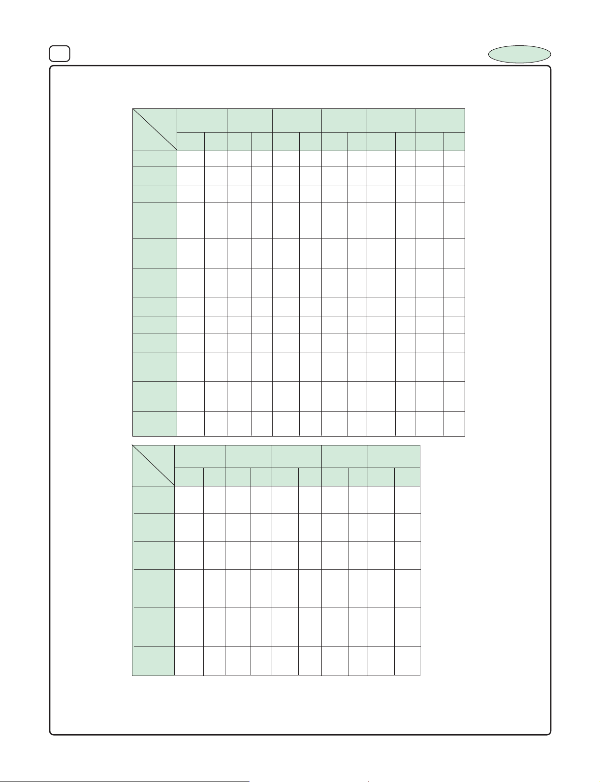
45 ALUMINIUM ELECTROLYTIC CAPACITORS
11. DIMENSIONS Vs PERMISSIBLE RIPPLE CURRENT :
Dimensions : D x L (mm) Ripple Current (IA) : A/rms at 120 Hz 850C
INCAP
µF
2200
2500
4700
5000
6800
10000
15000
20000
22000
25000
33000
47000
W.V .
16
I
DxL
35x62 4.0 35x62 4.5 35x62 5.5 35x68 5.6 35x80 6.5 50x80 8.5
35x62 4.58 35x62 5.3 35x80 7.0 35x80 8.5 50x80 9.6
35x62 5.3 35x68 5.35 50x68 9.5 50x80 10.2
35x62 6.14 50x68 8.2 50x80 11.8
35x80 6.14
35x68 6.6 50x80 9.35 50x80 13.2
50x80 6.6
25
I
DxL
A
35x62 3.5 35x62 3.8 35x62 3.9 35x62 4.5 50x80 5.6
35x62 3.9 35x62 4.2 35x62 4.5 35x62 5.7 50x80 7.2
40
DxL
A
35x62 2.65 35x62 3.05 35x62 3.35
50x68 7.5 50x80 9.4
I
50
I
DxL
A
35x62 4.0 35x62 4.65 50x80 5.8
50x80 9.8 50x80 10.0
50x80 10.5
A
DxL
63
I
A
100
I
DxL
35x62 3.2
50x105 9.2
A
100000
µF
10000
50x80 13.7 50x80 14.5 76x145 15.5
W.V .
1000
1500
2200
3300
4700
160
DxL
35x80 3.4 35x80 3.50 50x80 3.55 50x80 3.8 50x105 4.0
50x80 3.8
35x80 4.0 35x80 4.1
50x80 5.0
50x80 4.1 50x80 4.3 50x80 4.5 63x145 6.0 63x96 6.6
50x80 6.2 50x80 6.5 63x120 7.1 63x96 7.3 76x105 7.9
63x96 10.3 63x96 10.8 63x130 11.6
200
I
DxL
A
63x105 7.0 63x120 7.45 76x145 8.15
63x120 9.0 63x145 9.2 76x105 9.3 76x130 10.0
76x145 13.8 76x145 14.9
250
I
DxL
A
63x105 6.2 63x120 6.8
350
I
DxL
A
76x105 8.0
76x120 9.3 76x145 10.2
76x145 9.8
450
I
A
DxL
I
A
Following Capacitors can be supplied
1) Equivalent to foreign substitute such as ITELCOND, KENDEIL, EPCOS etc.,
2) Capacitors with higher ripple for specific application
0
3) 105
C 2000 hrs category especially for Railway Applications.
Page 48
46 ALUMINIUM ELECTROLYTIC CAPACITORS
NOTES
INCAP
Page 49
49 ALUMINIUM ELECTROLYTIC CAPACITORS
NOTES
INCAP
Page 50
48 ALUMINIUM ELECTROLYTIC CAPACITORS
NOTES
INCAP
Page 51
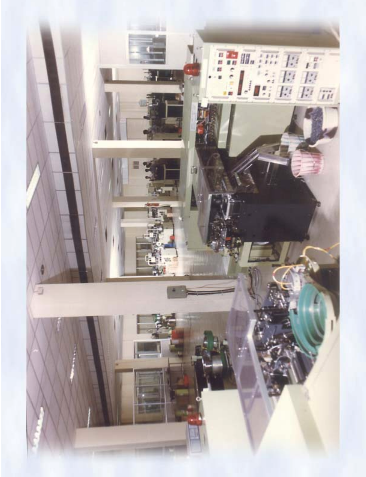
Page 52
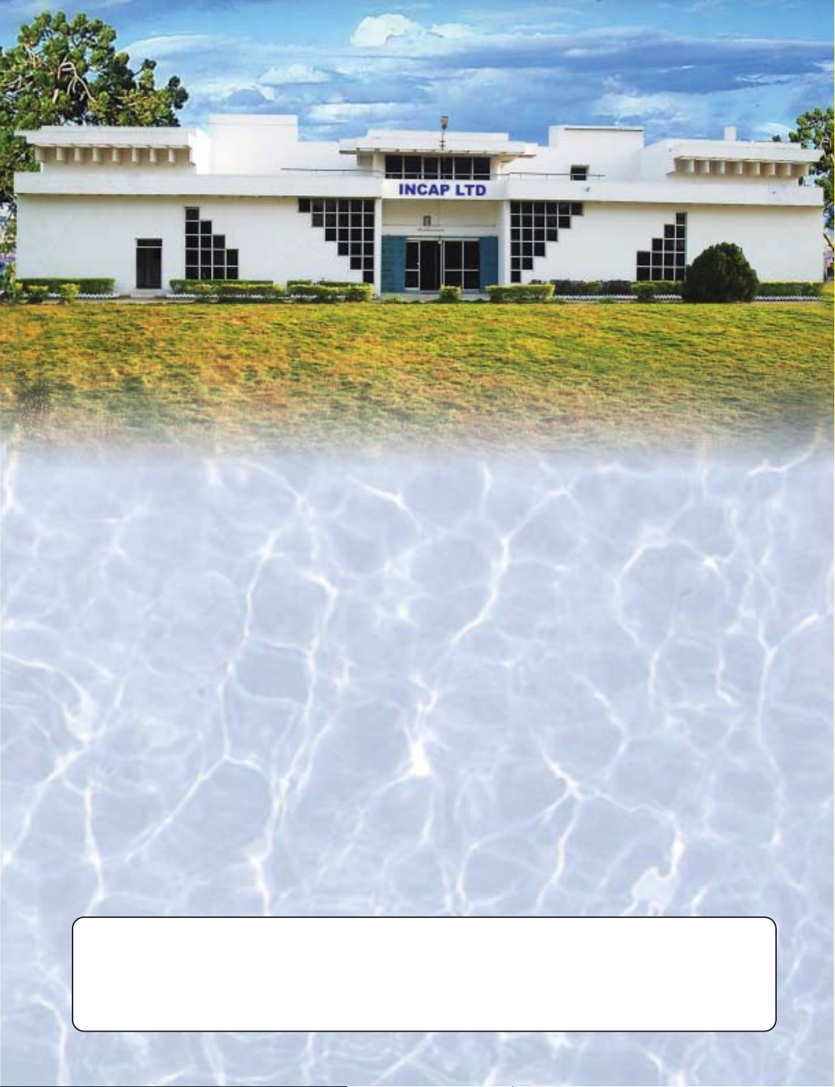
REGD. & ADMN. OFFICE
INCAP LIMITED
1-58, Nidamanur, VIJAYAWADA - 521 104
Phone : 91-0866-2842479, 2842571, 2841147 Fax : 91-0866-2842572
Email : [email protected] URL : www.incapltd.com
DELHI OFFICE :
Mr. ANUPAM MISHRA
H.No. 312, Block - B - 1, Aravali Apartments, Sector - 34,
Gautam Budh Nagar, NOIDA - 201303 (U.P.).
Phone : 0120-24507620
Mobile : 09313205406
Email : [email protected]
MUMBAI OFFICE :
Mr. V. SOMASUNDARAM IYER
Shree Laxmi Part II, Building No. 4/ 'A' Wing,
Flat No. 704, Pada No. 2, Lokmanya Nagar, THANE - 400 606
Phone : 25884500
Mobile : 09324516755
Email : [email protected]
[email protected]
CHENNAI OFFICE :
Mr. R. RAVICHANDRAN
Plot No. 34, Dr. No. 6/14 Street,
Tansi Nagar Extn., Velachery,
CHENNAI - 600 042
Phone : 2475540, 2432021
Mobile : 09382624155
Email : [email protected]
 Loading...