

Page 1
®
INA114
INA114
Precision
INSTRUMENTATION AMPLIFIER
INA114
FEATURES
● LOW OFFSET VOLTAGE: 50µV max
● LOW DRIFT: 0.25
µV/°C max
● LOW INPUT BIAS CURRENT: 2nA max
● HIGH COMMON-MODE REJECTION:
115dB min
● INPUT OVER-VOLTAGE PROTECTION:
±40V
● WIDE SUPPLY RANGE:
● LOW QUIESCENT CURRENT: 3mA max
● 8-PIN PLASTIC AND SOL-16
±2.25 to ±18V
APPLICATIONS
● BRIDGE AMPLIFIER
● THERMOCOUPLE AMPLIFIER
● RTD SENSOR AMPLIFIER
● MEDICAL INSTRUMENTATION
● DATA ACQUISITION
DESCRIPTION
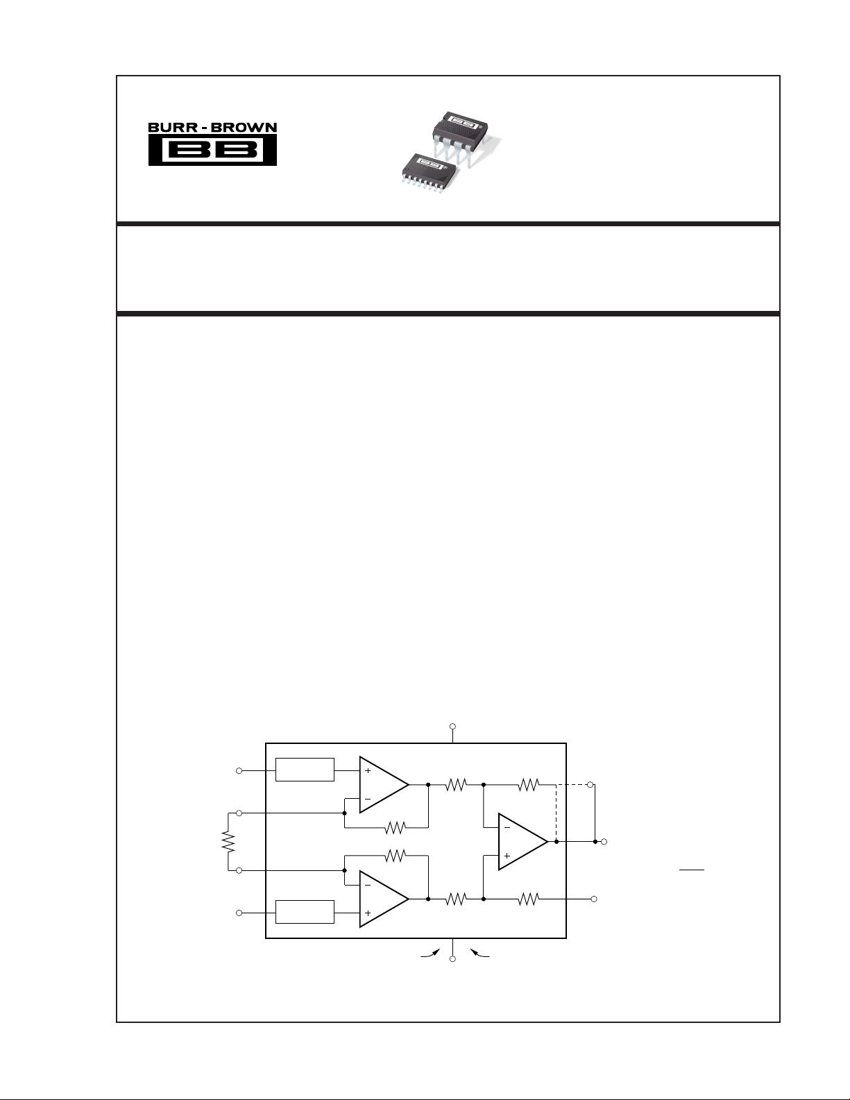
The INA114 is a low cost, general purpose instrumentation amplifier offering excellent accuracy. Its versatile 3-op amp design and small size make it ideal for a
wide range of applications.
A single external resistor sets any gain from 1 to 10,000.
Internal input protection can withstand up to ±40V
without damage.
The INA114 is laser trimmed for very low offset voltage
(50µV), drift (0.25µV/°C) and high common-mode
rejection (115dB at G = 1000). It operates with power
supplies as low as ±2.25V, allowing use in battery
operated and single 5V supply systems. Quiescent current is 3mA maximum.
The INA114 is available in 8-pin plastic and SOL-16
surface-mount packages. Both are specified for the
–40°C to +85°C temperature range.
V+
(13)7
SBOS014
–
2
R
(4)
(2)
G
(15)
(5)
1
8
3
Over-Voltage
Protection
Over-Voltage
Protection
A
1
25kΩ
25kΩ
A
2
DIP (SOIC)
V
IN
+
V
IN
International Airport Industrial Park • Mailing Address: PO Box 11400, Tucson, AZ 85734 • Street Address: 6730 S. Tucson Blvd., Tucson, AZ 85706 • Tel: (520) 746-1111 • Twx: 910-952-1111
Internet: http://www.burr-brown.com/ • FAXLine: (800) 548-6133 (US/Canada Only) • Cable: BBRCORP • Telex: 066-6491 • FAX: (520) 889-1510 • Immediate Product Info: (800) 548-6132
©1992 Burr-Brown Corporation PDS-1142D Printed in U.S.A. March, 1998
INA114
25kΩ25kΩ
A
3
25kΩ25kΩ
(7)4
V–
1
Feedback
(12)
6
(11)
5
(10)
DIP Connected
Internally
V
O
G = 1 +
Ref
INA114
50kΩ
R
G
®
Page 2
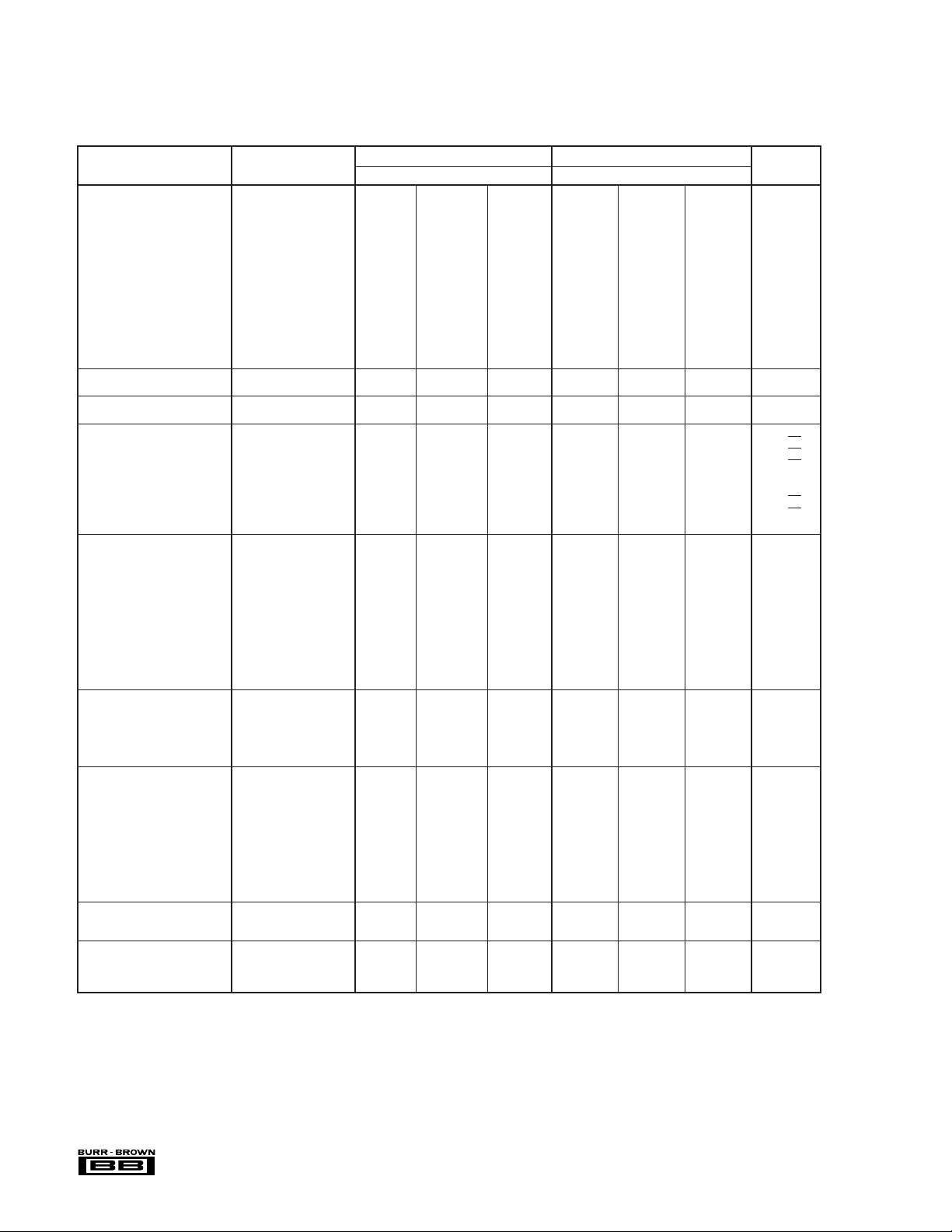
SPECIFICATIONS
ELECTRICAL
At TA = +25°C, VS = ±15V, RL = 2kΩ, unless otherwise noted.
INA114BP, BU INA114AP, AU
PARAMETER CONDITIONS MIN TYP MAX MIN TYP MAX UNITS
INPUT
Offset Voltage, RTI
Initial T
vs Temperature T
vs Power Supply V
Long-Term Stability ±0.2 + 0.5/G ✻ µV/mo
Impedance, Differential 10
Common-Mode 10
Input Common-Mode Range ±11 ±13.5 ✻✻ V
Safe Input Voltage ±40 ✻ V
Common-Mode Rejection V
BIAS CURRENT ±0.5 ±2 ✻ ±5nA
vs Temperature ±8 ✻ pA/°C
OFFSET CURRENT ±0.5 ±2 ✻ ±5nA
vs Temperature ±8 ✻ pA/°C
NOISE VOLTAGE, RTI G = 1000, R
f = 10Hz 15 ✻ nV/√Hz
f = 100Hz 11 ✻ nV/√Hz
f = 1kHz 11 ✻ nV/√Hz
= 0.1Hz to 10Hz 0.4 ✻ µVp-p
f
B
Noise Current
f=10Hz 0.4 ✻ pA/√Hz
f=1kHz 0.2 ✻ pA/√Hz
= 0.1Hz to 10Hz 18 ✻ pAp-p
f
B
GAIN
Gain Equation 1 + (50kΩ/R
Range of Gain 1 10000 ✻✻V/V
Gain Error G = 1 ±0.01 ±0.05 ✻✻%
Gain vs Temperature G = 1 ±2 ±10 ✻ ±10 ppm/°C
50kΩ Resistance
Nonlinearity G = 1 ±0.0001 ±0.001 ✻ ±0.002 % of FSR
OUTPUT
Voltage I
Load Capacitance Stability 1000 ✻ pF
Short Circuit Current +20/–15 ✻ mA
FREQUENCY RESPONSE
Bandwidth, –3dB G = 1 1 ✻ MHz
Slew Rate V
Settling Time, 0.01% G = 1 18 ✻ µs
(1)
Overload Recovery 50% Overdrive 20 ✻ µs
POWER SUPPLY
Voltage Range ±2.25 ±15 ±18 ✻✻ ✻V
Current V
TEMPERATURE RANGE
Specification –40 85 ✻✻°C
Operating –40 125 ✻✻°C
θ
JA
✻ Specification same as INA114BP/BU.
NOTE: (1) Temperature coefficient of the “50kΩ” term in the gain equation.
= +25°C ±10 + 20/G ±50 + 100/G ±25 + 30/G ±125 + 500/G µV
A
= T
to T
A
MIN
= ±2.25V to ±18V 0.5 + 2/G 3 + 10/G ✻✻µV/V
S
= ±10V, ∆RS = 1kΩ
CM
MAX
G = 1 80 96 75 90 dB
G = 10 96 115 90 106 dB
G = 100 110 120 106 110 dB
G = 1000 115 120 106 110 dB
= 0Ω
S
G = 10 ±0.02 ±0.4 ✻ ±0.5 %
G = 100 ±0.05 ±0.5 ✻ ±0.7 %
G = 1000 ±0.5 ±1 ✻ ±2%
±0.1 + 0.5/G ±0.25 + 5/G ±0.25 + 5/G ±1 + 10/G µV/°C
10
|| 6 ✻ Ω || pF
10
|| 6 ✻ Ω || pF
) ✻ V/V
G
±25 ±100 ✻✻ppm/°C
G = 10 ±0.0005 ±0.002 ✻ ±0.004 % of FSR
G = 100 ±0.0005 ±0.002 ✻ ±0.004 % of FSR
G = 1000 ±0.002 ±0.01 ✻ ±0.02 % of FSR
= 5mA, T
O
= ±11.4V, RL = 2kΩ±10 ±10.5 ✻✻ V
V
S
= ±2.25V, RL = 2kΩ±1 ±1.5 ✻✻ V
V
S
O
to T
MIN
G = 10 100 ✻ kHz
G = 100 10 ✻ kHz
G = 1000 1 ✻ kHz
= ±10V, G = 10 0.3 0.6 ✻✻ V/µs
G = 10 20 ✻ µs
G = 100 120 ✻ µs
G = 1000 1100 ✻ µs
= 0V ±2.2 ±3 ✻✻mA
IN
±13.5 ±13.7 ✻✻ V
MAX
80 ✻ °C/W
The information provided herein is believed to be reliable; however, BURR-BROWN assumes no responsibility for inaccuracies or omissions. BURR-BROWN assumes
no responsibility for the use of this information, and all use of such information shall be entirely at the user’s own risk. Prices and specifications are subject to change
without notice. No patent rights or licenses to any of the circuits described herein are implied or granted to any third party. BURR-BROWN does not authorize or warrant
any BURR-BROWN product for use in life support devices and/or systems.
®
INA114
2
Page 3
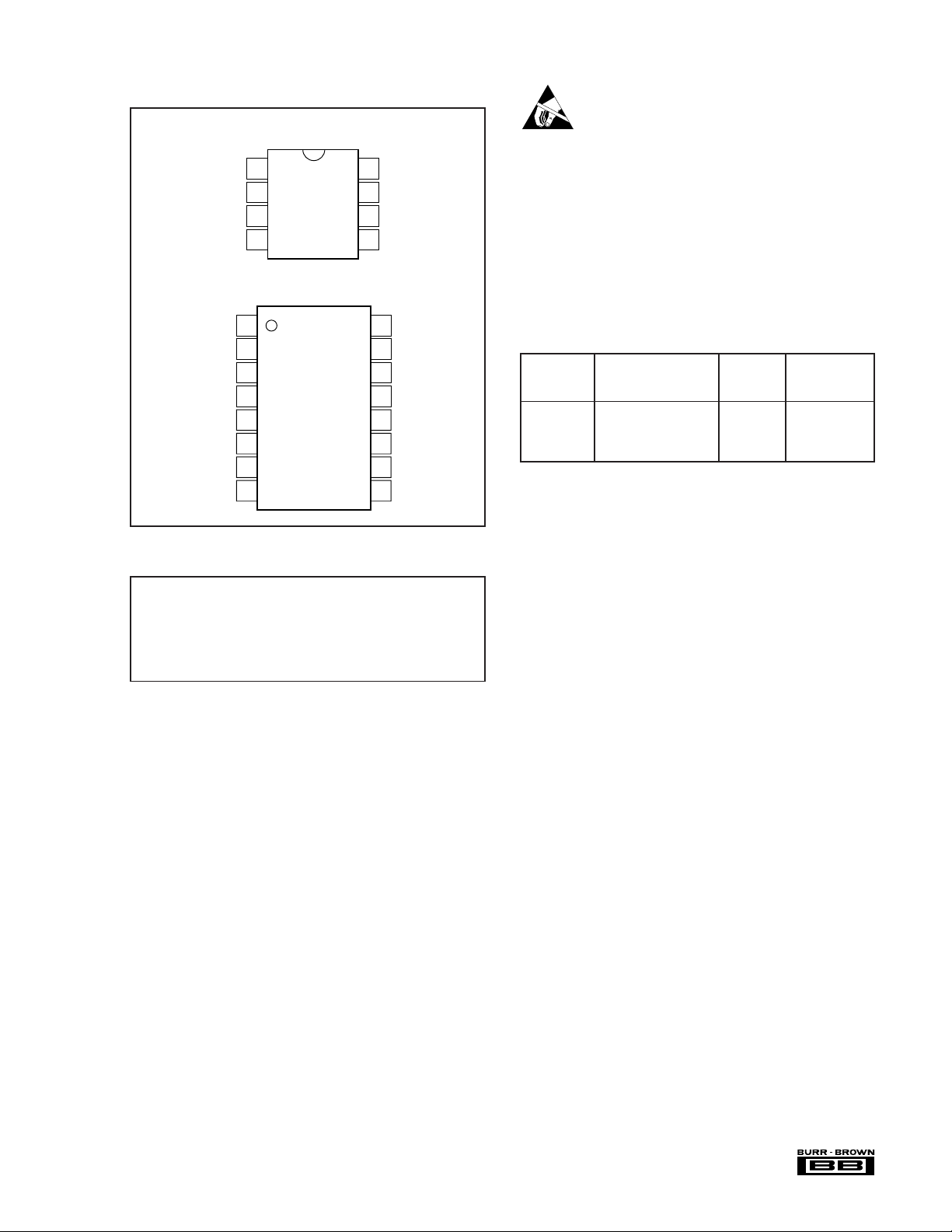
PIN CONFIGURATIONS
ELECTROSTATIC
P Package 8-Pin DIP
R
G
–
V
IN
+
V
IN
V–
U Package SOL-16 Surface-Mount
1
NC
2
R
G
3
NC
–
4
V
IN
+
5
V
IN
6
NC
7
V–
8
NC
Top View
1
2
3
4
Top View
ABSOLUTE MAXIMUM RATINGS
(1)
8
7
6
5
R
V+
V
Ref
16
15
14
13
12
11
10
9
G
O
NC
R
G
NC
V+
Feedback
V
O
Ref
NC
DISCHARGE SENSITIVITY
This integrated circuit can be damaged by ESD. Burr-Brown
recommends that all integrated circuits be handled with appropriate precautions. Failure to observe proper handling and
installation procedures can cause damage.
ESD damage can range from subtle performance degradation
to complete device failure. Precision integrated circuits may
be more susceptible to damage because very small parametric
changes could cause the device not to meet its published
specifications.
PACKAGE/ORDERING INFORMATION
PACKAGE
DRAWING TEMPERATURE
PRODUCT PACKAGE NUMBER
INA114AP 8-Pin Plastic DIP 006 –40°C to +85°C
INA114BP 8-Pin Plastic DIP 006 –40°C to +85°C
INA114AU SOL-16 Surface-Mount 211 –40°C to +85°C
INA114BU SOL-16 Surface-Mount 211 –40°C to +85°C
NOTE: (1) For detailed drawing and dimension table, please see end of data
sheet, or Appendix C of Burr-Brown IC Data Book.
(1)
RANGE
Supply Voltage .................................................................................. ±18V
Input Voltage Range .......................................................................... ±40V
Output Short-Circuit (to ground) .............................................. Continuous
Operating Temperature ................................................. –40°C to +125°C
Storage Temperature ..................................................... –40°C to +125°C
Junction Temperature.................................................................... +150°C
Lead Temperature (soldering, 10s)............................................... +300°C
NOTE: (1) Stresses above these ratings may cause permanent damage.
®
3
INA114
Page 4
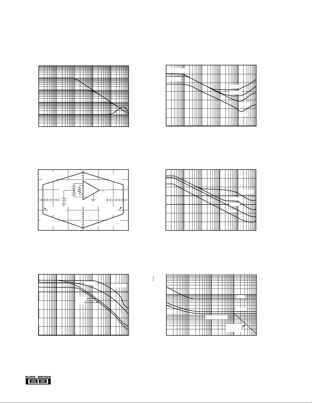
TYPICAL PERFORMANCE CURVES
At TA = +25°C, VS = ±15V, unless otherwise noted.
1k
100
10
Gain (V/V)
1
10 100 10k 100k 1M1k
INPUT COMMON-MODE VOLTAGE RANGE
15
10
5
Limited by A
+ Output Swing
1
V
V
0
–5
Common-Mode Voltage (V)
–10
A3 – Output
Swing Limit
Limited by A
– Output Swing
2
–15
–15 –10 0 5 15–5
GAIN vs FREQUENCY
Frequency (Hz)
vs OUTPUT VOLTAGE
–
D/2
+
–
D/2
+
V
CM
(Any Gain)
Output Voltage (V)
Limited by A
+ Output Swing
V
O
A3 + Output
Swing Limit
1
Limited by A
– Output Swing
10
140
COMMON-MODE REJECTION vs FREQUENCY
G = 100, 1k
120
G = 10
100
80
G = 1k
G = 100
60
G = 10
40
Common-Mode Rejection (dB)
20
G = 1
0
10 100 10k 100k 1M1k
Frequency (Hz)
POSITIVE POWER SUPPLY REJECTION
140
2
120
vs FREQUENCY
100
80
60
40
Power Supply Rejection (dB)
20
G = 1000
G = 100
G = 10
G = 1
0
10 100 10k 1M1k
100k
Frequency (Hz)
NEGATIVE POWER SUPPLY REJECTION
140
120
100
80
60
40
Power Supply Rejection (dB)
20
0
10 100 10k 1M1k
®
INA114
vs FREQUENCY
G = 100
G = 10
G = 1
Frequency (Hz)
G = 1000
100k
INPUT-REFERRED NOISE VOLTAGE
1k
100
vs FREQUENCY
G = 1
G = 10
10
G = 100, 1000
G = 1000
Input-Referred Noise Voltage (nV/√ Hz)
1
110 1k100
BW Limit
10k
Frequency (Hz)
4
Page 5
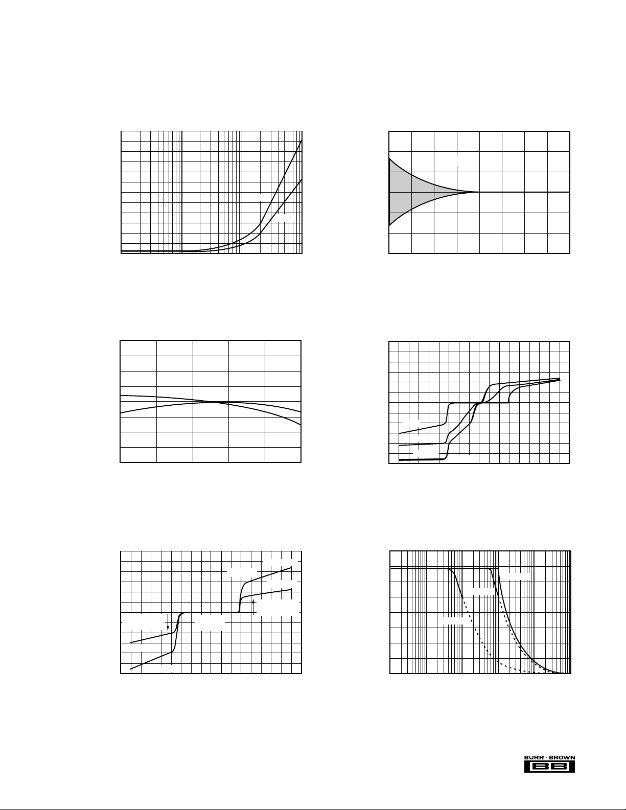
MAXIMUM OUTPUT SWING vs FREQUENCY
Peak-to-Peak Amplitude (V)
10
32
28
24
20
16
12
8
4
0
100 10k 1M
Frequency (Hz)
100k1k
G = 100
G = 1, 10
G = 1000
INPUT BIAS CURRENT
vs DIFFERENTIAL INPUT VOLTAGE
Differential Overload Voltage (V)
Input Bias Current (mA)
–45
3
2
1
0
–1
–2
–3
–30 –15 0 15 30 45
G = 1
G = 10
G = 1000
G = 100
TYPICAL PERFORMANCE CURVES (CONT)
At TA = +25°C, VS = ±15V, unless otherwise noted.
1200
1000
800
600
400
Settling Time (µs)
200
0
1 100 100010
INPUT BIAS AND INPUT OFFSET CURRENT
2
1
±I
B
0
I
SETTLING TIME vs GAIN
vs TEMPERATURE
OS
Gain (V/V)
0.01%
0.1%
6
4
2
0
–2
Offset Voltage Change (µV)
–4
–6
OFFSET VOLTAGE WARM-UP vs TIME
0
15 30 45 60 75 90 105 120
Time from Power Supply Turn-on (s)
G ≥ 100
–1
Input Bias and Input Offset Current (nA)
–2
–40
3
2
1
0
–1
Input Bias Current (mA)
–2
–3
–45
–15 10 35 60 85
INPUT BIAS CURRENT
vs COMMON-MODE INPUT VOLTAGE
Over-Voltage
Protection
One Input
Both Inputs
–30 –15 0 15 30 45
Common-Mode Voltage (V)
Temperature (°C)
|Ib1| + |Ib2|
Normal
Operation
Both Inputs
One Input
Over-Voltage
Protection
®
5
INA114
Page 6
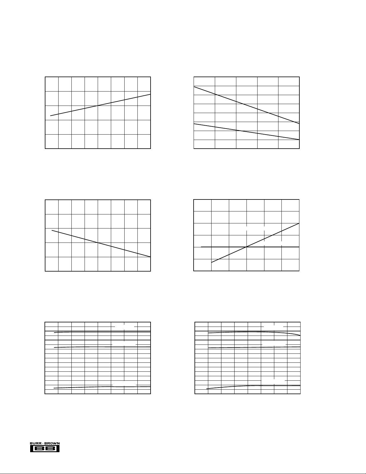
TYPICAL PERFORMANCE CURVES (CONT)
At TA = +25°C, VS = ±15V, unless otherwise noted.
1.0
0.8
0.6
0.4
Slew Rate (V/µs)
0.2
0
–75
2.8
2.6
2.4
2.2
Quiescent Current (mA)
2.0
SLEW RATE vs TEMPERATURE
–50 –25 0 25 50 75 100
QUIESCENT CURRENT vs TEMPERATURE
Temperature (°C)
125
OUTPUT CURRENT LIMIT vs TEMPERATURE
30
25
20
15
Short Circuit Current (mA)
10
–40
2.6
2.5
2.4
2.3
2.2
Quiescent Current (mA)
2.1
–15 10 35 60
Temperature (°C)
QUIESCENT CURRENT AND POWER DISSIPATION
vs POWER SUPPLY VOLTAGE
Power Dissipation
+|I
|
CL
–|I
Quiescent Current
|
CL
85
120
100
80
60
40
Power Dissipation (mW)
20
1.8
–75
–50 –25 0 25 50 75 100
Temperature (°C)
POSITIVE SIGNAL SWING vs TEMPERATUE (RL = 2kΩ)
16
14
12
10
8
6
Output Voltage (V)
4
2
0
–75
–50 –25 0 25 50 75 100
®
Temperature (°C)
VS = ±15V
VS = ±11.4V
VS = ±2.25V
INA114
125
125
2.0
–16
–14
–12
–10
–8
–6
Output Voltage (V)
–4
–2
6
0
±3 ±6 ±9 ±12 ±15 ±18
Power Supply Voltage (V)
NEGATIVE SIGNAL SWING vs TEMPERATUE (RL = 2kΩ)
VS = ±15V
VS = ±11.4V
VS = ±2.25V
0
–75
–50 –25 0 25 50 75 100
Temperature (°C)
0
125
Page 7
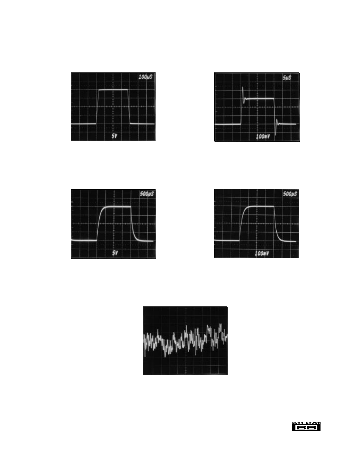
TYPICAL PERFORMANCE CURVES (CONT)
At TA = +25°C, VS = ±15V, unless otherwise noted.
LARGE SIGNAL RESPONSE, G = 1 SMALL SIGNAL RESPONSE, G = 1
+10V
0
+100mV
0
–10V
LARGE SIGNAL RESPONSE, G = 1000 SMALL SIGNAL RESPONSE, G = 1000
+10V
0
–10V
–200mV
+200mV
0
–200mV
INPUT-REFERRED NOISE, 0.1 to 10Hz
1 s/div
7
0.1µV/div
®
INA114
Page 8
APPLICATION INFORMATION
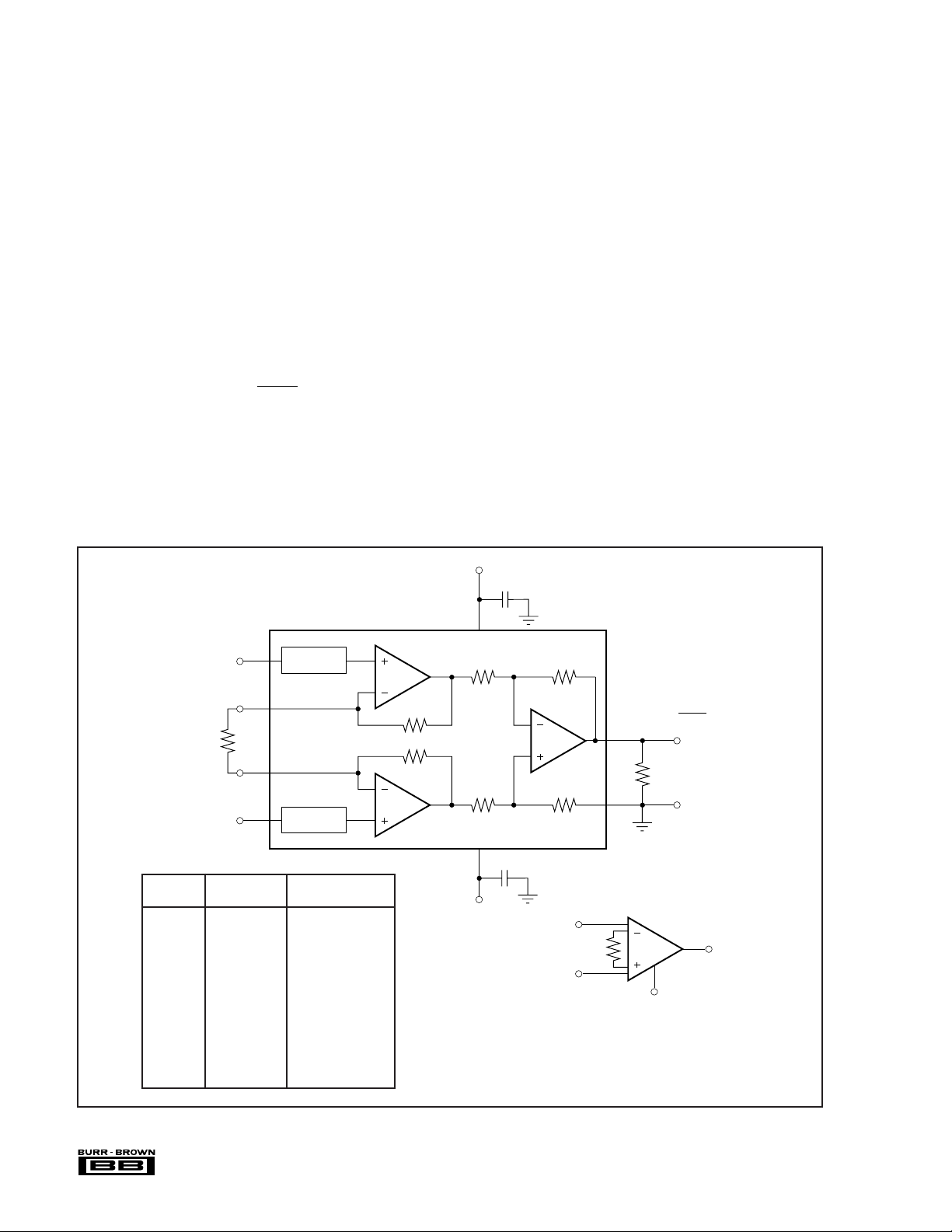
Figure 1 shows the basic connections required for operation
of the INA114. Applications with noisy or high impedance
power supplies may require decoupling capacitors close to
the device pins as shown.
The output is referred to the output reference (Ref) terminal
which is normally grounded. This must be a low-impedance
connection to assure good common-mode rejection. A resistance of 5Ω in series with the Ref pin will cause a typical
device to degrade to approximately 80dB CMR (G = 1).
SETTING THE GAIN
Gain of the INA114 is set by connecting a single external
resistor, R
:
G
G = 1 +
50 kΩ
R
G
(1)
Commonly used gains and resistor values are shown in
Figure 1.
The 50kΩ term in equation (1) comes from the sum of the
two internal feedback resistors. These are on-chip metal film
resistors which are laser trimmed to accurate absolute val-
Pin numbers are
for DIP packages.
ues. The accuracy and temperature coefficient of these
resistors are included in the gain accuracy and drift specifications of the INA114.
The stability and temperature drift of the external gain
setting resistor, R
, also affects gain. RG’s contribution to
G
gain accuracy and drift can be directly inferred from the gain
equation (1). Low resistor values required for high gain can
make wiring resistance important. Sockets add to the wiring
resistance which will contribute additional gain error (possibly an unstable gain error) in gains of approximately 100 or
greater.
NOISE PERFORMANCE
The INA114 provides very low noise in most applications.
For differential source impedances less than 1kΩ, the INA103
may provide lower noise. For source impedances greater
than 50kΩ, the INA111 FET-input instrumentation amplifier may provide lower noise.
Low frequency noise of the INA114 is approximately
0.4µVp-p measured from 0.1 to 10Hz. This is approximately
one-tenth the noise of “low noise” chopper-stabilized amplifiers.
V+
0.1µF
7
–
2
G
G
1
8
3
Over-Voltage
Over-Voltage
Protection
Protection
NEAREST 1% R
A
1
25kΩ
25kΩ
A
2
G
V
IN
R
+
V
IN
DESIRED R
GAIN (Ω)(Ω)
1 No Connection No Connection
2 50.00k 49.9k
5 12.50k 12.4k
10 5.556k 5.62k
20 2.632k 2.61k
50 1.02k 1.02k
100 505.1 511
200 251.3 249
500 100.2 100
1000 50.05 49.9
2000 25.01 24.9
5000 10.00 10
10000 5.001 4.99
INA114
+
50kΩ
R
+
V
–
–
G
O
V
O
= G • (VIN – VIN)
V
25kΩ25kΩ
A
3
25kΩ25kΩ
4
0.1µF
V–
Also drawn in simplified form:
–
V
IN
R
+
V
IN
O
G = 1 +
6
Load
5
INA114
G
Ref
FIGURE 1. Basic Connections.
®
INA114
8
Page 9
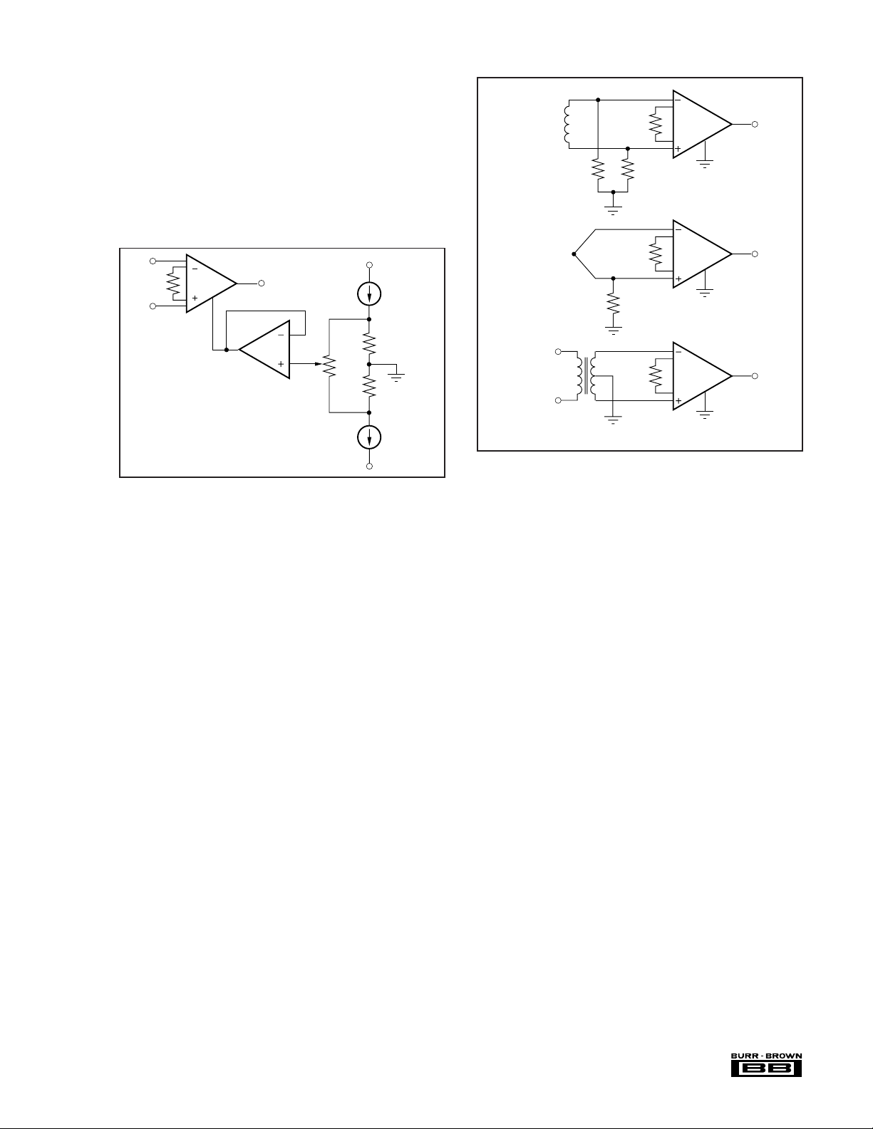
OFFSET TRIMMING
The INA114 is laser trimmed for very low offset voltage and
drift. Most applications require no external offset adjustment. Figure 2 shows an optional circuit for trimming the
output offset voltage. The voltage applied to Ref terminal is
summed at the output. Low impedance must be maintained
at this node to assure good common-mode rejection. This is
achieved by buffering trim voltage with an op amp as
shown.
Microphone,
Hydrophone
etc.
INA114
47kΩ47kΩ
–
V
IN
INA114
R
G
+
V
IN
±10mV
Adjustment Range
Ref
V
O
OPA177
V+
100µA
1/2 REF200
100Ω
10kΩ
100Ω
100µA
1/2 REF200
V–
FIGURE 2. Optional Trimming of Output Offset Voltage.
INPUT BIAS CURRENT RETURN PATH
The input impedance of the INA114 is extremely high—
10
approximately 10
Ω. However, a path must be provided for
the input bias current of both inputs. This input bias current
is typically less than ±1nA (it can be either polarity due to
cancellation circuitry). High input impedance means that
this input bias current changes very little with varying input
voltage.
Input circuitry must provide a path for this input bias current
if the INA114 is to operate properly. Figure 3 shows various
provisions for an input bias current path. Without a bias
current return path, the inputs will float to a potential which
exceeds the common-mode range of the INA114 and the
input amplifiers will saturate. If the differential source resistance is low, bias current return path can be connected to one
input (see thermocouple example in Figure 3). With higher
source impedance, using two resistors provides a balanced
input with possible advantages of lower input offset voltage
due to bias current and better common-mode rejection.
INPUT COMMON-MODE RANGE
The linear common-mode range of the input op amps of the
INA114 is approximately ±13.75V (or 1.25V from the
power supplies). As the output voltage increases, however,
the linear input range will be limited by the output voltage
swing of the input amplifiers, A
and A2. The common-
1
mode range is related to the output voltage of the complete
amplifier—see performance curve “Input Common-Mode
Range vs Output Voltage.”
Thermocouple
10kΩ
Center-tap provides
bias current return.
INA114
INA114
FIGURE 3. Providing an Input Common-Mode Current Path.
A combination of common-mode and differential input
signals can cause the output of A
4 shows the output voltage swing of A
or A2 to saturate. Figure
1
and A2 expressed in
1
terms of a common-mode and differential input voltages.
Output swing capability of these internal amplifiers is the
same as the output amplifier, A
. For applications where
3
input common-mode range must be maximized, limit the
output voltage swing by connecting the INA114 in a lower
gain (see performance curve “Input Common-Mode Voltage
Range vs Output Voltage”). If necessary, add gain after the
INA114 to increase the voltage swing.
Input-overload often produces an output voltage that appears
normal. For example, an input voltage of +20V on one input
and +40V on the other input will obviously exceed the linear
common-mode range of both input amplifiers. Since both
input amplifiers are saturated to nearly the same output
voltage limit, the difference voltage measured by the output
amplifier will be near zero. The output of the INA114 will
be near 0V even though both inputs are overloaded.
INPUT PROTECTION
The inputs of the INA114 are individually protected for
voltages up to ±40V. For example, a condition of –40V on
one input and +40V on the other input will not cause
damage. Internal circuitry on each input provides low series
impedance under normal signal conditions. To provide
equivalent protection, series input resistors would contribute
excessive noise. If the input is overloaded, the protection
circuitry limits the input current to a safe value (approximately 1.5mA). The typical performance curve “Input Bias
Current vs Common-Mode Input Voltage” shows this input
®
9
INA114
Page 10
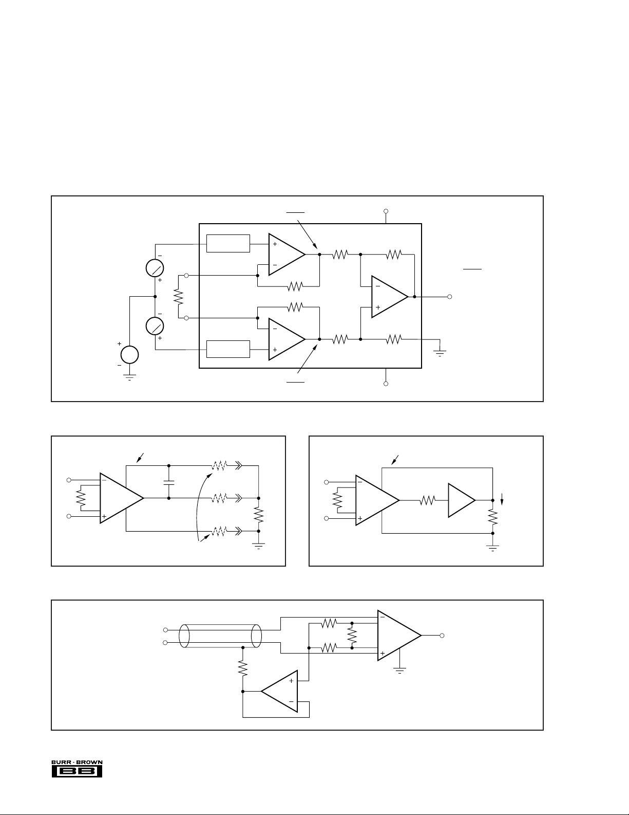
current limit behavior. The inputs are protected even if no
g
power supply voltage is present.
OUTPUT VOLTAGE SENSE (SOL-16 package only)
The surface-mount version of the INA114 has a separate
output sense feedback connection (pin 12). Pin 12 must be
connected to the output terminal (pin 11) for proper operation. (This connection is made internally on the DIP version
of the INA114.)
The output sense connection can be used to sense the output
voltage directly at the load for best accuracy. Figure 5 shows
how to drive a load through series interconnection resistance. Remotely located feedback paths may cause instability. This can be generally be eliminated with a high
frequency feedback path through C
. Heavy loads or long
1
lines can be driven by connecting a buffer inside the feedback path (Figure 6).
V
D
2
V
D
2
V
CM
FIGURE 4. Voltage Swing of A
Surface-mount package
version only.
–
V
IN
R
G
+
V
IN
Output
Sense
INA114
Ref
R
and A2.
1
C
1
1000pF
G
Over-Voltage
Protection
Over-Voltage
Protection
VCM –
VCM +
Load
A
A
G • V
1
25kΩ
25kΩ
2
G • V
INA114
V+
INA114
25kΩ25kΩ
A
3
25kΩ25kΩ
V–
Surface-mount package
version only.
Output
Sense
Ref
180Ω
G = 1 +
V
O
OPA633
50kΩ
R
G
= G • V
D
IL: ±100mA
R
L
D
2
D
2
–
V
IN
R
G
+
V
IN
Equal resistance here preserves
ood common-mode rejection.
FIGURE 5. Remote Load and Ground Sensing. FIGURE 6. Buffered Output for Heavy Loads.
–
V
IN
+
V
IN
Shield is driven at the
common-mode potential.
100Ω
OPA602
22.1kΩ
22.1kΩ
For G = 100
= 511Ω // 2(22.1kΩ)
R
G
effective R
511Ω
= 505Ω
G
INA114
Ref
V
O
FIGURE 7. Shield Driver Circuit.
®
INA114
10
Page 11
Equal line resistance here creates
j
a small common-mode voltage
which is rejected by INA114.
1
RTD
2
3
Resistance in this line causes
a small common-mode voltage
which is re
ected by INA114.
FIGURE 8. RTD Temperature Measurement Circuit.
V+ V+
REF200
100µA
R
Z
V
R
INA114
G
O
Ref
= 0V at R
V
O
RTD
= R
Z
V+
2
10.0V
R
1
Ω
27k
1N4148
(1)
Cu
K
Cu
R
2
5.23k
R
3
100
Ω
Ω
R
1M
(2)
7
Ω
SEEBECK
ISA COEFFICIENT R
TYPE MATERIAL (µV/°C) (R3 = 100Ω)(R5 + R6 = 100Ω)
2
R
4
E Chromel 58.5 3.48kΩ 56.2kΩ
Constantan
J Iron 50.2 4.12kΩ 64.9kΩ
Constantan
K Chromel 39.4 5.23kΩ 80.6kΩ
Alumel
T Copper 38.0 5.49kΩ 84.5kΩ
Constantan
NOTES: (1) –2.1mV/°C at 200µA. (2) R
provides down-scale burn-out indication.
7
R
4
80.6k
R
5
Ω
50
6
REF102
Ω
R
6
Ω
100
Zero Adj
4
INA114
Ref
V
O
FIGURE 9. Thermocouple Amplifier With Cold Junction Compensation.
11
®
INA114
Page 12
RA
LA
390kΩ
RL
390kΩ
1/2
OPA2604
FIGURE 10. ECG Amplifier With Right-Leg Drive.
10kΩ
1/2
OPA2604
2.8kΩ
R
G/2
INA114
Ref
V
O
G = 102.8kΩ
+10V
Bridge
R
100Ω
G
G = 500
INA114
FIGURE 11. Bridge Transducer Amplifier.
–
V
R
IN
+
A
1
G
INA114
IB Error
OPA177 ±1.5nA
OPA602 1pA
OPA128 75fA
Ref
R
1
I
B
A
1
Ref
I
Load
V
= • G
O
R
–
V
R
G
INA114
Ref
C
0.1µF
1
IN
+
V
O
OPA602
R
1MΩ
V
O
1
f
–3dB
1
=
2πR
1C1
= 1.59Hz
FIGURE 12. AC-Coupled Instrumentation Amplifier.
IN
I
O
FIGURE 13. Differential Voltage-to-Current Converter.
®
INA114
12
Page 13
PACKAGE OPTION ADDENDUM
www.ti.com
26-Jan-2007
PACKAGING INFORMATION
Orderable Device Status
(1)
Package
Type
Package
Drawing
Pins Package
Qty
Eco Plan
INA114AP ACTIVE PDIP P 8 50 Green (RoHS &
no Sb/Br)
INA114APG4 ACTIVE PDIP P 8 50 Green (RoHS &
no Sb/Br)
INA114AU ACTIVE SOIC DW 16 48 Green (RoHS &
no Sb/Br)
INA114AU/1K ACTIVE SOIC DW 16 1 Pb-Free
INA114AU/1KE4 ACTIVE SOIC DW 16 1 Green (RoHS &
no Sb/Br)
INA114AUE4 ACTIVE SOIC DW 16 48 Green (RoHS &
no Sb/Br)
INA114AUG4 ACTIVE SOIC DW 16 48 Green (RoHS &
no Sb/Br)
INA114BP ACTIVE PDIP P 8 50 Green (RoHS &
no Sb/Br)
INA114BPG4 ACTIVE PDIP P 8 50 Green (RoHS &
no Sb/Br)
INA114BU ACTIVE SOIC DW 16 48 Pb-Free
INA114BU/1K ACTIVE SOIC DW 16 1000 Pb-Free
INA114BU/1KE4 ACTIVE SOIC DW 16 1000 Pb-Free
INA114BUE4 ACTIVE SOIC DW 16 48 Pb-Free
(1)
The marketing status values are defined as follows:
ACTIVE: Product device recommended for new designs.
LIFEBUY: TI has announced that the device will be discontinued, and a lifetime-buy period is in effect.
NRND: Not recommended for new designs. Device is in production to support existing customers, but TI does not recommend using this part in
a new design.
PREVIEW: Device has been announced but is not in production. Samples may or may not be available.
OBSOLETE: TI has discontinued the production of the device.
(RoHS)
(RoHS)
(RoHS)
(RoHS)
(RoHS)
(2)
Lead/Ball Finish MSL Peak Temp
CU NIPDAU N / A for Pkg Type
CU NIPDAU N / A for Pkg Type
CU NIPDAU Level-3-260C-168 HR
CU NIPDAU Level-3-260C-168 HR
CU NIPDAU Level-3-260C-168 HR
CU NIPDAU Level-3-260C-168 HR
CU NIPDAU Level-3-260C-168 HR
CU NIPDAU N / A for Pkg Type
CU NIPDAU N / A for Pkg Type
CU NIPDAU Level-3-260C-168 HR
CU NIPDAU Level-3-260C-168 HR
CU NIPDAU Level-3-260C-168 HR
CU NIPDAU Level-3-260C-168 HR
(3)
(2)
Eco Plan - The planned eco-friendly classification: Pb-Free (RoHS), Pb-Free (RoHS Exempt), or Green (RoHS & no Sb/Br) - please check
http://www.ti.com/productcontent for the latest availability information and additional product content details.
TBD: The Pb-Free/Green conversion plan has not been defined.
Pb-Free (RoHS): TI's terms "Lead-Free" or "Pb-Free" mean semiconductor products that are compatible with the current RoHS requirements
for all 6 substances, including the requirement that lead not exceed 0.1% by weight in homogeneous materials. Where designed to be soldered
at high temperatures, TI Pb-Free products are suitable for use in specified lead-free processes.
Pb-Free (RoHS Exempt): This component has a RoHS exemption for either 1) lead-based flip-chip solder bumps used between the die and
package, or 2) lead-based die adhesive used between the die and leadframe. The component is otherwise considered Pb-Free (RoHS
compatible) as defined above.
Green (RoHS & no Sb/Br): TI defines "Green" to mean Pb-Free (RoHS compatible), and free of Bromine (Br) and Antimony (Sb) based flame
retardants (Br or Sb do not exceed 0.1% by weight in homogeneous material)
(3)
MSL, Peak Temp. -- The Moisture Sensitivity Level rating according to the JEDEC industry standard classifications, and peak solder
temperature.
Important Information and Disclaimer:The information provided on this page represents TI's knowledge and belief as of the date that it is
provided. TI bases its knowledge and belief on information provided by third parties, and makes no representation or warranty as to the
accuracy of such information. Efforts are underway to better integrate information from third parties. TI has taken and continues to take
reasonable steps to provide representative and accurate information but may not have conducted destructive testing or chemical analysis on
Addendum-Page 1
Page 14

PACKAGE OPTION ADDENDUM
www.ti.com
incoming materials and chemicals. TI and TI suppliers consider certain information to be proprietary, and thus CAS numbers and other limited
information may not be available for release.
In no event shall TI's liability arising out of such information exceed the total purchase price of the TI part(s) at issue in this document sold by TI
to Customer on an annual basis.
26-Jan-2007
Addendum-Page 2
Page 15

IMPORTANT NOTICE
Texas Instruments Incorporated and its subsidiaries (TI) reserve the right to make corrections, modifications,
enhancements, improvements, and other changes to its products and services at any time and to
discontinue any product or service without notice. Customers should obtain the latest relevant information
before placing orders and should verify that such information is current and complete. All products are sold
subject to TI’s terms and conditions of sale supplied at the time of order acknowledgment.
TI warrants performance of its hardware products to the specifications applicable at the time of sale in
accordance with TI’s standard warranty. Testing and other quality control techniques are used to the extent
TI deems necessary to support this warranty. Except where mandated by government requirements, testing
of all parameters of each product is not necessarily performed.
TI assumes no liability for applications assistance or customer product design. Customers are responsible
for their products and applications using TI components. To minimize the risks associated with customer
products and applications, customers should provide adequate design and operating safeguards.
TI does not warrant or represent that any license, either express or implied, is granted under any TI patent
right, copyright, mask work right, or other TI intellectual property right relating to any combination, machine,
or process in which TI products or services are used. Information published by TI regarding third-party
products or services does not constitute a license from TI to use such products or services or a warranty or
endorsement thereof. Use of such information may require a license from a third party under the patents or
other intellectual property of the third party, or a license from TI under the patents or other intellectual
property of TI.
Reproduction of information in TI data books or data sheets is permissible only if reproduction is without
alteration and is accompanied by all associated warranties, conditions, limitations, and notices.
Reproduction of this information with alteration is an unfair and deceptive business practice. TI is not
responsible or liable for such altered documentation.
Resale of TI products or services with statements different from or beyond the parameters stated by TI for
that product or service voids all express and any implied warranties for the associated TI product or service
and is an unfair and deceptive business practice. TI is not responsible or liable for any such statements.
Following are URLs where you can obtain information on other Texas Instruments products and application
solutions:
Products
Applications
Amplifiers amplifier.ti.com Audio www.ti.com/audio
Data Converters dataconverter.ti.com Automotive www.ti.com/automotive
DSP dsp.ti.com Broadband www.ti.com/broadband
Interface interface.ti.com Digital Control www.ti.com/digitalcontrol
Logic logic.ti.com Military www.ti.com/military
Power Mgmt power.ti.com Optical Networking www.ti.com/opticalnetwork
Microcontrollers microcontroller.ti.com Security www.ti.com/security
Low Power Wireless www.ti.com/lpw Telephony www.ti.com/telephony
Video & Imaging www.ti.com/video
Wireless www.ti.com/wireless
Mailing Address: Texas Instruments
Post Office Box 655303 Dallas, Texas 75265
Copyright © 2007, Texas Instruments Incorporated
 Loading...