

Page 1
TECHNICAL DATA
1
13 Memory Tone/Pulse Dialer with
Handfree and Hold Function
The IN91350A is a silicon CMOS IC that provide necessary signal for
either Pulse or Tone dialing. It features Handfree dialing, Hold, and
13 by 16 digits automatic dialing memory.
•
DTMF/PULSE switchable dialer
•
32 digits for Redial memory
•
Three by 16 digits for one touch direct repertory
•
Ten by 16 digits for two touch indirect repertory
•
Mix dialing is allowable, and the dialing length is unlimited
•
Pulse to Tone (*/T) keypad for Long Distance Call operation
•
Easy operation with Redial, Flash, Pause and */T keypads
•
Pause, P- - >T (Pulse to Tone) can be stored as a digit in memory
•
Flash time 600 mS
•
4 x 5 keyboard can be used
•
Power on reset on chip
•
Use 3.579545 MHz crystal or ceramic resonator
•
Dial Pulse Rate: 10 pps
IN91350A
ORDERING INFORMATION
IN91350AN
TA = -20° to 70° C
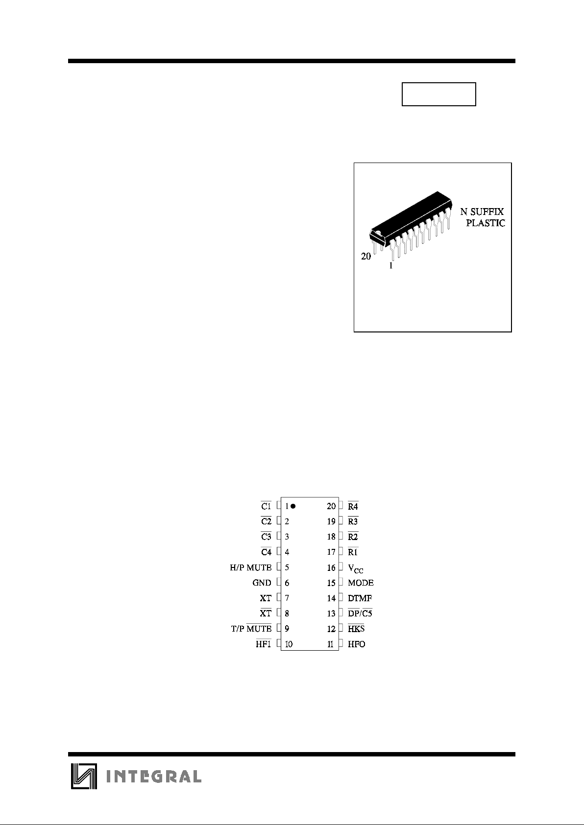
PIN ASSIGNMENT
Page 2
IN91350A
2
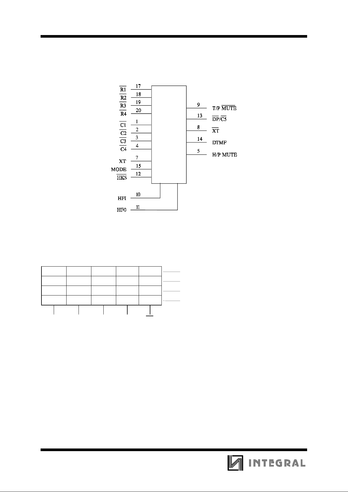
LOGIC DIAGRAM
PIN 6= GND
PIN 16 = V
CC
Keyboard Assignments
123STM1 R1
456FM2 R2
789AM3 R3
*/T 0 # R/P H R4
C1 C2 C3 C4 C5
Notes:
1. M1 ∼ M3 - One touch memory. The dialing number c an be stored in M1 ∼ M3 location by STORE key.
2. ST - Store functi on key.
3. H - Hold function key.
4. F - Flash key.
Flash key can not be stored in memory.
5. */T - In the Pulse mode this key works as Pulse - - >Tone key, and it works as * key in the tone mode.
*/T key can be stored as a digit in Pulse or Tone mode.
6. R/P - Redial and Pause function key.
The Redial function can be executed only in first key-in after OFF HOOK, otherwise will be operated as
Pause function.
7. A - Indirect r epertory dialing function key.
Page 3
IN91350A
3
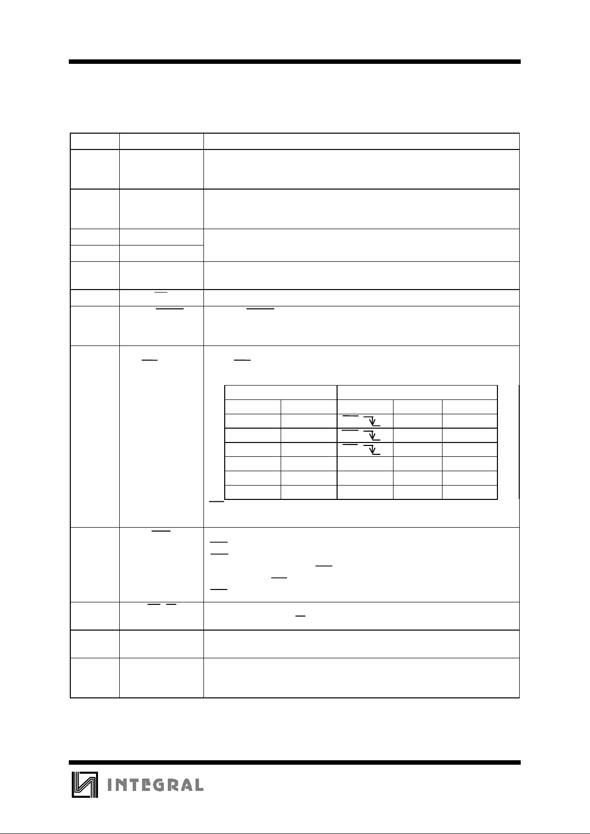
Pin Description
Pin No. Designation Description
1 - 4
17 - 20
Column-Row
Inputs
The Keyboard input may be used with the standard 4 x 5 keyboard.
A valid key entry is define d by a single row being connected to a single
column.
5 H/P MUTE The H/P MUTE is a conventional inverter output.
In pulse dialing, flash and hold period, the output will be at active high,
otherwise, it will keep at low state.
6 GND
16 V
CC
7 XT A built in inverter provides oscillation with an inexpensive 3.579545 MHz
crystal or ceramic resonator.
8 XT The oscillator output pin.
9 T/P MUTE The T/P MUTE is a conventional CMOS N-channel open drain output.
The output transistor is switched on during Pulse and Tone mode dialing
sequence and Flash break. Ohterwise, it is switched off.
10, 11 HFI, HF0
Handfree control pins.
When HFI input pin has a low pulse, the handfree control state is toggled on.
Status of the handfree control state is listed in the following table:
CURRENT STATE NEXT STATE
Hook SW. HFO Input HFO Dialing?
XLowHFI HighYes
On Hook High HFI Low No
Off Hook High HFI Low Yes
On Hook X Off Hook Low Yes
Off Hook Low On Hook Low No
Off Hook High On Hook High Yes
HFI pin is pulled to V
CC
by internal resistor.
X = don’t care.
12 HKS This pin is the hook switch input.
HKS = H, ON HOOK state, chip in sleeping mode, no operation.
HKS = L, OFF HOOK state, enable chip on normal operation.
This pin must combine to HFI, HFO to perform the above function.
Please refer to HFI, HFO pin.
HKS pin is pulled to V
CC
by internal resistor.
13 DP/C5 Open drain dialing pulse output.
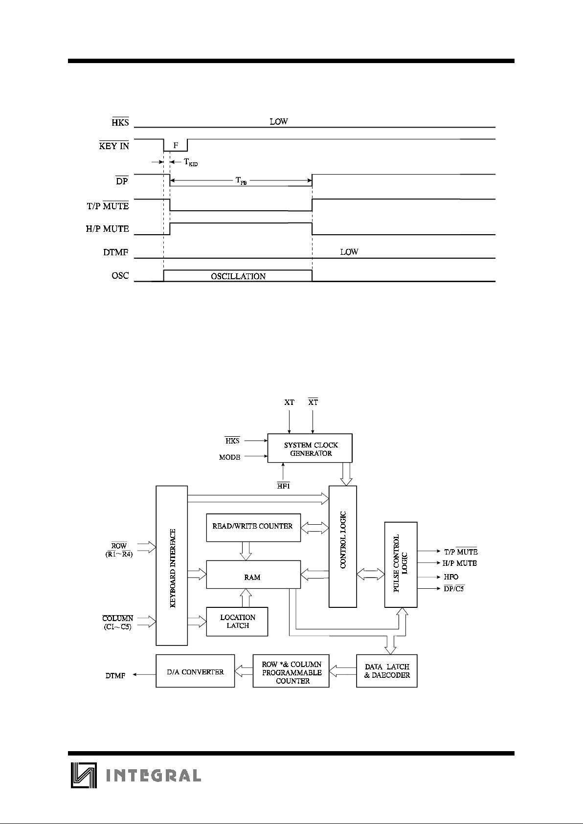
Flash key will cause DP active either in Tone mode or Pulse mode.
14 DTMF In pulse mode, it always keeps at low state.
In tone mode, it will output a dual or single tone.
15 MODE Pull mode pin to GND; the dialer is in Tone mode.
Pull mode pin to V
CC
; the dialer is in Pulse mode - 10 pps, M/B=2/3.
Pull mode pin to floating; the dialer is in Pulse mode - 10 pps, M/B=1/2.
Power supply pins.
This device is designed to operate from 2.0 V to 5.5 V.
Page 4

IN91350A
4
Operation Procedures
:
Symbol Definitions
In the description below, signals are defined in
terms of the key or switch which is activated.
Off Hook
means the phone was taken off
the hook.
On Hook
means that the receiver is on the
hook.
D1
or
L1
stands for the first digit dialed
in a string of digits.
Dn
or
Ln
stands for the last digit dialed
in a string of digits.
Dn+1
stands for the beginning of a new
string of digits.
Dn+m
stands for the last digit in a new string
of digits.
Input Level from High to Low.
Mn=M1∼M3; Ln=0∼9; Dn=0∼9,*,#,Pause.
1. Normal Dialing
Off Hook (or On Hook &
HFI
),
D1 , D2 , ... , Dn
1. D1, D2, ... , Dn will be dialed out.
2. Dialing length is unlimited, but the Redial is
inhibited if it oversteps 32 digits.
2. Redialing
Off Hook , D1 , D2 , .. , Dn , BUSY,
Come On Hook , Off Hook (or On Hook &
HFI ), R/P (or On Hook &
HFI , D1 , D2 , ... , Dn ,BUSY,
HFI ,Come HFI , R/P
The R/P key can execute Redial function only in
first key-in after Off Hook, otherwise it will be
Pause function.
3. Number store
1. Off Hook (or On Hook & HFI ),
D1 , D2 ,..., Dn , ST , ST , Mn or Ln
On Hook (or On Hook & HFI )
a. The dialing of D1, D2, ... , Dn must have
finished, then ST key may be pressed.
b. D1, D2, ... , Dn will be stored in Mn or Ln
memory location and they will be dialed out.
2. Off Hook (or On Hook & HFI ),
ST , D1 , D2 ,..., Dn , ST , Mn or Ln
On Hook (or On Hook & HFI )
a. D1, D2, ... , Dn will be stored in Mn or Ln
memory location but they will not be dialed out.
b. R/P and */T keys can be stored as a digit in
memory. In store mode, R/P in the pause
function key.
c. The store mode can be release after the store
function is executed or the present state of hook
switch is changed.
4. Repertory Dialing
1. Off Hook (or On Hook &
HFI
)Mn
2. Off Hook (or On Hook &
HFI
)
A,
Ln
5. Access Pause
Off Hook (or On Hook &
HFI
),
D1 , D2 , R/P , D3 , ... , Dn
1. The Pause function can be stored in memory.
2. The Pause function is executed in normal dialing
or Redialing or memory dialing.
6. Pulse to Tone (*/T)
Off Hook (or On Hook &
HFI
),
D1 , D2 , ... , Dn , */T ,
Dn+1 , Dn+2 , ... , Dn+m
1. If the mode switch is set in Pulse mode, then the
output signal will be:
D1, D2, ... , Dn, Pause
(Pulse)
Dn+1, Dn+2, ... , Dn+m
(Tone)
2. If the mode switch is set in Tone mode, then the
output signal will be:
D1, D2, ... , Dn,
(Tone)
, * , Dn+1, Dn+2, ... , Dn+m
(Tone) (Tone)
3. It can be reset to Pulse mode only in operation of
On Hook, because it’s still in Tone mode when
the digits have been dialed out.
Page 5
IN91350A
2
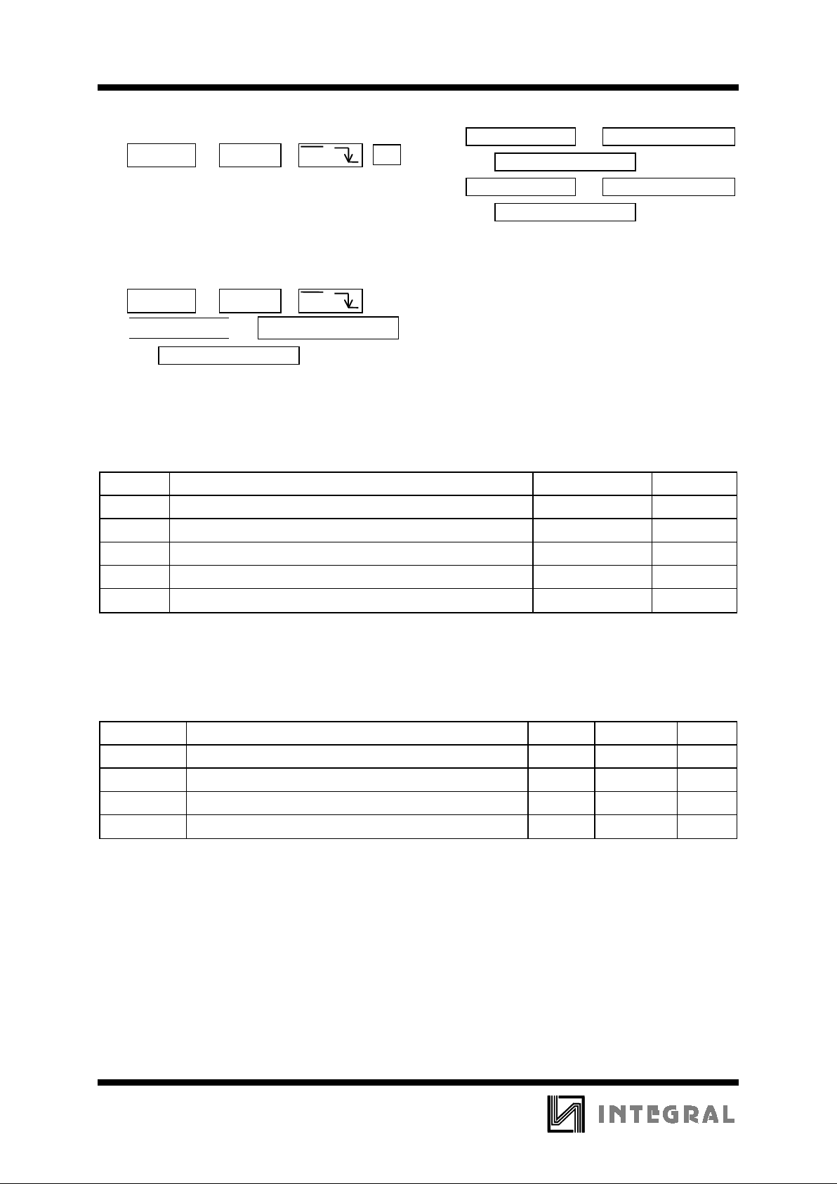
7. Flash
Off Hook (or On Hook &
HFI
)
F
1. Flash key can not be stored as a digit in memory
and it has the first priority of the keyboard
function.
2. The system will return to the initial state after the
break time is finished.
8. Mix Dialing
Off Hook (or On Hook &
HFI
)
1.
Normal dialing
+ Repertory dialing
+ Normal dialing
2. Repertory dialing + Normal dialing
+ Repertory dialing
3. Redialing + Normal dialing
+ Repertory dialing
a. Redialing and Save dia ling are valid j ust for first
key in.
b. The second sequence should not be operated until
the first sequence is dialed out completely.
MAXIMUM RATINGS
*
Symbol Parameter Value Unit
V
CC
DC Supply Voltage (Referenced to GND) -0.3 to +7.0 V
V
IN
DC Input Voltage (Referenced to GND) -0.3 to VCC +0.3 V
V
OUT
DC Output Voltage (Referenced to GND) -0.3 to VCC +0.3 V
P
D
Power Dissipation in Still Air, Plastic DIP
**
500 mW
Tstg Storage Temperature -55 to +150
°
C
*
Maximum Ratings are those values beyond which damage to the device may occur.
Functional operation should be restricted to the Recommended Operating Conditions.
**
Durating: -10 mW/
°
C
from 65°C to 70°C.
RECOMMENDED OPERATING CONDITIONS
Symbol Parameter Min Max Unit
V
CC
DC Supply Voltage (Referenced to GND) 2.0 5.5 V
V
IN
DC Input Voltage (Referenced to GND) 0 V
CC
V
V
OUT
DC Output Voltage (Referenced to GND) 0 V
CC
V
T
A
Operating Temperature -20 +70
°
C
This device c ontains p rote ction ci rcuitr y to guard a gainst damage d ue to high st atic voltages or electr ic
fields. However, precautions must be taken to avoid applications of any voltage higher than maximum rated
voltages to this high-impedance circuit. For proper operation, V
IN
and V
OUT
should be constrained to the range
GND≤(V
IN
or V
OUT
)≤VCC.
Unused inputs must always be tied to an appropriate logic voltage level (e.g., either GND or V
CC
).
Unused outputs must be left open.
Page 6
IN91350A
2
All outputs
unloaded
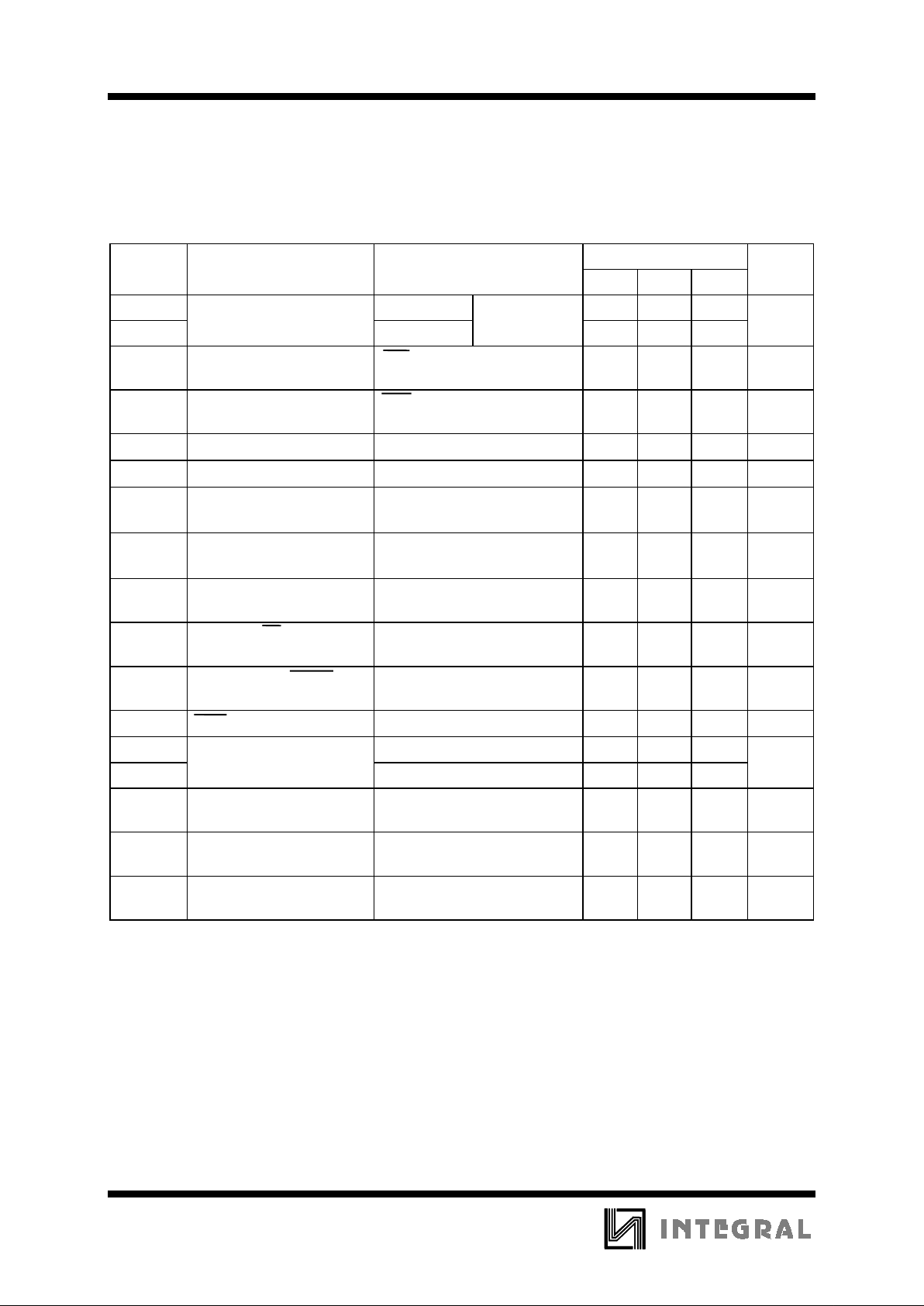
DC ELECTRICAL CHARACTERISTICS
(Voltages Referenced to GND, VCC =2.5 V,
T
A
=25°C*, F
OSC
. = 3.58 MHz)
Guaranteed Limits
Symbol Parameter Test Conditions Min Typ Max Unit
I
CCT
Tone mode - 0.50
I
CCP
Pulse mode - 0.30
I
SB
Maximum Standby Cu rrent HKS = 0
No load & No key entry
-15
µ
A
I
MR
Maximum Memory
Retention Current
HKS = H
V
CC
= 1.0 V
-0.2
µ
A
V
TO
DTMF Output Voltage
Row group, R
L
= 5 k
Ω
130 170 mVrms
T
WIST
Pre-emphasis
Col/Row, V
CC
= 2.0 ∼ 5.5 V
13dB
T
HD
DTMF Distortion
R
L
= 5 kΩ,
V
CC
= 2.0 ∼ 5.5 V
- -23 dB
V
TDC
DTMF Output DC Level
R
L
= 5 kΩ,
V
CC
= 2.0 ∼ 5.5 V
1.1 2.8 V
I
TL
Minimum DTMF Sink
Output Current
VTO = 0.5 V 0.2 mA
I
PL
Minimum DP Sink Output
Current
VPO = 0.5 V 0.5 mA
I
ML
Minimum T/P MUTE Sink
Output Current
VMO = 0.5 V 0.5 mA
R
KH
HKS I/P Pull High Resister 300
k
Ω
I
HFH
V
HFH
= 2.0 V 0.5 -
I
HFL
V
HFL
= 0.5 V 0.5 -
I
Kd
Keypad Input Drive
Current
V
IN
= 0 V 4 30
µ
A
I
KS
Mini mum Keypad Input
Sink Current
V
IN
= 2.5 V 200 -
µ
A
Maximum Keyp ad
Resistance
-5.0
k
Ω
* - from -20°C to +70°C values of parameters are specifying.
Maximum Ope rating
Current
Minimum HFO Drive/Sink
Current
mA
mA
Page 7
IN91350A
3
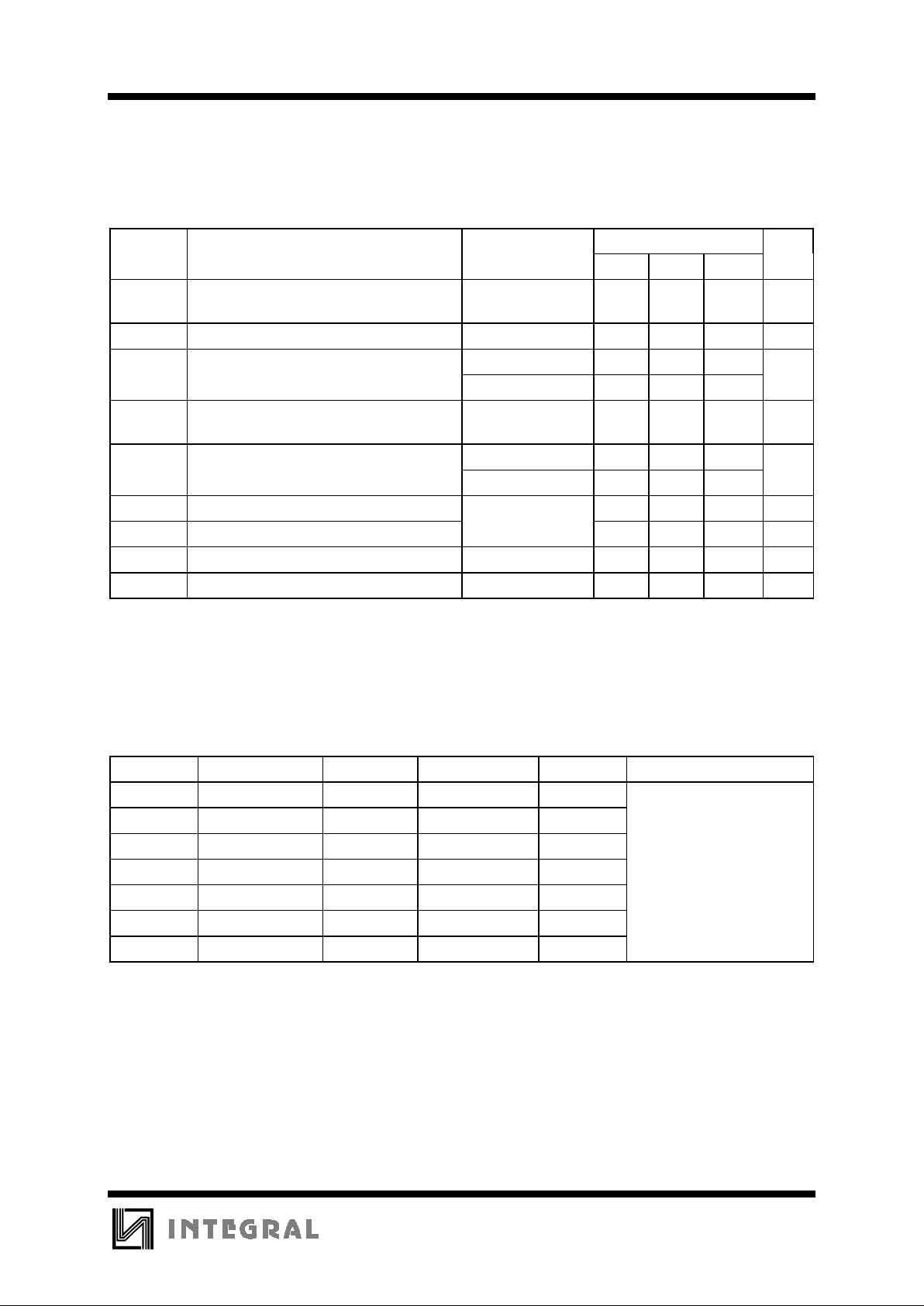
AC ELECTRICAL CHARACTERISTICS
(All Voltages referenced to GND. VCC= 2.0 V to 5.5 V,
T
A
= 25°C*)
Guaranteed Limits
Symbol Parameter Test Conditions Min Typ Max Unit
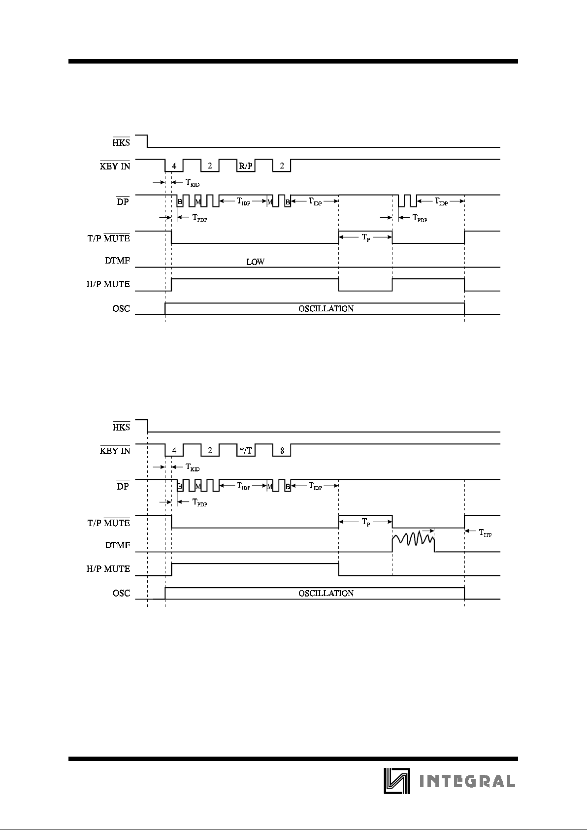
T
KID
Keypad Active in Debounce
(Figures 1,2,4-6)
-20 -ms
T
KRD
Key Release Debounce (Figure 2) - 20 - ms
M/B = 2/3 - 40 M/B = 1/2 - 33.3 -
T
IDP
Inter Digit P ause Time (Auto Dialing)
(Figures 1,2,4,5)
- 800 - ms
M/B = 2/3 - 40/60 M/B = 1/2 - 33/67 -
T
TD
DTMF Output Duration (Figure 2) - 100 - ms
T
ITP
Inter Tone Pause (Figure 2) - 100 - ms
T
FB
Flash Break Time (Figure 6) - 600 - ms
T
P
Pause Time (Fi gure 5) - 3.6 - s
* - from -20°C to +70°C values of parameters are specifying
Comparisons of Specified vs. Actual Tone Frequencies
R/C Spec. Actual Error(%) Unit Conditions
R1 697 699 +0.28 Hz
R2 770 766 -0.52 Hz
R3 852 848 -0.47 Hz
R4 941 948 +0.74 Hz F
OSC
= 3.579 MHz
C1 1209 1216 +0.57 Hz
C2 1336 1332 -0.30 Hz
C3 1477 1472 -0.34 Hz
T
PDP
M/B
Pre-Digit-Pause (Figures 1,4 ,5)
Make/Break Ratio
ms
%
Auto Dialing
Page 8
IN91350A
4
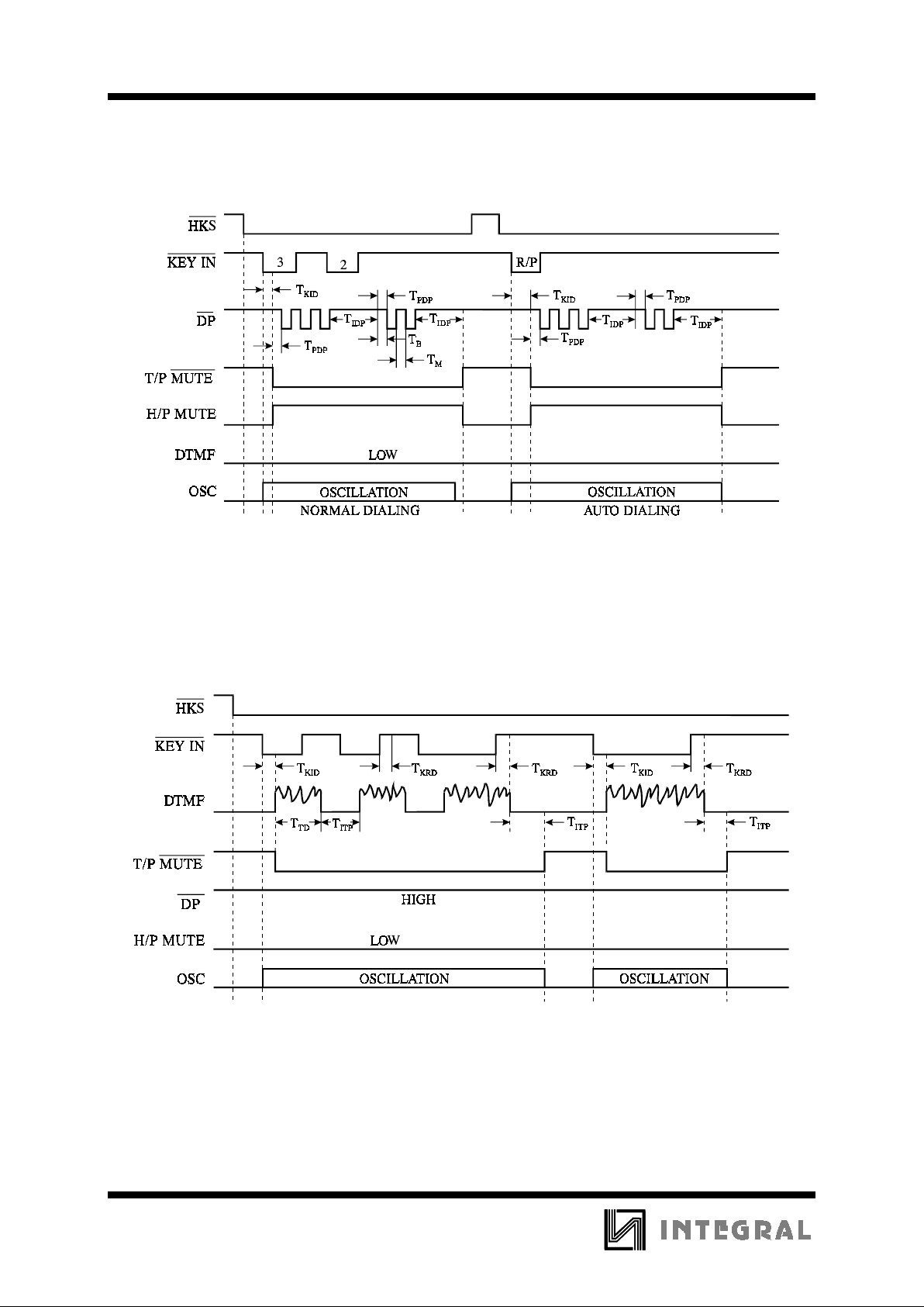
Figure 1. Pulse Mode
Figure 2(a). Tone Mode Normal Dialing
Page 9
IN91350A
5
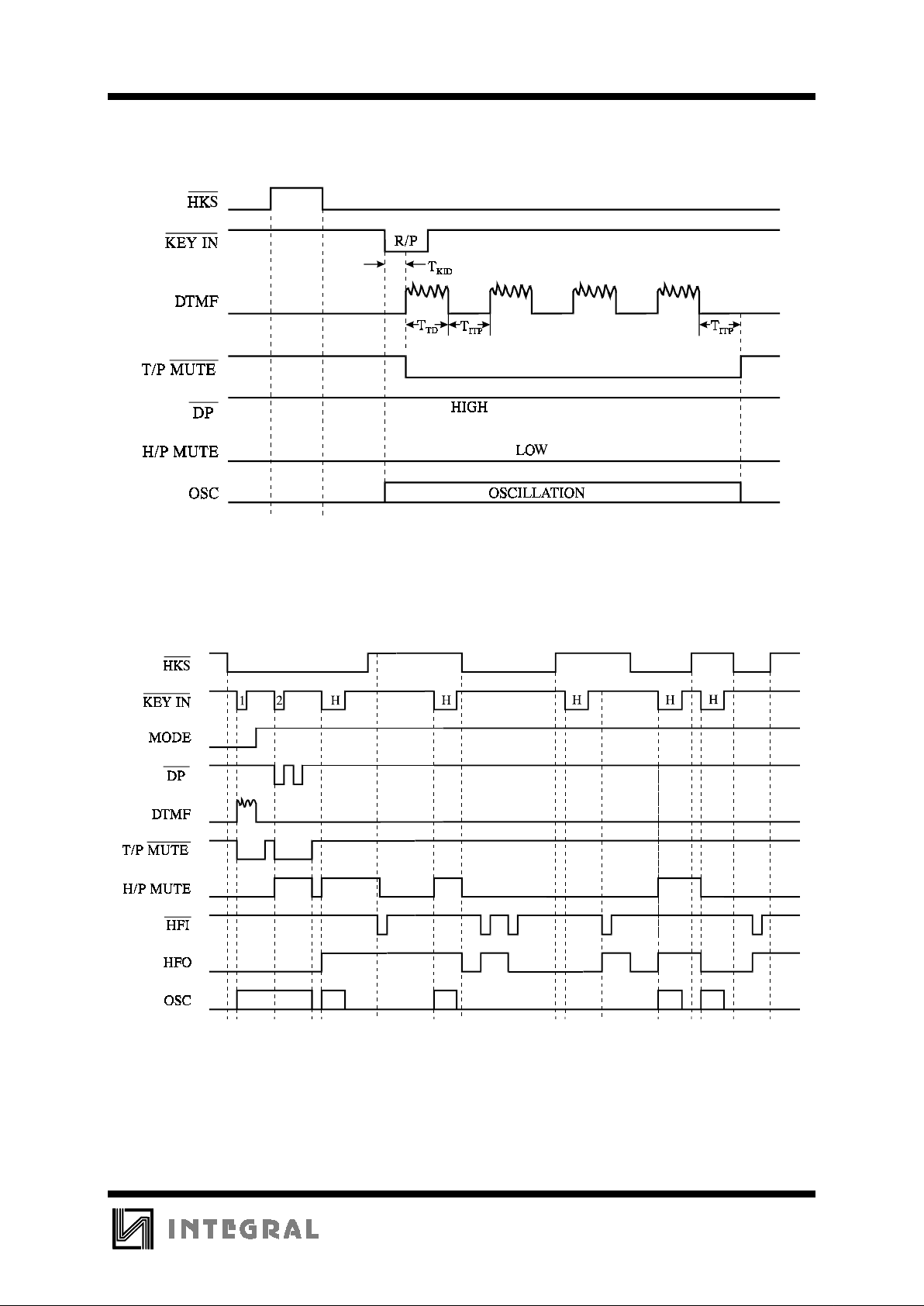
Figure 2(b). Tone Mode Auto Dia ling
Figure 3. Control Function and Hold Function Relationship
Page 10
IN91350A
6
Figure 4. Pause Function
Figure 5. P - - >T Operation in Normal Dialing
Page 11
IN91350A
7
Figure 6. Flash Operatio
EXPANDED LOGIC DIAGRAM
 Loading...