

Page 1
Presettable Counters
High-Performance Silicon-Gate CMOS
The IN74HC161A is identical in pinout to the LS/ALS161. The
device inputs are compatible with standard CMOS outputs; with pullup
resistors, they are compatible with LS/ALSTTL outputs.
The IN74HC161A is programmable 4-bit synchronous counter that
feature parallel Load, asynchronous Reset, a Carry Output for
cascading and count-enable controls.
The IN74HC161A is binary counter with asynchronous Reset.
•
Outputs Directly Interface to CMOS, NMOS, and TTL
•
Operating Voltage Range: 2.0 to 6.0 V
•
Low Input Current: 1.0 µA
•
High Noise Immunity Characteristic of CMOS Devices
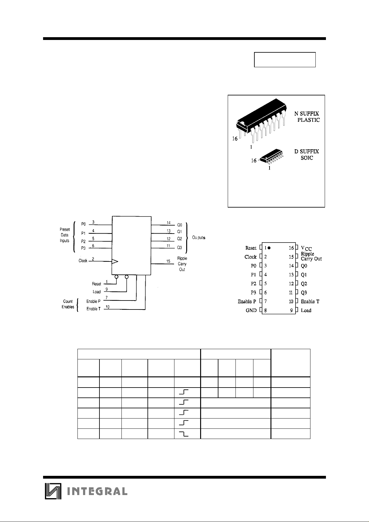
LOGIC DIAGRAM
TECHNICAL DATA
IN74HC161A
ORDERING INFORMATION
IN74HC161AN Plastic
IN74HC161AD SOIC
TA = -55° to 125° C for all packages
PIN ASSIGNMENT
PIN 16 =V
PIN 8 = GND
CC
FUNCTION TABLE
Inputs Outputs
Reset Load EnablePEnableTClockQ0Q1Q2Q3 Function
L X X X X L L L L Reset to “0”
H L X X P0 P1 P2 P3 Preset Data
H H X L No change No count
H H L X No change No count
H H H H Count up Count
H X X X No change No count
X=don’t care
P0,P1,P2,P3 = logic level of Data inputs
Ripple Carry Out = Enable T • Q0 • Q1 • Q2 • Q3
197
Page 2
IN74HC161A
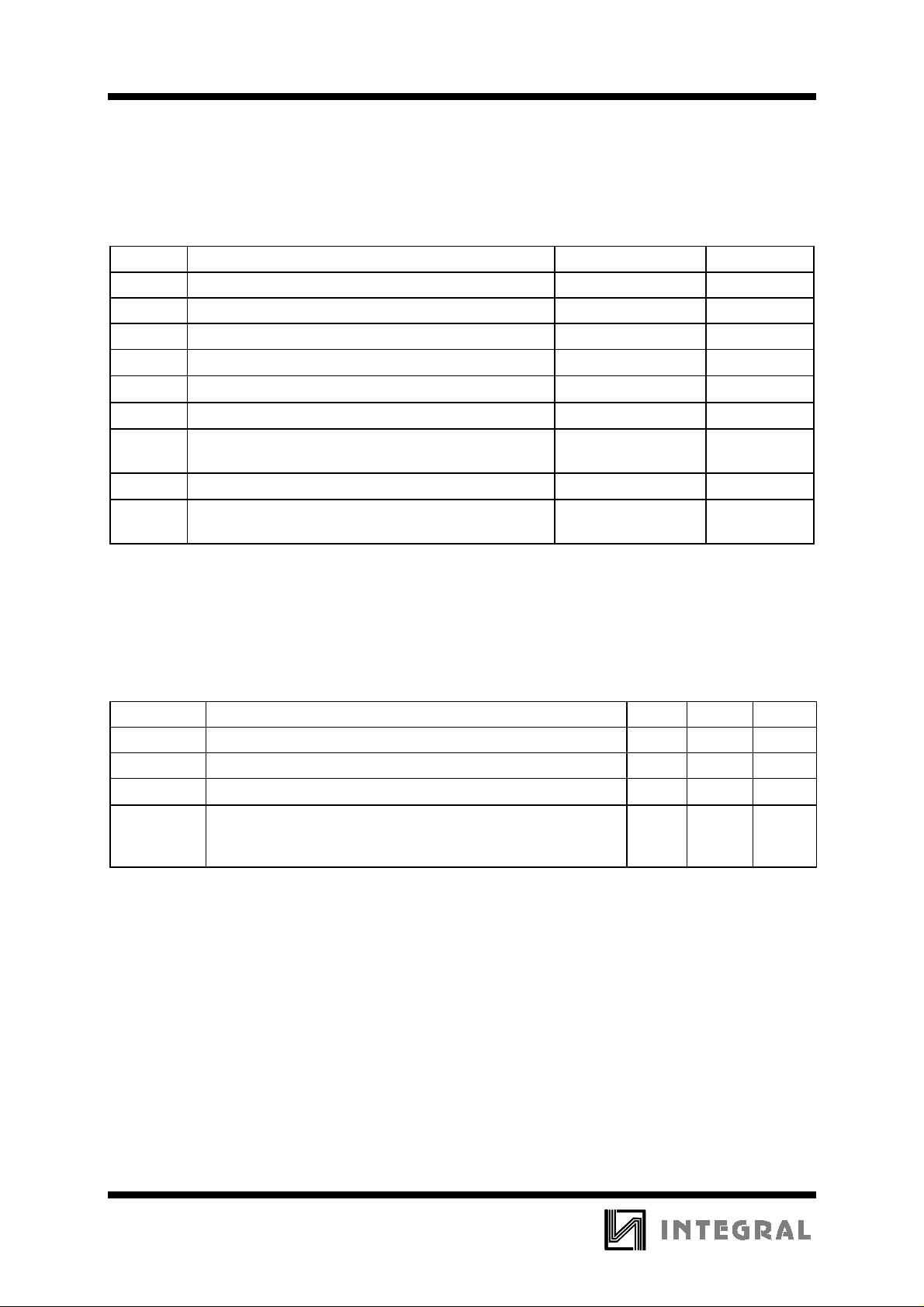
MAXIMUM RATINGS
*
Symbol Parameter Value Unit
V
CC
V
V
OUT
I
IN
I
OUT
I
CC
P
DC Supply Voltage (Referenced to GND) -0.5 to +7.0 V
DC Input Voltage (Referenced to GND) -1.5 to VCC +1.5 V
IN
DC Output Voltage (Referenced to GND) -0.5 to VCC +0.5 V
DC Input Current, per Pin
DC Output Current, per Pin
DC Supply Current, VCC and GND Pins
Power Dissipation in Still Air, Plastic DIP+
D
SOIC Package+
±
20
±
25
±
50
750
500
Tstg Storage Temperature -65 to +150
T
Lead Temperature, 1 mm from Case for 10 Seconds
L
260
(Plastic DIP or SOIC Package)
*
Maximum Ratings are those values beyond which damage to the device may occur.
Functional operation should be restricted to the Recommended Operating Conditions.
+Derating - Plastic DIP: - 10 mW/°C from 65° to 125°C
SOIC Package: : - 7 mW/°C from 65° to 125°C
mA
mA
mA
mW
°
C
°
C
RECOMMENDED OPERATING CONDITIONS
Symbol Parameter Min Max Unit
V
CC
VIN, V
T
A
tr, t
f
This device c ontains p rote ction ci rcuitr y to guard a gainst damage d ue to high st atic voltages or electr ic
fields. However, precautions must be taken to avoid applications of any voltage higher than maximum rated
voltages to this high-impedance circuit. For proper operation, V
GND≤(V
Unused inputs must always be tied to an appropriate logic voltage level (e.g., either GND or V
Unused outputs must be left open.
DC Supply Voltage (Referenced to GND) 2.0 6.0 V
DC Input Voltage, Output Voltage (Referenced to GND) 0 V
OUT
Operating Temperature, All Package Types -55 +125
Input Rise and Fall Time (Figure 1) VCC =2.0 V
IN
or V
OUT
)≤VCC.
V
V
and V
IN
=4.5 V
CC
=6.0 V
CC
should be constrained to the range
OUT
0
0
0
CC
1000
500
400
V
°
C
ns
CC
).
198
Page 3
IN74HC161A
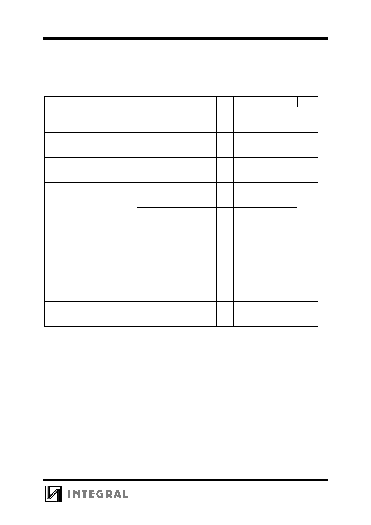
DC ELECTRICAL CHARACTERISTICS
(Voltages Referenced to GND)
Symbol Parameter Test Conditions V
V
V
V
OH
V
OL
I
IN
Minimum High-Level
IH
Input Voltage
Maximum Low -
IL
Level Input Voltage
Minimum High-Level
Output Voltage
Maximum Low-Level
Output Voltage
Maximum Input
V
=0.1 V or VCC-0.1 V
OUT
≤
I
20 µA
OUT
V
=0.1 V or VCC-0.1 V
OUT
≤
I
20 µA
OUT
VIN=VIH or V
≤
I
OUT
VIN=VIH or V
≤
I
OUT
≤
I
OUT
VIN=VIH or V
≤
I
OUT
VIN=VIH or V
≤
I
OUT
≤
I
OUT
IL
20 µA
IL
6.0 mA
7.8 mA
IL
20 µA
IL
6.0 mA
7.8 mA
VIN=VCC or GND 6.0
Leakage Current
I
CC
Maximum Qui escent
Supply Current
VIN=VCC or GND
=0µA
I
OUT
(per Package)
V
CC
Guaranteed Limit
25 °C
to
≤
85
°
C
≤
125
°
-55°C
2.0
4.5
6.0
2.0
4.5
6.0
2.0
4.5
6.0
4.5
6.0
2.0
4.5
6.0
4.5
6.0
1.5
3.15
4.2
0.5
1.35
1.8
1.9
4.4
5.9
3.98
5.48
0.1
0.1
0.1
0.26
0.26
±
0.1
1.5
3.15
4.2
0.5
1.35
1.8
1.9
4.4
5.9
3.84
5.34
0.1
0.1
0.1
0.33
0.33
±
1.0
1.5
3.15
4.2
0.5
1.35
1.8
1.9
4.4
5.9
3.7
5.2
0.1
0.1
0.1
0.4
0.4
±
1.0
6.0 4.0 40 160
Unit
C
V
V
V
V
µ
A
µ
A
199
Page 4
IN74HC161A
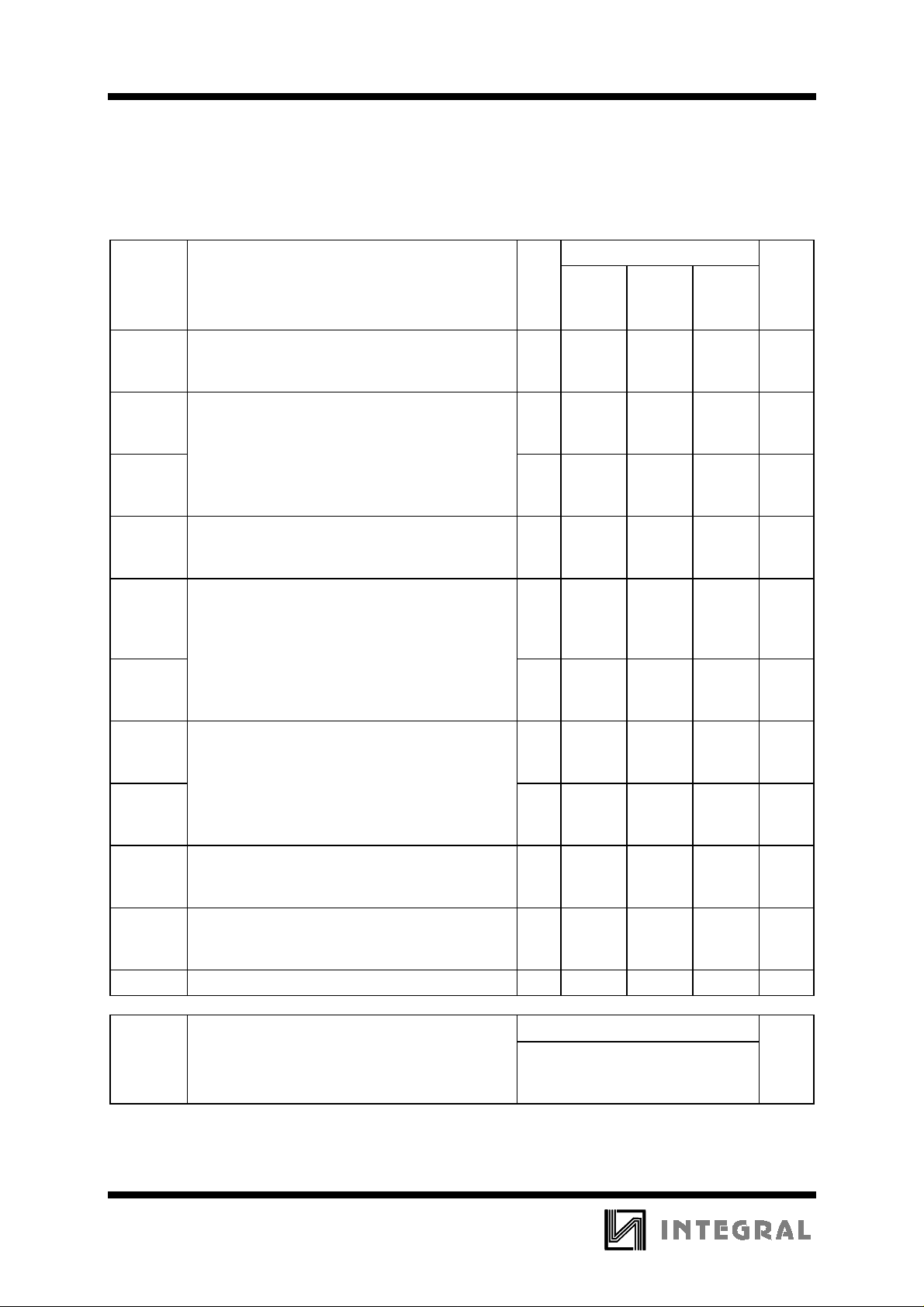
AC ELECTRICAL CHARACTERISTICS
(CL=50pF,Input tr=tf=6.0 ns)
Symbol Parameter V
f
t
max
PLH
Maximum Clock Frequency (Figur es 1,6) 2.0
Maximum Propagati on Delay Clock to Q
t
t
PHL
PHL
(Figures 1,6) 2.0
Maximum Propagation Delay Reset to Q
(Figures 2 and 6)
t
PLH
Maximum Propagation Delay Enable T to Ripple
Carry Out
t
t
PHL
PLH
(Figures 3,6) 2.0
Maximum Propagation Delay Clock to Ripple
t
t
PHL
PHL
Carry Out (Figures 1,6) 2.0
Maximum Propagation Delay Reset to Ripple
Carry Out (Figures 2,6)
t
TLH
, t
Maximum Output Transition Time, Any Output
THL
(Figures 1 and 6)
C
IN
Maximum Input Capacitance - 10 10 10 pF
V
4.5
6.0
2.0
4.5
6.0
4.5
6.0
2.0
4.5
6.0
2.0
4.5
6.0
4.5
6.0
2.0
4.5
6.0
4.5
6.0
2.0
4.5
6.0
2.0
4.5
6.0
CC
Guaranteed Limit
25 °C
≤85°
to
-55°C
6
30
35
120
20
16
145
22
18
145
20
17
110
16
14
135
18
15
120
22
18
145
22
20
155
22
18
75
15
13
C≤125°C
5
24
28
160
23
20
185
25
20
185
22
19
150
18
15
175
20
16
160
27
22
185
28
24
190
26
22
95
19
16
4
20
24
200
28
22
320
30
23
220
25
21
190
20
17
210
22
20
200
30
25
220
35
28
230
30
25
110
22
19
Unit
MHz
ns
ns
ns
ns
ns
ns
ns
ns
ns
200
Power Dissipation Capacitance (Per Gate)
C
PD
Used to determine the no-load dynamic power
consumption:
P
D=CPDVCC
2
f+ICCV
CC
Typical @25°C,V
30 pF
=5.0 V
CC
Page 5
IN74HC161A
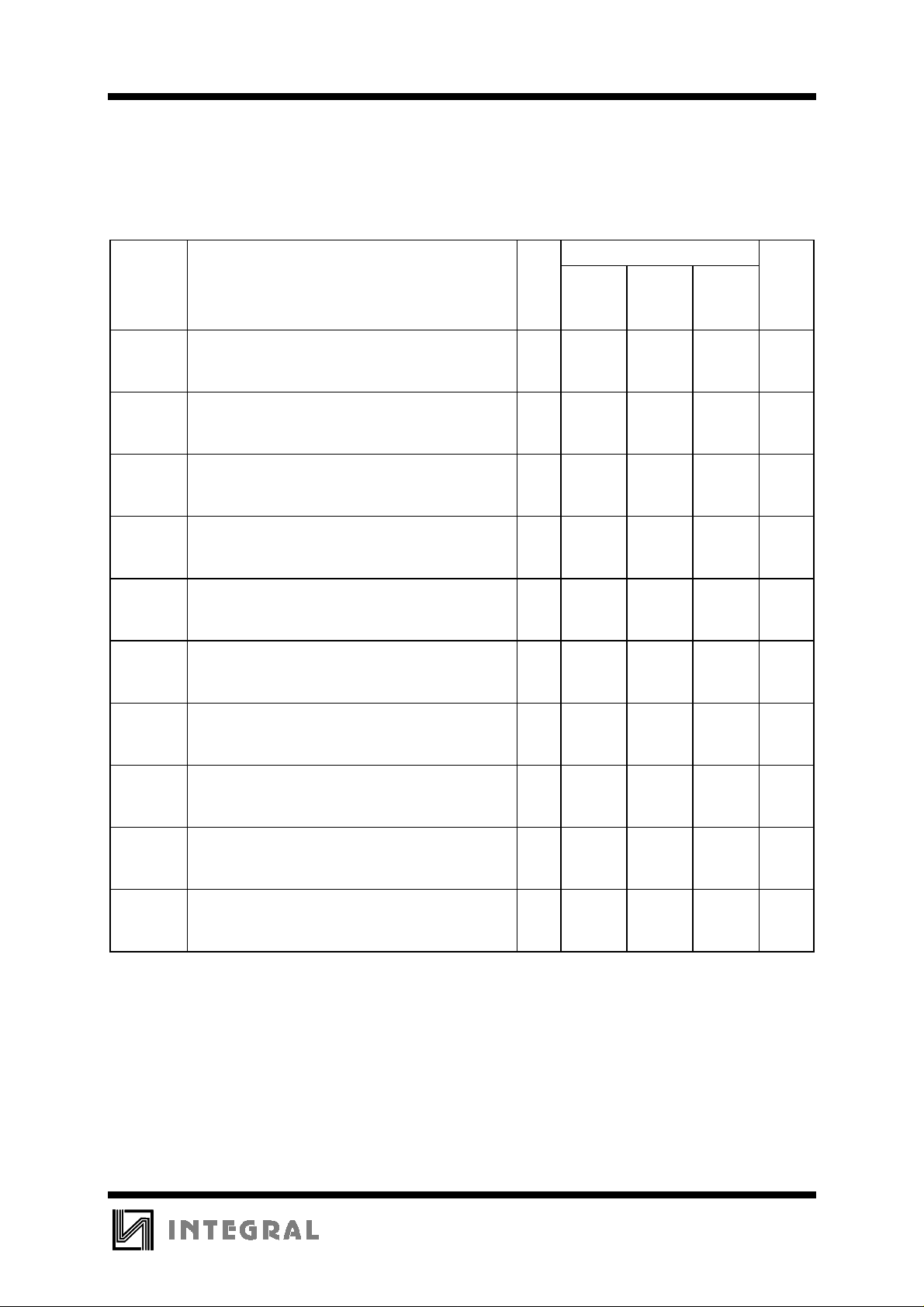
TIMING REQUIREMENTS
(CL=50pF,Input tr=tf=6.0 ns)
Symbol Parameter V
t
SU
Minimum Setup Time, Preset Data Inputs to
Clock (Figure 4)
t
SU
Minimum Setup Time, Load to C lock
(Figure 4)
t
SU
Minimum Setup Time, Enable T or Enable P to
Clock (Figure 5)
t
h
Minimum Hold T ime, Cloc k to Load or Preset
Data Inputs (Figure 4)
t
h
Minimum Hold T ime, Cloc k to Enable T or
Enable P (Figure 5)
t
rec
Minimum Recovery Time, Reset Inactive to Clock
(Figure 2)
t
rec
Minimum Recovery Time, Load Inactive to Clock
(Figure 4)
t
w
t
w
t
r, tf
Minimum Pulse Width, Clock (Figure 1) 2.0
Minimum Pulse Width, Reset (Figure 2) 2.0
Maximum Input Rise and Fall Times
(Figure 1)
V
2.0
4.5
6.0
2.0
4.5
6.0
2.0
4.5
6.0
2.0
4.5
6.0
2.0
4.5
6.0
2.0
4.5
6.0
2.0
4.5
6.0
4.5
6.0
4.5
6.0
2.0
4.5
6.0
CC
Guaranteed Limit
25 °C
≤85°
to
-55°C
40
15
12
60
15
12
80
20
17
3
3
3
3
3
3
80
15
12
80
15
12
60
12
10
60
12
10
1000
500
400
C≤125°C
60
20
18
75
20
18
95
25
23
3
3
3
3
3
3
95
20
17
95
20
17
75
15
13
75
15
13
1000
500
400
80
30
20
90
30
20
110
35
25
3
3
3
3
3
3
110
26
23
110
26
23
90
18
15
90
18
15
1000
500
400
Unit
ns
ns
ns
ns
ns
ns
ns
ns
ns
ns
201
Page 6
IN74HC161A
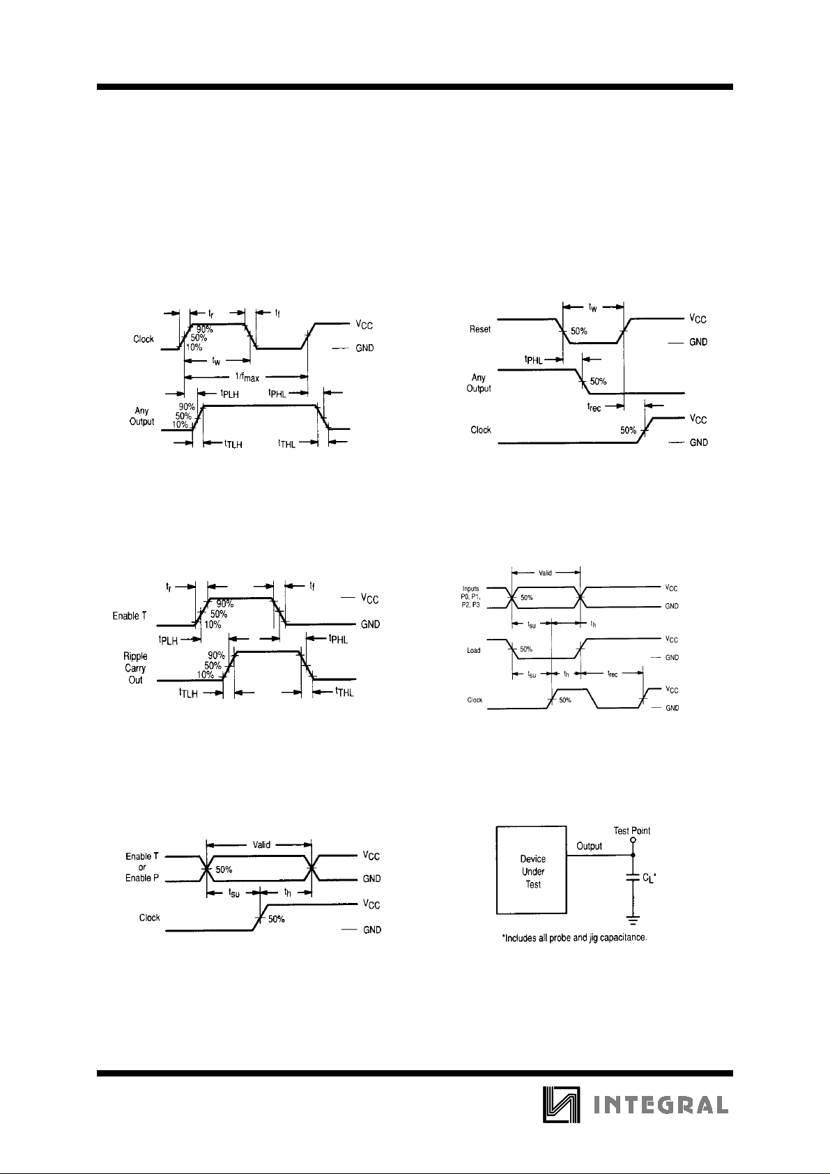
Figure 1. Switching Waveforms Figure 2. Switching Waveforms
202
Figure 3. Switching Waveforms Figure 4. Switching Waveforms
Figure 5. Switching Waveforms Figure 6. Test Circuit
Page 7
IN74HC161A
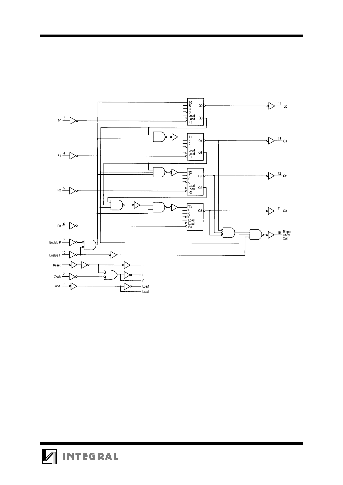
VCC=Pin 16
GND=Pin 8
The flip-flops shown in the circuit diagrams are Toggle-Enable flip-flops. A Toggle-Enable flip-flop is a
combination of a D flip-flop and a T flip-flop. When loading data from Preset inputs P0, P1, P2, and P3, the
Load signal is used to disable the Toggle input (Tn) of the flip-flop. The logic level at the Pn input is then
clocked to the Q output of the flip-flop on the next rising edge of the clock.
A logic zero on the Reset device input forces the internal clock (C) high and resets the Q output of the
flip-flop low.
Figure 7.Expanded logic diagram
203
Page 8
IN74HC161A
204
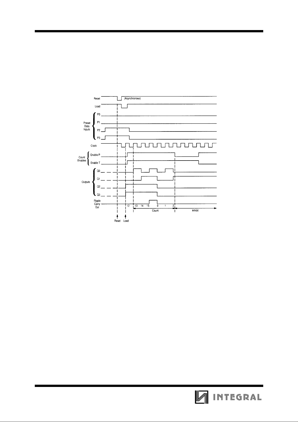
Sequence illustrated in waveforms:
1. Reset outputs to zero.
2. Preset to binary twelve.
3. Count to thirteen, fourteen, fifteen, zero, one, and two.
4. Inhibit.
Figure 8. Timing Diagram
Page 9
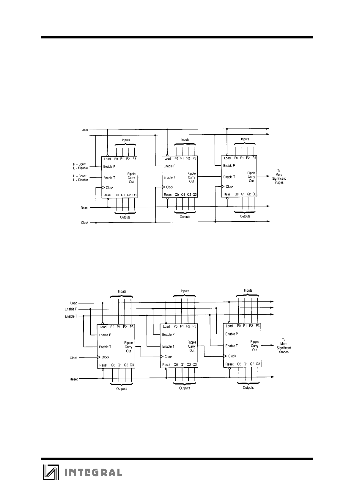
TYPICAL APPLICATIONS CASCADING
IN74HC161A
Note:When used in these cascaded configurations the clock f
Actual performance will depend on number of stages. This limitation is due to set up times
between Enable (Port) and clock.
Figure 9. N-Bit Synchronous Counters
guaranteed limits may not apply.
max
Figure 10. Nibble Ripple Counter
205
 Loading...