

Page 1
TECHNICAL DATA
1
Tone Ringer
The IN2411 is a bipolar integrated circuit designed for telephone bell
replacement.
•
Designed for Telephone Bell Replacement
•
Low Curent Drain
•
Adjustable 2-frequency To ne
•
Adjustable Warbling Rate
•
Extension To ne Ringer Modules
•
Alarms or Other Ale rting Devices
•
Adjustable for Reduced Supply Initiation Current.
•
Built-in hysteresis prevents false triggering and rotary dial ‘Chirps’
IN2411
ORDERING INFORMATION
IN2411N Plastic
TA = -45° to 65° C
for package
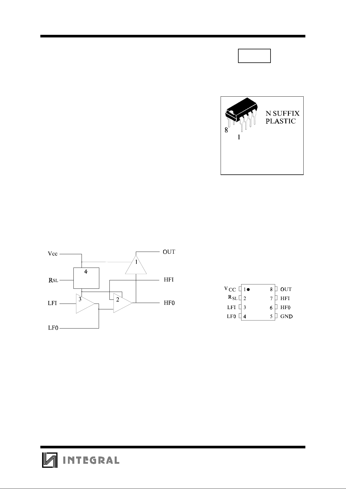
PIN ASSIGNMENT
LOGIC DIAGRAM
PIN 1 = V
CC
PIN 5 = GND
1. Output amplifier
2. High frequency oscillator
3. Low frequency oscillator
4. Hysteresis regulator
(Regulator circuit has built-in hysteresis to prevent false
triggering and rotary dial “Chirps”)
Page 2
IN2411
2
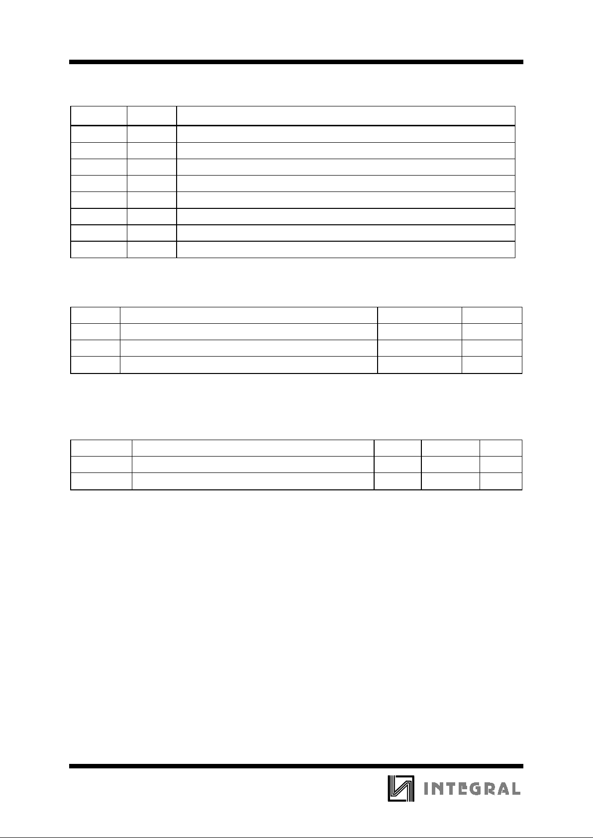
PIN DESCRIPTION
NAME PIN
DESCRIPTION
V
CC
1 Positive power supply.
R
SL
2 External resist or
LFI 3 Input low frequency oscillator
LF0 4 Output low frequency oscillator
GND 5 Negative power supply
HF0 6 High frequency oscillator output
HFI 7 High frequency oscillator input
OUT 8 Tone output
MAXIMUM RATINGS
*
Symbol Parameter Value Unit
V
CC
DC Supply Voltage (Referenced to GND) to +30.0 V
P
D
Power Dissipation in Still Air, Plastic DIP 400 mW
Tstg Storage Temperature -65 to +150
°
C
*
Maximum Ratings are those values beyond which damage to the device may occur.
Functional operation should be restricted to the Recommended Operating Conditions.
RECOMMENDED OPERATING CONDITIONS
Symbol Parameter Min Max Unit
V
CC
DC Supply Voltage (Referenced to GND) 13.0 29.0 V
T
A
Operating Temperature -45 +65
°
C
This device c ontains p rote ction ci rcuitr y to guard a gainst damage d ue to high st atic voltages or electr ic
fields. However, precautions must be taken to avoid applications of any voltage higher than maximum rated
voltages to this high-impedance circuit. For proper operation, V
IN
and V
OUT
should be constrained to the range
GND≤(V
IN
or V
OUT
)≤VCC.
Unused inputs must always be tied to an appropriate logic voltage level (e.g., either GND or V
CC
).
Unused outputs must be left open.
Page 3
IN2411
3
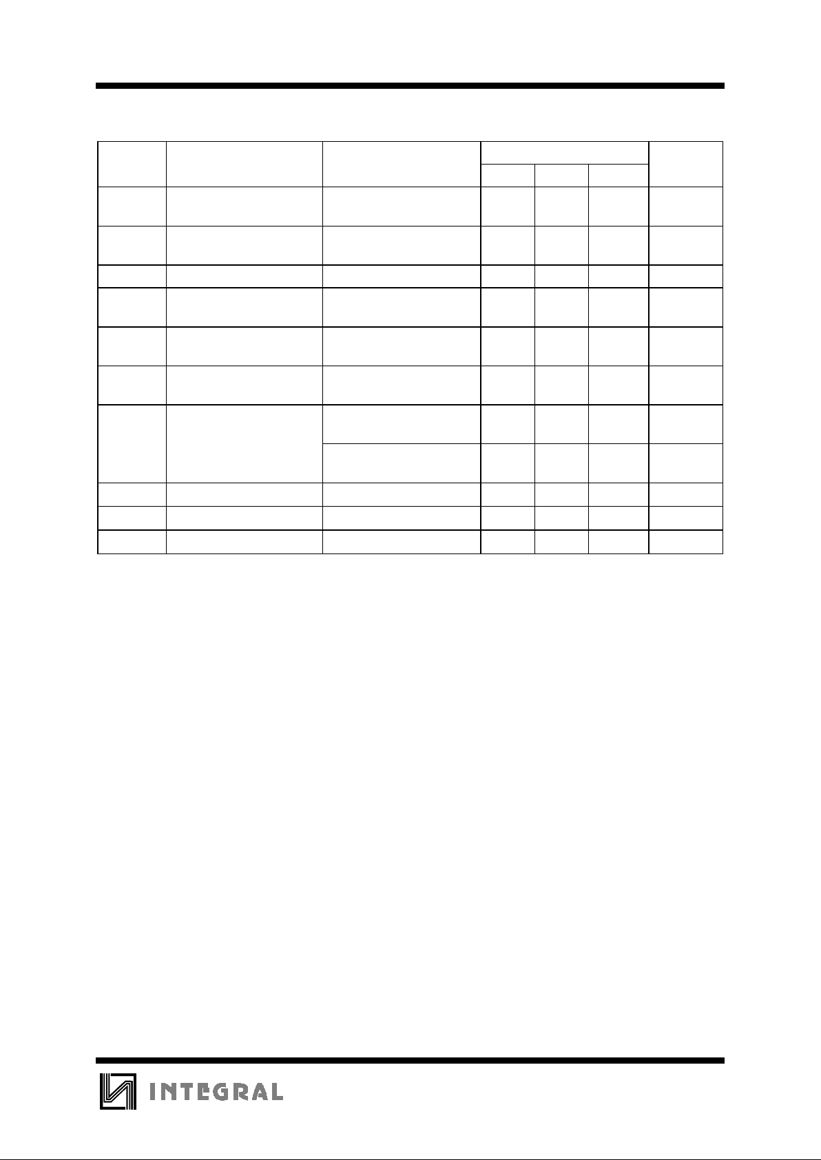
ELECTRICAL CHARACTERISTICS
(Voltages Referenced to GND, TA = -45 to +65°C)
Guaranteed Limits
Symbol Parameter Test Conditions Min Typ Max Unit
V
SI
Initiation Supply Voltage
(1)
See Figure 1 16.8 21.2 V
I
SI
Initiation Supply Current
(1)
1.4 4.2 mA
V
SUS
Sustaining Voltage ( 2) See Figure 1 9.5 12.2 V
I
SUS
Sustaining Current (2) No Loa d VCC=V
SUS
See Figure 1
0.7 2.5 mA
V
OH
High-Level Output
Voltage
VCC=21V, IOH=-15mA,
Pin 6=6V, Pin 7=GND
16.7 21.0 V
V
OL
Low-Level Output
Voltage
VCC=21V, IOL=15mA,
Pin 6=GND, Pin 7=6V
-1.8V
I
IN
Maximun Input Leakage
Current (Pin 3)
Pin 3=6V,Pin 4=GND,
V
CC
=21V
-1.0
µ
A
(Pin 7) Pin 7=6V,Pin 6=GND,
V
CC
=21V
-1.0
µ
A
f
H1
High Frequency 1
R
3
=191KΩ,C3=6800pF
461 563 Hz
f
H2
High Frequency 2
R
3
=191KΩ,C3=6800pF
576 704 Hz
f
L
Low Frequency
R
2
=165KΩ,C2=0.47µF
9.0 11.0 Hz
Notes:
1. Initiation supply voltage (V
SI
) is the supply voltage required to start the tone ringer oscillating.
2. Sustaining voltage (V
SUS
) is the supply voltage required to maintain oscillation.
Page 4
IN2411
4
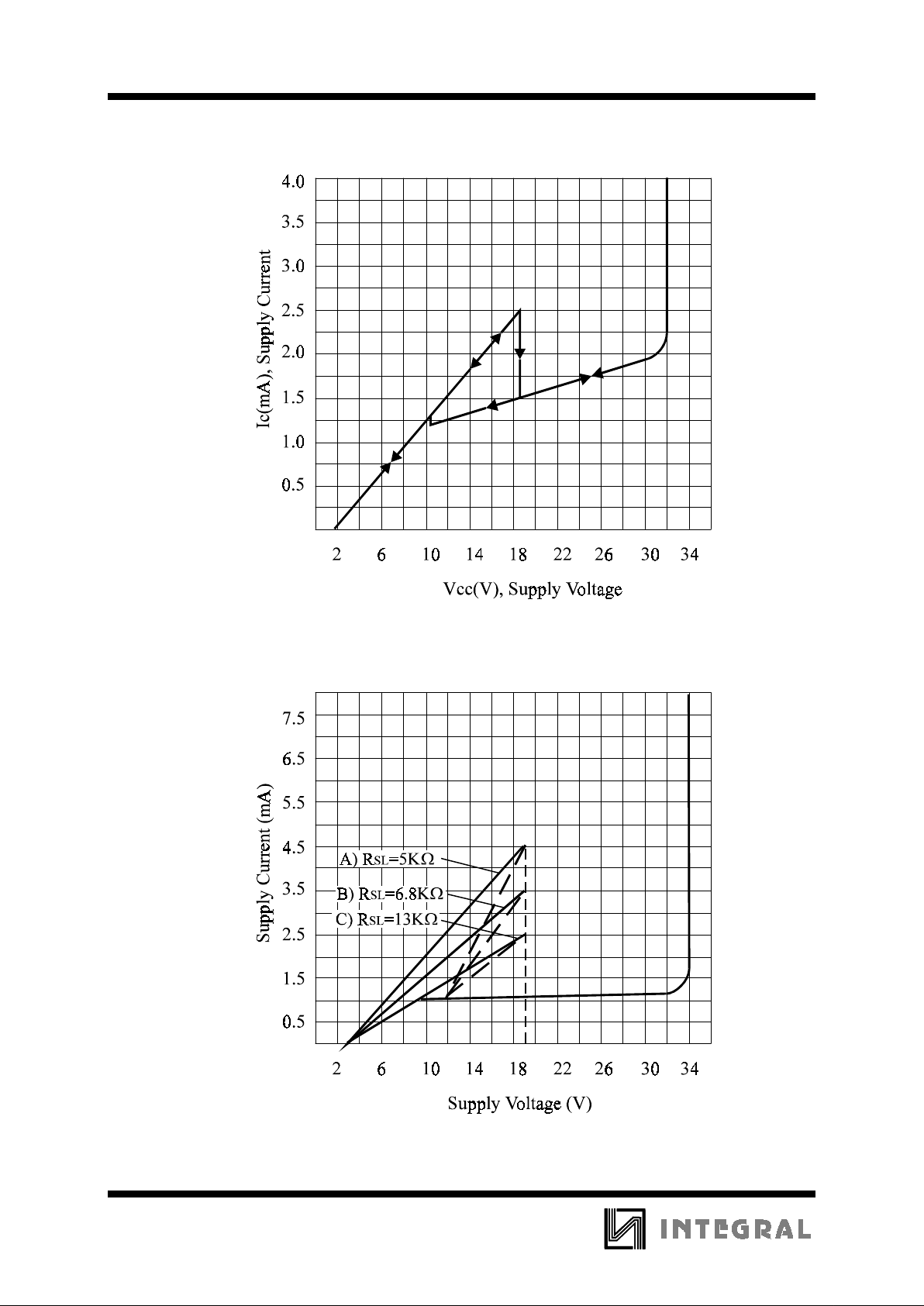
CIRCUIT CURRENT-SUPPLY VOLTAGE (NO LOAD)
Figure 1
SUPPLY CURRENT (NO LOAD) vs. SUPPLY VOLTAGE
Figure 2
Page 5
IN2411
5
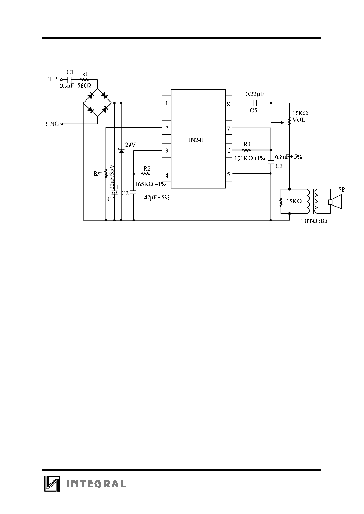
APPLICATION CIRCUIT
Figure 3
Page 6

IN2411
6
APPLICATION NOTE
The application circuit illustrates the use of the IN2411 devices in typical telephone or extension tone ringer
application.
The AC ringer signal voltage appears across the TIP and RING inputs of the circuit and is attenuated by
capacitor C
1
and resistor R1.
C
1
also provides isolation from DC voltages (48V) on the exchange line.
After full wave rectification by the bridge diode, the waveform is filtered by capacitor C
4
to provide a DC supply
for the tone ringer chip.
As this voltage exceeds the initiation voltage (V
SI
), oscillation starts.
With the components shown, the ouptut frequency chops between 512(f
h1
) and 640Hz(fh2) at a 10Hz(fL) rate.
The loudsp eaker load is coupled thro ugh a 1300Ω to 8Ω transformer.
The output coupling capacitor C
5
is required with transformer coupled loads.
When driving a piezo-ceramic transducer type load, the coupling C
5
and transformer (1300Ω:8Ω) are not
required.
However, a current limiting resistor is required.
The low frequency oscillator oscillates at a rate (f
L
) controlled by an external resistor (R2) and capacitor (C2).
The frequency can be determined using the relation f
L
=1/1.289R2xC2. The high frequency oscillates at a fH1, f
H2
controlled by an external resistor (R3) and capacitor (C3). The frequency can be determined using the relation
f
H1
=1/1.504R3xC3, fH2=1/1.203R3xC3.
Pin 2 allows connection of an external resistor R
SL
, which is used to program the solpe of the supply current vs
supply voltage characteristics (see Fig2), and hence the supply current up to the initiation voltage ( V
SI
). This
initiation voltage remains constant independent of R
SL
.
The supply current drawn prior to triggering va ries inversely with R
SL
, decreasing for increasing value of
resistance. Thus, increasing the value of R
SL
will decrease the amount of AC ringing current required to trigger
the device. As such, longer sucribser loops are possible since less voltage is dropped per unit length of loop wire
due to the lower current level. R
SL
can also be used to compensated for smaller AC couplin capacitors (C5 on Fig
3) (higher impe dance) to the line which can be used to alter the ringer equivalence number of a tone r i nger
circuit.
The graph in Fig2 illustrates the variation of supply current with supply voltage. Three curves are drawn to show
the variation of initiation current with R
SL
. Curve B( RSL=6.8KΩ) shows the I-V characteristic for the IN2411
tone ringer.
Curve A is a plot with R
SL
<6.8KΩ and shows an increase in the current drawn up to the initiation voltageVSI. The
I-V characteristic after initiation remains unchanged. Curve C illustrates the effect of increasing R
SL
above
6.8KΩ initiation current decreases but again current after triggering is unchanged.
 Loading...