

Page 1

www.fairchildsemi.com
ILC7083/ILC7084
150mA SOT-23 Low Noise CMOS RF-LDO™
Regulator
Features
• Ultra low 1mV dropout per 1mA load
• 3% output voltage accuracy
• Only 40µV
• Uses low ESR ceramic output capacitor to minimize noise
and output ripple
• Only 100µA ground current at 100mA load
• Ripple rejection up to 85dB at 1kHz, 60dB at 1MHz
• Excellent line and load transient response
• Over current / over temperature protection
• Guaranteed to 150mA output current
• Industry standard five lead SOT-23 package
• Fixed 2.5V, 2.7V, 2.85V, 3.0V, 3.3V, 3.6V, 5V output
voltage for ILC7083 and adjustable output voltage for
ILC7083/ILC7084
• Metal mask option available for custom voltages between
2.5V and 5.1V
RMS
noise
Applications
• Cellular phones
• Wireless communicators
• PDAs / palmtops / organizers
• Battery powered portable electronics
Description
The ILC7083/ILC7084 is a 150mA low dropout (LDO)
voltage regulator designed to provide a high performance
solution to low power systems. The device offers a typical
combination of low dropout and low quiescent current
expected of CMOS parts, while uniquely providing the low
noise and high ripple rejection characteristics usually only
associated with bipolar LDO regulators.
The device has been optimized to meet the needs of modern
wireless communications design; Low noise, low dropout,
small size, high peak current, high noise immunity.
The ILC7083/ILC7084 is designed to make use of low cost
ceramic capacitors while outperforming other devices that
require tantalum capacitors.
As opposed to ILC7084, the ILC7083 has a built in output
capacitor discharge circuit active in shutdown mode. This
feature is necessary in applications where the output voltage
must decrease quickly to zero volt in shutdown mode.
Typical Applications
V
OUT
C
OUT
V
IN
C
IN
54
SOT-23-5
C
ILC7083
12
3
NOISE
ON
OFF
REV. 1.0.9 1/28/03
Page 2

ILC7083/ILC7084
Pin Assignments
Fixed Voltage Option
GND
1
ON/OFF
V
V
IN
IN
2
ILC7083-xx
3
4
SOIC-8
Pin Description ILC7083-xx
C
8
NOISE
N/C
7
V
6
OUT
V
5
OUT
V
OUT
5 4
ILC7083-xx
1
2 3
VINGND
SOT-23-5
C
NOISE
ON/OFF
(Fixed voltage version)
Pin Number
Pin Name Pin DescriptionSOIC-8 SOT-23-5
3 and 4 1 V
IN
Connect directly to supply
1 2 GND Ground pin. Local ground for C
2 3 ON/OFF
84C
NOISE
By applying less than 0.6V to this pin the device will be turned off.
Optional noise bypass capacitor may be connected between this pin and
GND. Do not connect C
5 and 6 5 V
OUT
Output Voltage. Connect C
7 – N/C Not Connected
Adjustable Voltage Option
1
V
OUT
5 4
ILC7083ADJ
or ILC7084ADJ
1 2 3
VINGND
SOT-23-5
V
ADJ
ON/OFF
GND
ON/OFF
V
V
2
3
IN
4
IN
and C
NOISE
directly to the main power ground plane.
NOISE
between this pin and GND.
OUT
OUT
.
ILC7083ADJ
SOIC-8
V
8
ADJ
N/C
7
V
6
OUT
V
5
OUT
Pin Description ILC7083-ADJ
(Adjustable voltage version)
Pin Number
Pin Name Pin DescriptionSOIC-8 SOT-23-5
3 and 4 1 V
IN
Connect directly to supply
1 2 GND Ground pin. Local ground for C
2 3 ON/OFF
84V
ADJ
By applying less than 0.6V to this pin the device will be turned off.
Voltage feedback pin to set the adjustable output voltage. Do not connect a
capacitor to this pin.
5 and 6 5 V
OUT
Output Voltage. Connect C
7 – N/C Not Connected
and C
NOISE
between this pin and GND.
OUT
OUT
.
2
REV. 1.0.9 1/28/03
Page 3

Internal Block Diagram
ILC7083/ILC7084
V
IN
C
NOISE
BANDGAP
REFERENCE
V
REFD
AMPLIFIER
GND
ON/OFF
Absolute Maximum Ratings
Parameter Symbol Ratings Units
Input Voltage
Input Voltage
On/Off
Output Current I
Output Voltage V
Package Power Dissipation (SOT-23-5) P
Maximum Junction Temp Range T
Storage Temperature T
Package Thermal Resistance
ERROR
V
V
ON/OFF
OUT
J(max)
θ
IN
OUT
D
STG
JA
INTERNAL V
FEEDBACK
DD
TRANS-
CONDUCTANCE
AMPLIFIER
V
OUT
-0.3 to +13.5
-0.3 to V
IN
Short circuit protected mA
-0.3 to V
+ 0.3 V
IN
250 (Internally Limited) mW
-40 to +150 °C
-40 to +125 °C
333 °C/W
V
Recommended Operating Conditions
Parameter Min. Typ. Max. Units
Input Voltage V
Operating Ambient Temperature –40 +85 °C
REV. 1.0.9 1/28/03
OUT
+ V
DO
V
+ 1 13 V
OUT
3
Page 4

2
ILC7083/ILC7084
-4
+4
∆
* ∆
2
35
Electrical Characteristics ILC7083/ILC7084
Unless otherwise specified, all limits are at T
Boldface type denotes specifications which apply over the specified operating temperature range.
Parameter Symbol Conditions Min Typ Max Units
Input Voltage Range V
Output Voltage V
Feedback Voltage
V
(ADJ version)
Line Regulation
Dropout Voltage
(V
V
OUT
– V
V
IN
(Note 3)
Ground Pin Current I
Shutdown (OFF) Current I
ON/OFF
ON/OFF
Input Voltage V
Pin Input
GND
ON/OFF
ON/OFF
I
IN( ON/OFF)
Current
Peak Output Current
I
OUT(peak)
(Note 4)
Output Noise Voltage (RMS) eN BW = 300Hz to 50kHz, C
Ripple Rejection
Dynamic Line Regulation
Dynamic Load Regulation ∆V
V
OUT
V
OUT(line)
OUT(load)IOUT
Short Circuit Current I
Notes:
1. Absolute maximum ratings indicate limits which when exceeded may result in damage to the component. Electrical specifications do not apply
when operating the device outside of its rated operating conditions.
2. Specified Min/Max limits are production tested or guaranteed through correlation based on statistical control methods.
Measurements are taken at constant junction temperature as close to ambient as possible using low duty pulse testing.
3. Dropout voltage is defined as the input to output differential voltage at which the output voltage drops 2% below the nominal value measured
with an IV differential.
4. Guaranteed by design.
IN
OUT
ADJ
OUT
SC
=25°C; V
A
1mA < I
1mA <
/
V
V
OUT
OUT(NOM)
)
IN
I
OUT
I
OUT
I
OUT
I
OUT
I
OUT
I
OUT
I
OUT
I
OUT
I
OUT
I
OUT
V
ON/OFF
High = Regulator On
Low = Regulator Off
V
ON/OFF
V
ON/OFF
V
OUT
tpw = 2ms
C
NOISE
I
OUT
V
C
IN
OUT
I
OUT
V
IN
V
OUT(NOM)
tr/tf = 2µs; I
V
OUT
IN
= V
OUT(NOM)
+1V, I
= 1mA, C
OUT
OUT
= 1µF, V
ON/OFF
= 2V.
213
< 150mA -3 V
OUT
I
150mA
<
OUT
V
+1V <
12V 0.007 0.014
<
IN
1.217
1.204
OUT(NOM)
V
OUT(NOM)
1.255 1.292
+3 %V
(NOM)
1.305
0.032
= 0mA (Note 4) 0.1 1
= 10mA 10 25
= 50mA 50 75
100
= 100mA 100 150
200
= 150mA 150 225
300
= 0mA 95 200
220
= 10mA 100 220
240
= 50mA 100 220
240
= 100mA 100 240
260
= 150mA 115 260
280
= 0V 0.1
1.5
0.6
= 0.6V, regulator OFF
= 2V, regulator ON
0.95V
>
OUT(NOM)
= 0.01µF, C
,
OUT
= 1µF
IN
= 2.2µF,
400 500 mA
0.3
1
40 µV
= 10mA
= 4.7µF,
= 100mA
Freq. = 1kHz 85 dB
Freq. = 10kHz 70
Freq. = 1MHz 60
: V
OUT(NOM)
+ 1V to
14 mV
+ 2V,
= 150mA
OUT
: 1mA to 150mA; tr < 5µS 40 mV
= 0V 600 mA
V
OUT
V
%/V
mV
µA
µA
µA
RMS
∆
/ ∆
∆
4
REV. 1.0.9 1/28/03
Page 5

Operation
The ILC7083/ILC7084 LDO design is based on an advanced
circuit configuration for which patent protection has been
applied. Typically it is very difficult to drive a capacitive output with an amplifier. The output capacitance produces a
pole in the feedback path, which upsets the carefully tailored
dominant pole of the internal amplifier. Traditionally the
pole of the output capacitor has been “eliminated” by reducing the output impedance of the regulator such that the pole
of the output capacitor is moved well beyond the gain bandwidth product of the regulator. In practice, this is difficult to
do and still maintain high frequency operation. Typically the
output impedance of the regulator is not simply resistive,
such that the reactive output impedance interacts with the
reactive impedance of the load resistance and capacitance.
In addition, it is necessary to place the dominant pole of
the circuit at a sufficiently low frequency such that the gain
of the regulator has fallen below unity before any of the
complex interactions between the output and the load occur.
The ILC7083/ILC7084 does not try to eliminate the output
pole, but incorporates it into the stability scheme. The load
and output capacitor forms a pole, which rolls off the gain of
the regulator below unity. In order to do this the output
impedance of the regulator must be high, looking like a
current source. The output stage of the regulator becomes a
transconductance amplifier, which converts a voltage to a
current with a substantial output impedance. The circuit
which drives the transconductance amplifier is the error
amplifier, which compares the regulator output to the band
gap reference and produces an error voltage as the input to
the transconductance amplifier. The error amplifier has a
dominant pole at low frequency and a “zero” which cancels
out the effects of the pole. The zero allows the regulator
to have gain out to the frequency where the output pole
continues to reduce the gain to unity. The configuration of
the poles and zero are shown in Figure 1. Instead of powering the critical circuits from the unregulated input voltage,
the CMOS RF LDO powers the internal circuits such as the
bandgap, the error amplifier and most of the transconductance amplifier from the boot strapped regulated output
voltage of the regulator. This technique offers extremely high
ripple rejection and excellent line transient response.
ILC7083/ILC7084
DOMINANT POLE
85 dB
OUTPUT POLE
GAIN
COMPENSATING
ZERO
UNITY GAIN
FREQUENCY
Figure 1. ILC7083/ILC7084 RF LDO Frequency Response
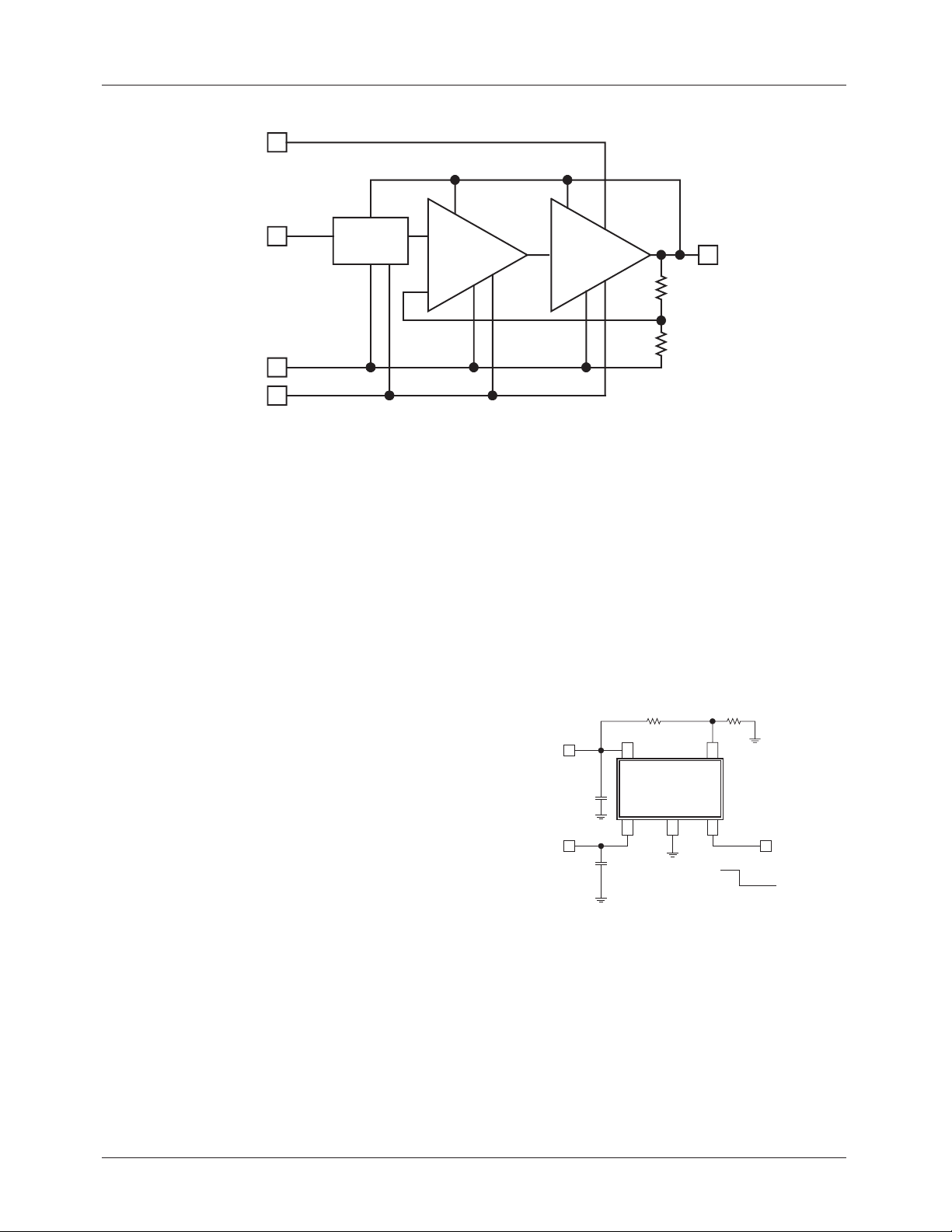
A block diagram of the regulator circuit used in the ILC7083
is shown in Figure 2, which shows the input-to-output isolation and the cascaded sequence of amplifiers that implement
the pole-zero scheme outlined above.
The ILC7083/ILC7084 is designed in a CMOS process with
some minor additions, which allow the circuit to be used at
input voltages up to 13V. The resulting circuit exceeds the
frequency response of traditional bipolar circuits. The
ILC7083/ILC7084 is very tolerant of output load conditions
with the inclusion of both short circuit and thermal overload
protection. The device has a very low dropout voltage,
typically a linear response of 1mV per milliamp of load
current, and none of the quasi-saturation characteristics of a
bipolar output devices. All the good features of the frequency
response and regulation are valid right to the point where the
regulator goes out of regulation in a 4 millivolt transition
region. Because there is no base drive, the regulator is
capable of providing high current surges while remaining in
regulation. This is shown in the high peak current of 500mA
which allows for the ILC7083/ILC7084 to be used in
systems that require short burst mode operation.
REV. 1.0.9 1/28/03 5
Page 6
ILC7083/ILC7084
V
IN
C
NOISE
BANDGAP
REFERENCE
V
REFD
ERROR
AMPLIFIER
GND
ON/OFF
Figure 2. ILC7083 RF LDO Regulator Block Diagram
Shutdown (ON/OFF) Operation
The ILC7083/ILC7084 output can be turned off by applying
0.6V or less to the device’s ON/OFF pin (pin 3). In shutdown
mode, the ILC7083/ILC7084 draws less than 1µA quiescent
current. In shutdown mode the output of ILC7083 is coupled
to a low impedance circuit which discharges the output
capacitor. The output of the ILC7083/ILC7084 is enabled by
applying 1.5V to 13V at the ON/OFF pin. In applications
where the ILC7083 output will always remain enabled, the
ON/OFF pin may be connected to VIN (pin 1). The ILC7083/
ILC7084’s shutdown circuitry includes hysteresis, as such
the device will operate properly even if a slow moving signal
is applied to the ON/OFF pin.
Short Circuit Protection
The ILC7083/ILC7084 output can withstand momentary
short circuit to ground. Moreover, the regulator can deliver
very high output peak current due to its 1A instantaneous
short circuit current capability.
Thermal Protection
The ILC7083/ILC7084 also includes a thermal protection
circuit which shuts down the regulator when die temperature
exceeds 150°C due to overheating. In thermal shutdown,
once the die temperature cools to below 140°C, the regulator
is enabled. If the die temperature is excessive due to high
package power dissipation, the regulator’s thermal circuit
will continue to pulse the regulator on and off. This is called
thermal cycling.
Excessively high die temperature may occur due to high differential voltage across the regulator or high load current or
high ambient temperature or a combination of all three.
Thermal protection protects the regulator from such fault
conditions and is a necessary requirement in today’s designs.
INTERNAL V
FEEDBACK
DD
TRANS-
CONDUCTANCE
AMPLIFIER
V
OUT
In normal operation, the die temperature should be limited to
under 150°C.
Adjustable Output Voltage
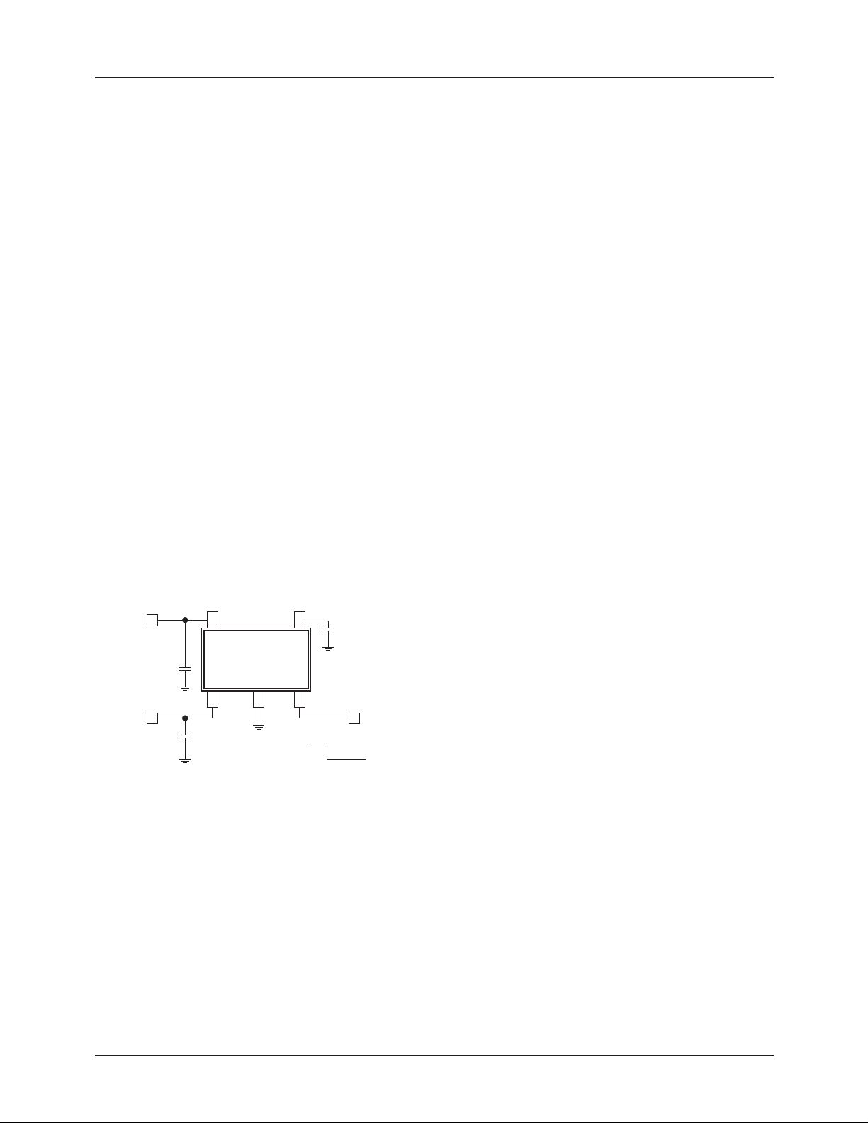
Figure 5 shows how an adjustable output voltage can be easily achieved using ILC7083/ILC7084-ADJ. The output voltage, V
Figure 3. Application Circuit for Adjustable Output Voltage
For best results, a resistor value of 470kΩ or less may be
used for R2. The output voltage can be programmed from
2.5V to 12V.
Note that an external capacitor should not be connected
to the adjustable feedback pin (pin 4). Connecting an
external capacitor to pin 4 may cause regulator instability and lead to oscillations.
is given by the following equation:
OUT
V
= 1.255V x (R1/R2 + 1)
OUT
R1 R2
V
V
OUT
C
IN
OUT
C
IN
SOT23-5
5
ILC7083-ADJ
or ILC7084-ADJ
123
V
ADJ
4
ON
OFF
6 REV. 1.0.9 1/28/03
Page 7
ILC7083/ILC7084
Maximum Output Current
The maximum output current available from the ILC7083/
ILC7084 is limited by the maximum package power dissipation as well as the device’s internal current limit. For a given
ambient temperature, TA, the maximum package power
dissipation is given by:
P
where T
D(MAX)
= (T
J(MAX)
– TA) / θ
J(MAX)
JA
= 150°C is the maximum junction tempera-
ture and θJA = 333°C/W is the package thermal resistance.
For example at TA = 85°C ambient temperature, the maximum package power dissipation is;
P
D(MAX)
= 195mW.
The maximum output current can be calculated from the following equation:
I
OUT(MAX)
For example at VIN = 6V, V
maximum output current is I
< P
D(MAX)
/ (VIN – V
OUT
OUT(MAX)
)
OUT
= 5V and TA = 85°C, the
< 195mA. At higher
output current, the die temperature will rise and cause the
thermal protection circuit to be enabled.
Application Hints
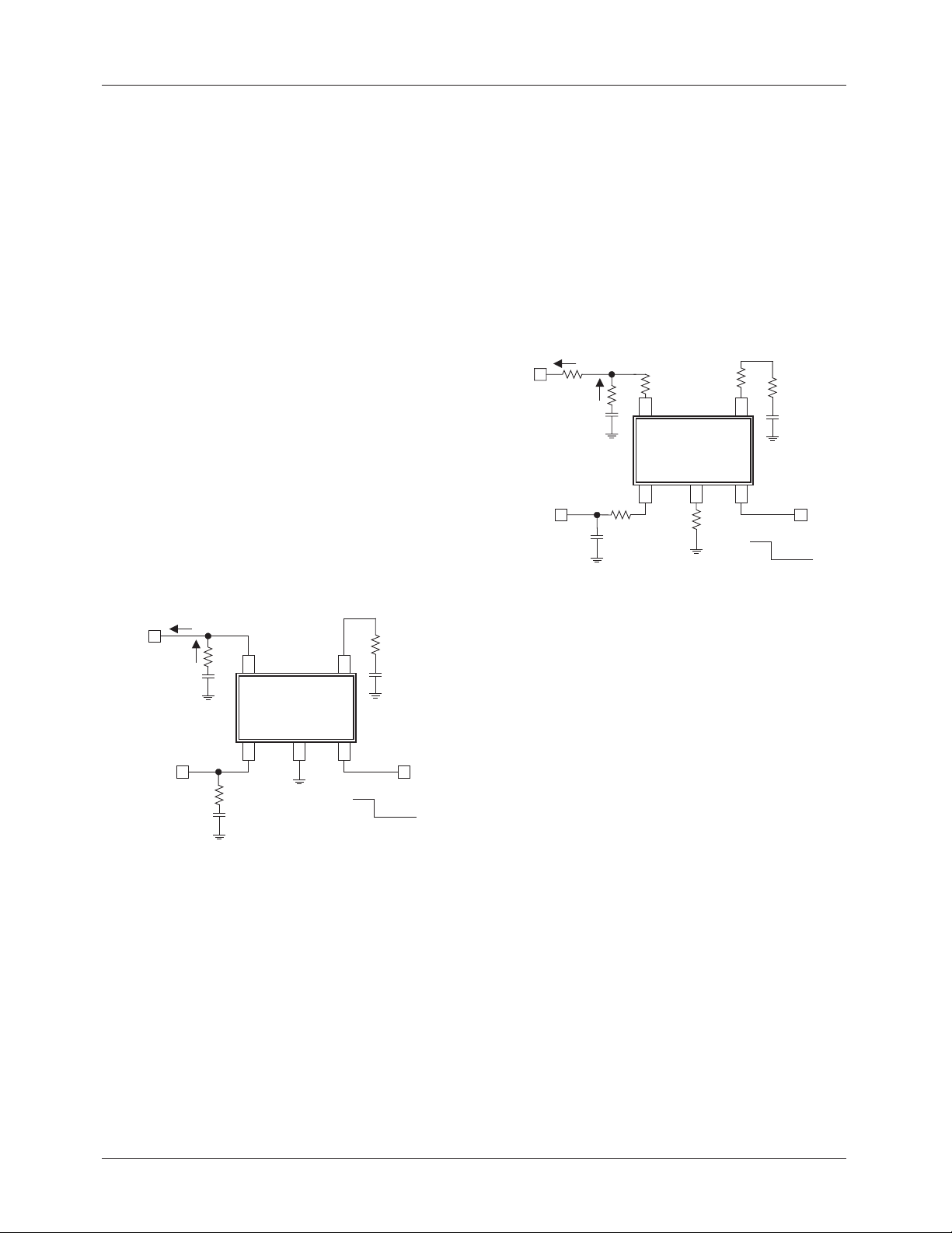
Figure 4 shows the typical application circuit for the
ILC7083.
V
OUT
SOT23-5
45
C
NOISE
the regulator may be damaged. This condition must be
avoided. In many applications a large value input capacitor,
CIN, will hold VIN higher than V
V
when the LDO is powered off.
OUT
and decay slower than
OUT
Output Capacitor Selection
Fairchild strongly recommends the use of low ESR
(equivalent series resistance) ceramic capacitors for C
and C
. The ILC7083/ILC7084 is stable with low ESR
NOISE
capacitor (as low as zero Ω). The value of the output
capacitor should be 1µF or higher. Either ceramic chip or
a tantalum capacitor may be used at the output.
Use of ceramic chip capacitors offer significant advantages
over tantalum capacitors. A ceramic capacitor is typically
cheaper than a tantalum capacitor, it usually has a smaller
footprint, lower height, and lighter weight than a tantalum
capacitor. Furthermore, unlike tantalum capacitors which are
polarized and can be damaged if connected incorrectly,
ceramic capacitors are non-polarized. Low value ceramic
chip capacitors with X5R or X7R dielectric are available in
the 100pF to 4.7µF range. Beware of using ceramic capacitors with Y5V dielectric since their ESR increases significantly at cold temperatures. Please see the table of
recommended ceramic capacitors for use at the output of
ILC7083/ILC7084.
Note: If a tantalum output capacitor is used then for stable
operation. We recommend a low ESR tantalum capacitor
with maximum rated ESR at or below 0.4Ω. Low ESR tantalum capacitors, such as the TPS series from AVX Corporation (www.avxcorp.com) or the T495 series from Kemet
(www.kemet.com) may be used.
OUT
C
OUT
ILC7083
In applications where a high output surge current can be
expected, use a high value but low ESR output capacitor for
V
IN
C
IN
123
ON
OFF
superior load transient response. The ILC7083/ILC7084 is
stable with no load.
Noise Bypass Capacitor
In low noise applications, the self noise of the ILC7083 can
Figure 4. Basic Application Circuit for
Fixed Output Voltage Versions
be decreased further by connecting a capacitor from the
noise bypass pin (pin 4) to ground (pin 2). The noise bypass
pin is a high impedance node as such care should be taken in
Input Capacitor
An input capacitor CIN of value 1µF or larger should be connected from VIN to the main ground plane. This will help to
filter supply noise from entering the LDO. The input capacitor should be connected as close to the LDO regulator input
pin as is practical. Using a high-value input capacitor will
offer superior line transient response as well as better power
supply ripple rejection. A ceramic or tantalum capacitor may
be used at the input of the LDO regulator.
Note that there is a parasitic diode from the LDO regulator
output to the input. If the input voltage swings below the reg-
printed circuit board layout to avoid noise pick-up from
external sources. Moreover, the noise bypass capacitor
should have low leakage.
Noise bypass capacitors with a value as low as 470pF may
be used. However, for optimum performance, use a 0.01µF
or larger, ceramic chip capacitor. Note that the turn on and
turn off response of the ILC7083 is inversely proportional to
the value of the noise bypass capacitor. For fast turn on and
turn off, use a small value noise bypass capacitor. In applications where exceptionally low output noise is not required,
consider omitting the noise bypass capacitor altogether.
ulator’s output voltage by a couple of hundred millivolts then
REV. 1.0.9 1/28/03 7
Page 8
ILC7083/ILC7084
The Effects of ESR (Equivalent Series
Resistance)
The ESR of a capacitor is a measure of the resistance due to
the leads and the internal connections of the component.
Typically measured in mΩ (milli-ohms) it can increase to
ohms in some cases.
Wherever there is a combination of resistance and current,
voltages will be present. The control functions of LDOs use
two voltages in order to maintain the output precisely; V
and V
REF
.
With reference to the block diagram in Figure 4, V
back to the error amplifier and is used as the supply voltage
for the internal components of the ILC7083/ILC7084. So
any change in V
compensate to maintain V
V
will be reflected into the supply of each internal
OUT
will cause the error amplifier to try to
OUT
at the set level and noise on
OUT
components of the ILC7083/ILC7084. So any change in
V
will cause the error amplifier to try to compensate to
OUT
maintain V
at the set level and noise on V
OUT
OUT
reflected into the supply of each internal circuit. The reference voltage, V
, is influenced by the C
REF
NOISE
pin. Noise
into this pin will add to the reference voltage and be fed
through the circuit. These factors will not cause a problem if
some simple steps are taken. Figure 5 shows where these
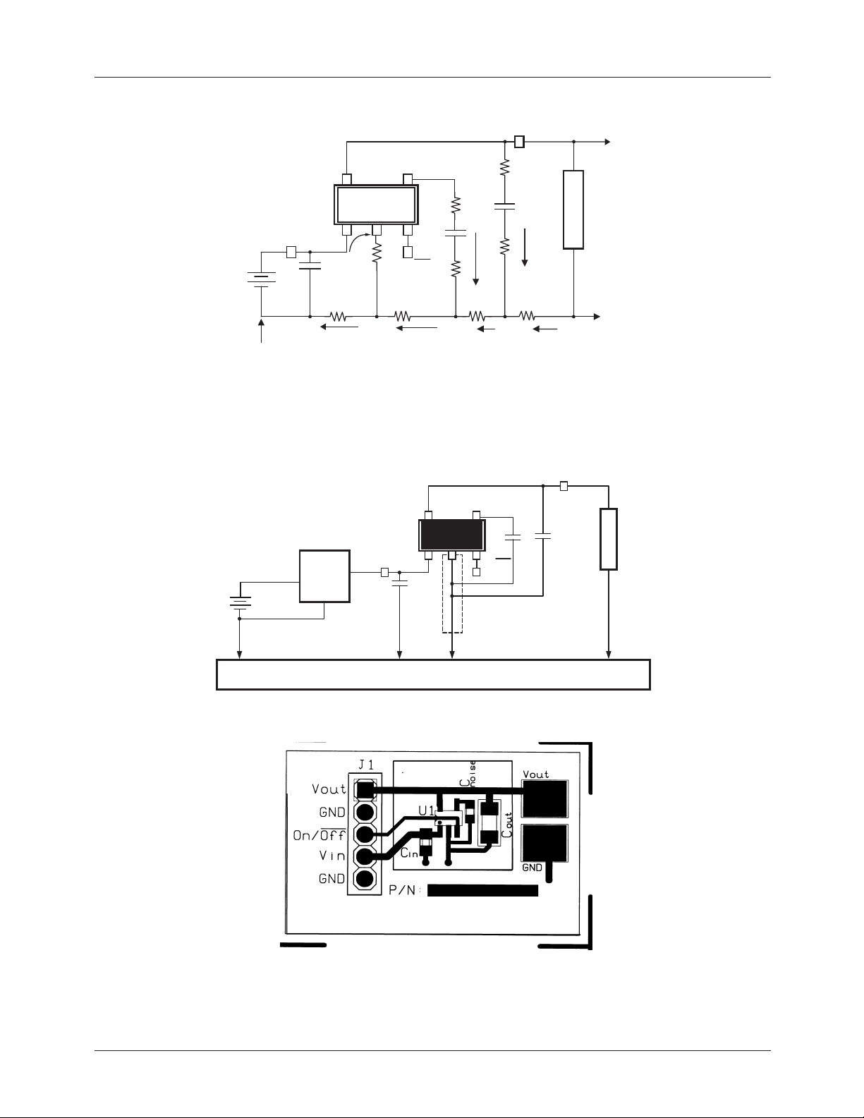
added ESR resistances are present in the typical LDO circuit.
is fed
OUT
will be
OUT
these resistances may be very small, but a summation of
several currents can develop detectable voltage ripple and
will be amplified by the LDO. Particularly the accumulation
of current flows in the ground plane can develop significant
voltages unless care is taken. With a degree of care, the
ILC7083/ILC7084 will yield outstanding performance.
Printed Circuit Board Layout Guidelines
As was mentioned in the previous section, to take full advantage of any high performance LDO regulator requires paying
careful attention to grounding and printed circuit board
(PCB) layout.
I
V
OUT
OUT
I
1
C
OUT
V
IN
C
IN
Figure 6. Inherent PCB resistance
R
PCB
ESR
SOT-23-5
5
ILC7083
123
R
PCB
R
PCB
4
R
PCB
ON
ESR
C
NOISE
OFF
I
V
OUT
OUT
R*
I
R
C
C
SOT-23-5
C
OUT
V
IN
C
Figure 5. ESR Present in C
5
ILC7083
123
R*
IN
RF LDO
Regulator
With this in mind low ESR components will offer better
performance where the LDO may be subjected to large load
transients current. ESR is less of a problem with CIN as the
voltage fluctuations at the input will be filtered by the LDO.
However, being aware of these current flows, there is also
another potential source of induced voltage noise from the
resistance inherent in the PCB trace. Figure 6 shows where
the additive resistance of the PCB can manifest itself. Again
TM
OUT
4
ON
and C
C
NOISE
OFF
NOISE
Figure 7 shows the effects of poor grounding and PCB
layout magnified by the ESR and PCB resistances and
the accumulation of current flows.
Note that particularly during high output load current, the
LDO regulator’s ground pin and the ground return for C
and C
are not at the same potential as the system
NOISE
OUT
ground. This is due to high frequency impedance caused by
PCB’s trace inductance and DC resistance. The current loop
between C
OUT
, C
and the LDO regulator’s ground pin
NOISE
will degrade performance of the LDO.
Figure 8 shows an optimum schematic. In this schematic,
high output surge current has little effect on the ground current and noise bypass current return of the LDO regulator.
Note that the key difference here is that C
OUT
and C
NOISE
are
directly connected to the LDO regulator’s ground pin. The
LDO is then separately connected to the main ground plane
and returned to a single point system ground.
The layout of the LDO and its external components are also
based on some simple rules to minimize EMI and output
voltage ripple.
8 REV. 1.0.9 1/28/03
Page 9
ILC7083/ILC7084
V
OUT
True GND
(0V)
V
BATT
+
5
ILC7083
SOT-23-5
V
IN
I
LOAD
+IC
+IC
GND2
OUT
NOISE
C
IN
4
321
GND
ON/OFF
I
LOAD
+IC
+IC
OUT
NOISE
NOISE
C
GND3
+IGND
Figure 7. Effects of Poor Circuit Layout
ILC7083
SOT-23-5
DC/DC
Converter
GND
V
C
IN
IN
12
Local
Ground
I
+IC
45
3
NOISE
C
GND4
LOAD
OUT
C
ON/OFF
C
NOISE
IC
OUT
OUT
I
LOAD
V
OUT
C
OUT
ESR<0.5
GND5GND1
LOAD
LOAD
Ground Plane
Ground PlaneGround Plane
Ground Plane
Figure 8. Recommended Application Circuit Schematic
Fairchild Semiconductor - Eval. Board
Figure 9. Recommended Application Circuit Layout (not drawn to scale)
Note, ground plane is bottom layer of PCB and connects to top layer ground connections through vias.
REV. 1.0.9 1/28/03 9
Page 10
ILC7083/ILC7084
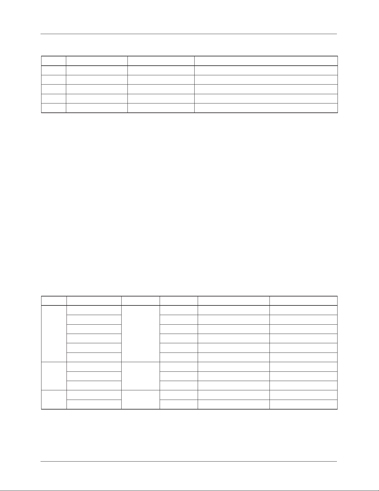
Evaluation Board Parts List (for Figure 9)
Label Part Number Manufacturer Description
U1 ILC7083AIM5-30 Fairchild Semiconductor 150mA RF LDO™ regulator
J1 69190-405 Berg Connector, four position header
Cin GRM40 Y5V 105Z16 muRata Ceramic capacitor, 1µF,16V, SMT (size 0805)
Cnoise ECU-V1H103KBV Panasonic Ceramic capacitor, 0.01µF,16V, SMT (size 0603)
Cout GRM42-6X5R475K10 muRata Ceramic capacitor, 4.7µF,16V, SMT (size 1206)
Grounding Recommendations
1. Connect CIN between VIN of the ILC7083 and the
“GROUND PLANE”.
2. Keep the ground side of C
OUT
and C
the “LOCAL GROUND” and not directly to the
“GROUND PLANE”.
connected to
NOISE
Layout Considerations
1. Place all RF LDO related components; ILC7083, input
capacitor C
capacitor C
2. Keep the output capacitor C
as possible with very short traces to the V
, noise bypass capacitor C
IN
as close together as possible.
OUT
as close to the ILC7083
OUT
NOISE
pins.
3. On multilayer boards use component side copper for
grounding around the ILC7083 and connect back to a
“GROUND PLANE” using vias.
4. If using a DC-DC converter in your design, use a star
3. The traces for the related components; ILC7083, input
capacitor CIN, noise bypass capacitor C
capacitor C
can be run with minimum trace widths
OUT
NOISE
close to the LDO.
grounding system with separate traces for the power
ground and the control signals. The star should radiate
from where the power supply enters the PCB.
4. Maintain a separate “LOCAL GROUND” remote from
the “GROUND PLANE” to ensure a quiet ground near
the LDO.
Figure 9 shows how this circuit can be translated into a PCB
layout.
Recommended Ceramic Output Capacitors
C
OUT
1µF 0805 0 to 150mA X5R C2012X5R1A105KT TDK
2.2µF 0805 0 to 150mA X5R GRM40X5R225K 6.3 muRata
4.7µF 1206 0 to 150mA X5R GRM42-6X5R475K010 muRata
Capacitor Size I
OUT
Dielectric Part Number Capacitor Vendor
0805 X7R GRM40X7R105K010 muRata
0805 X7R LMK212BJ105KG Taiyo-Yuden
1206 X7R GRM42-6X7R105K016 muRata
1206 X7R EMK316BJ105KL Taiyo-Yuden
1206 X5R TMK316BJ105KL Taiyo-Yuden
0805 X5R C2012X5R0J225KT TDK
1206 X5R EMK316BJ225ML Taiyo-Yuden
1206 X7R LMK316BJ475ML Taiyo-Yuden
and output
and GND
OUT
and output
10 REV. 1.0.9 1/28/03
Page 11
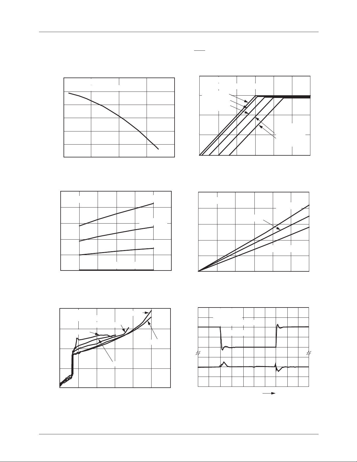
Typical Performance Characteristics ILC7083/ILC7084
ILC7083/ILC7084
Unless otherwise specified: TA = 25°C, VIN = V
Output Voltage vs Temperature
3.015
3.01
3.005
2.995
Output voltage (V)
2.99
2.985
250
200
150
V
= 3.0V
OUT
C
= 1µF (Ceramic)
OUT
3
0 50 100 150-50
Temperature (°C)
Dropout Voltage vs Temperature
V
= 3.0V
OUT
I
OUT
I
OUT
OUT(NOM)
= 150mA
= 100mA
+ 1V, ON/OFF pin tied to V
Dropout Characteristics
3.4
V
= 3.3V
OUT
C
= 1µF (Ceramic)
OUT
I
= 0mA
OUT
I
= 10mA
OUT
I
= 50mA
OUT
3 3.2 3.4 3.6
Dropout Voltage vs I
V
= 3.0V
OUT
(V)
OUT
V
3.3
3.2
3.1
3
250
200
150
IN
I
= 100mA
OUT
I
= 150mA
OUT
V
(V)
IN
OUT
T
= 85°C
A
T
= 25°C
A
100
50
Dropout voltage (mV)
I
0
–40 8525
OUT
I
= 0mA
Temperature (°C)
Ground Current vs Input Voltage
150
V
= 3.0 V
OUT
C
= 1µF (Ceramic)
OUT
125
I
= 150mA
OUT
100
(µA)
GND
I
75
50
2 4 6 8 10 12 14
I
OUT
= 50mA
I
= 100mA
OUT
I
OUT
= 10mA
VIN (V)
OUT
I
OUT
= 50mA
= 0mA
100
T
= –40°C
A
50
Dropout voltage (mV)
0
0 50 100 150
Output Current (mA)
Line Transient Response
(V)V
IN
V
3.01
(V)
3.00
OUT
2.99
2.98
6
5
4
V
: tr/tf < 1 µs
IN
V
= 3.0V
OUT
C
= 2.2 µF (Ceramic)
OUT
I
= 100 mA
OUT
5µs/div
REV. 1.0.9 1/28/03 11
Page 12
ILC7083/ILC7084
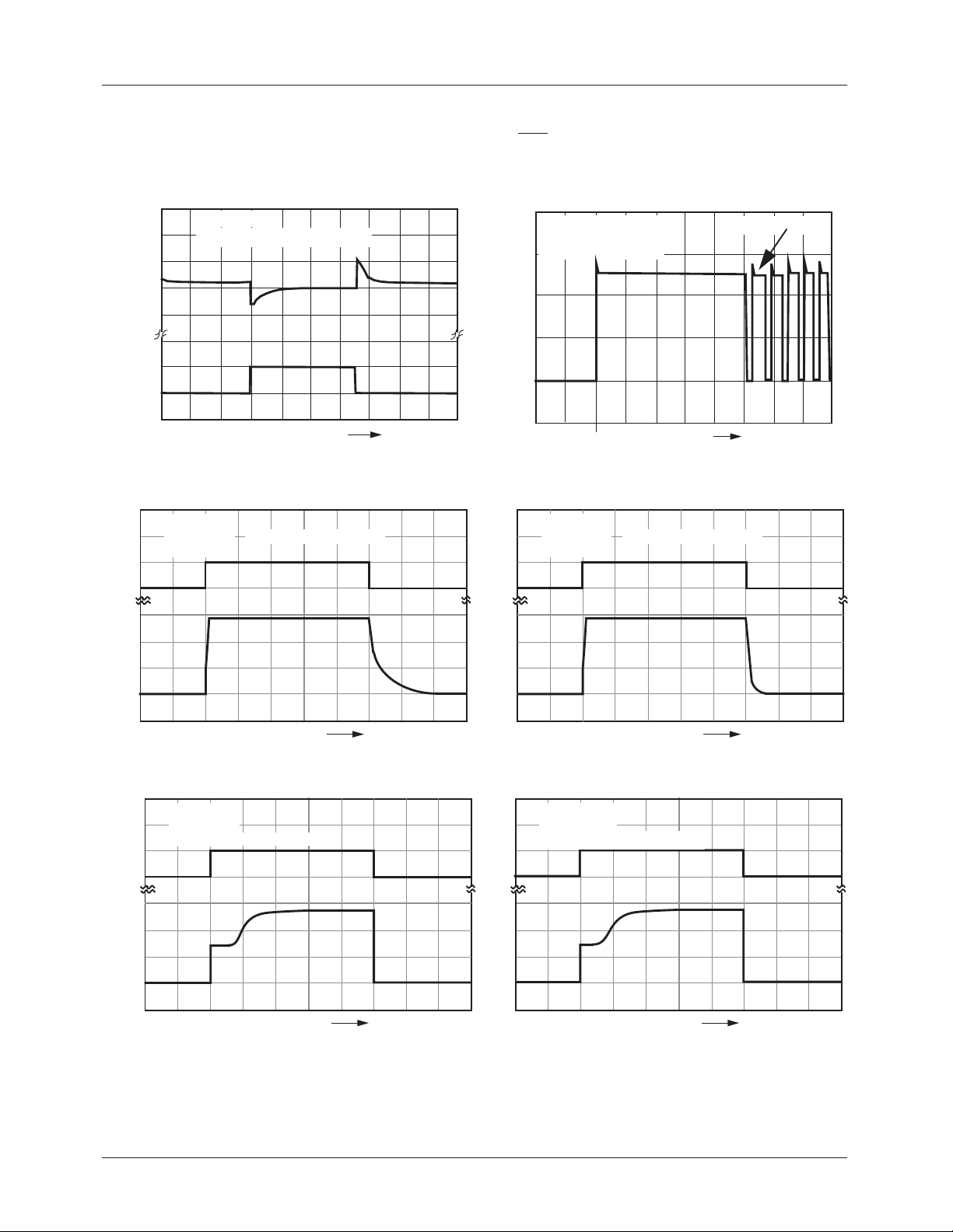
Typical Performance Characteristics ILC7083/ILC7084
Unless otherwise specified: TA = 25°C, VIN = V
OUT(NOM)
+ 1V, ON/OFF pin tied to V
IN
3.15
3.10
(V)I
3.05
OUT
V
3.00
2.95
100
(mA)
OUT
15
(V)
10
5
ON/OFF
V
0
3
2
(V)
1
OUT
V
0
Load Transient Response
V
= 3.0V
OUT
C
= 1 µF || 0.47 µF (Ceramic)
OUT
V
= 4V
IN
Output Shorted to Gnd
at time,
1.5
Short Circuit Current
Thermal Cycling
t = 0
1.0
(A)
SC
I
0.5
15
(V)
10
5
ON/OFF
V
0
3
2
(V)
1
OUT
V
0
0
t = 0
5ms/div
On/Off Transient Response
V
= 2.8V
OUT
= 150mA
C
I
OUT
OUT
= 1µF
Without C
NOISE
Capacitor
1
100µs/div
On/Off Transient Response
V
= 2.8V
OUT
= 10mA
I
C
OUT
OUT
= 1µF
Without C
NOISE
Capacitor
15
(V)
10
5
ON/OFF
V
0
3
2
(V)
1
OUT
V
0
V
I
C
OUT
OUT
NOISE
100µS/div
On/Off Transient Response
= 2.8V
= 10mA
= 0.01µF, C
OUT
= 1µF
5mS/div
15
(V)
10
5
ON/OFF
V
0
3
2
(V)
1
OUT
V
0
C
V
I
OUT
OUT
NOISE
= 2.8V
= 150mA
= 0.01µF, C
100µS/div
On/Off Transient Response
= 1µF
OUT
5mS/div
12 REV. 1.0.9 1/28/03
Page 13
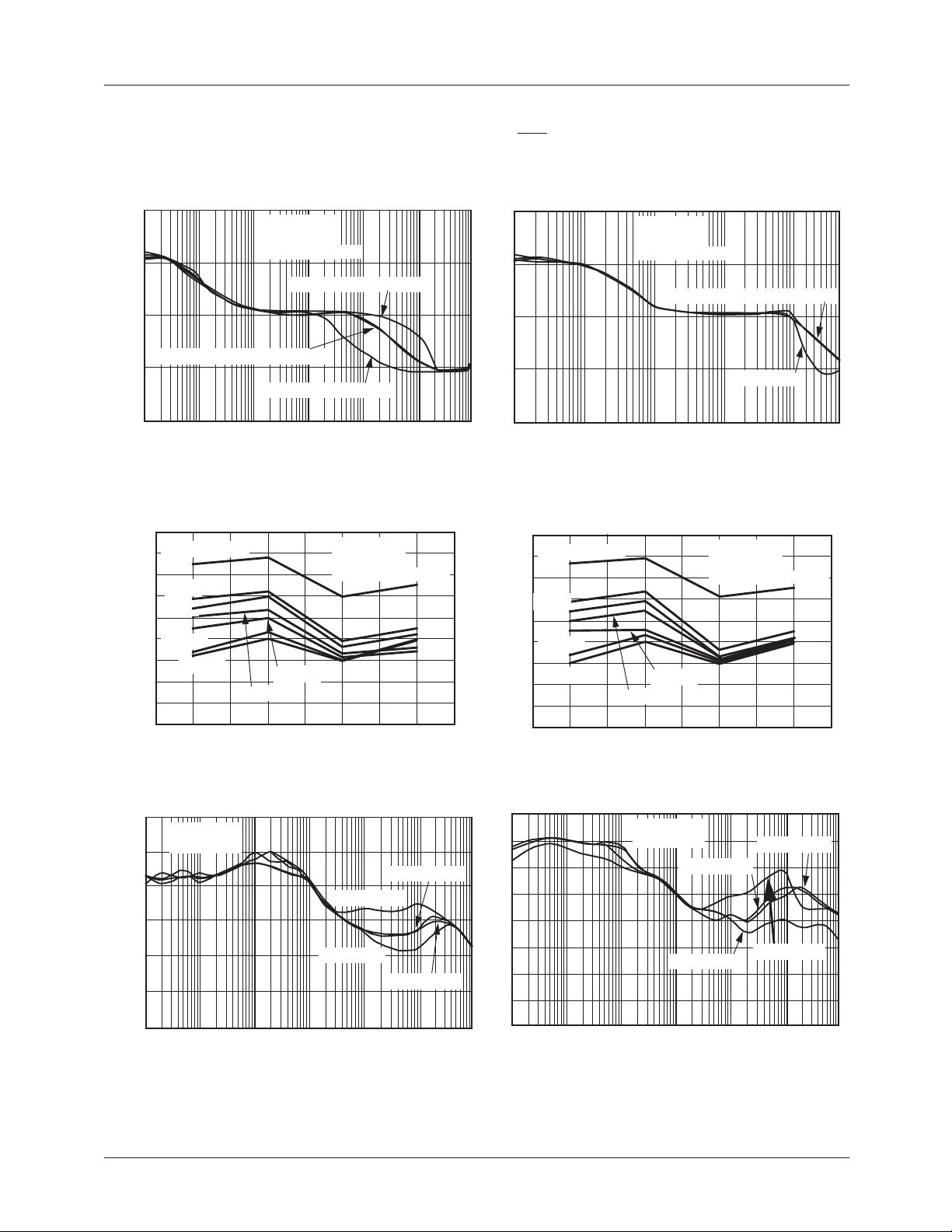
Typical Performance Characteristics ILC7083/ILC7084
Unless otherwise specified: TA = 25°C, VIN = V
OUT(NOM)
+ 1V, ON/OFF pin tied to V
ILC7083/ILC7084
IN
10
1
0.1
C
Noise (µV/Rt Hz)
0.01
= 2.2µF or 4.7µF (Ceramic)
OUT
0.001
Output Noise Voltage vs. C
90
C
= 1.2nF
NOISE
80
70
5.6nF
60
8.2nF
50
40
0.039µF
30
Noise (µVrms)
0.047µF
20
10
0
100 Hz–
50 KHz
Ripple Rejection vs. Frequency
120
100
80
60
40
V
I
OUT
OUT
= 3V
= 10mA
Ripple Rejection (dB)
20
0
Spectral Noise Density
V
= 2.8V
OUT
= 50mA
I
OUT
C
= 0.01µF
NOISE
C
= 1µF (Ceramic)
OUT
C
= 10µF (Ceramic)
OUT
10K 1M1K10010
100K
Frequency (Hz)
V
= 3V
OUT
= 10mA
I
OUT
C
= 2.2µF(Ceramic)
OUT
0.022µF
0.01µF
100 Hz–
100 KHz
300 Hz–
50 KHz
Freq Band
C
= 10µF
OUT
C
= 1µF
OUT
10K 1M1K10010
100K
Frequency (Hz)
NOISE
C
C
300 Hz–
100 KHz
= 4.7µF
OUT
= 2.2µF
OUT
10
1
0.1
Noise (µV/Rt Hz)
0.01
0.001
10M
90
C
80
70
60
5.6nF
8.2nF
50
40
0.039µF
30
Noise (µVrms)
20
10
0
80
70
60
50
40
30
Ripple Rejection (dB)
20
10
0
10M
Spectral Noise Density
V
= 2.8V
OUT
= 2.2µF
C
OUT
C
= 0.01µF
NOISE
I
= 50mA, 100mA or 150 mA
OUT
Frequency (Hz)
Output Noise Voltage vs. C
= 1.2nF
NOISE
0.047µF
0.022µF
0.016µF
100 Hz–
50 KHz
100 Hz–
100 KHz
300 Hz–
50 KHz
Freq Band
Ripple Rejection vs. Frequency
V
= 2.8V
OUT
= 150mA
I
OUT
C
OUT
C
= 1µF
OUT
10K 1M1K10010
Frequency (Hz)
I
OUT
10K 100K1K10010
NOISE
V
= 3V
OUT
I
= 10mA
OUT
C
= 4.7µF(Ceramic)
OUT
= 4.7µF
C
100K
= 1 mA
300 Hz–
100 KHz
C
OUT
OUT
1M
= 2.2µF
= 10µF
10M
REV. 1.0.9 1/28/03 13
Page 14
ILC7083/ILC7084
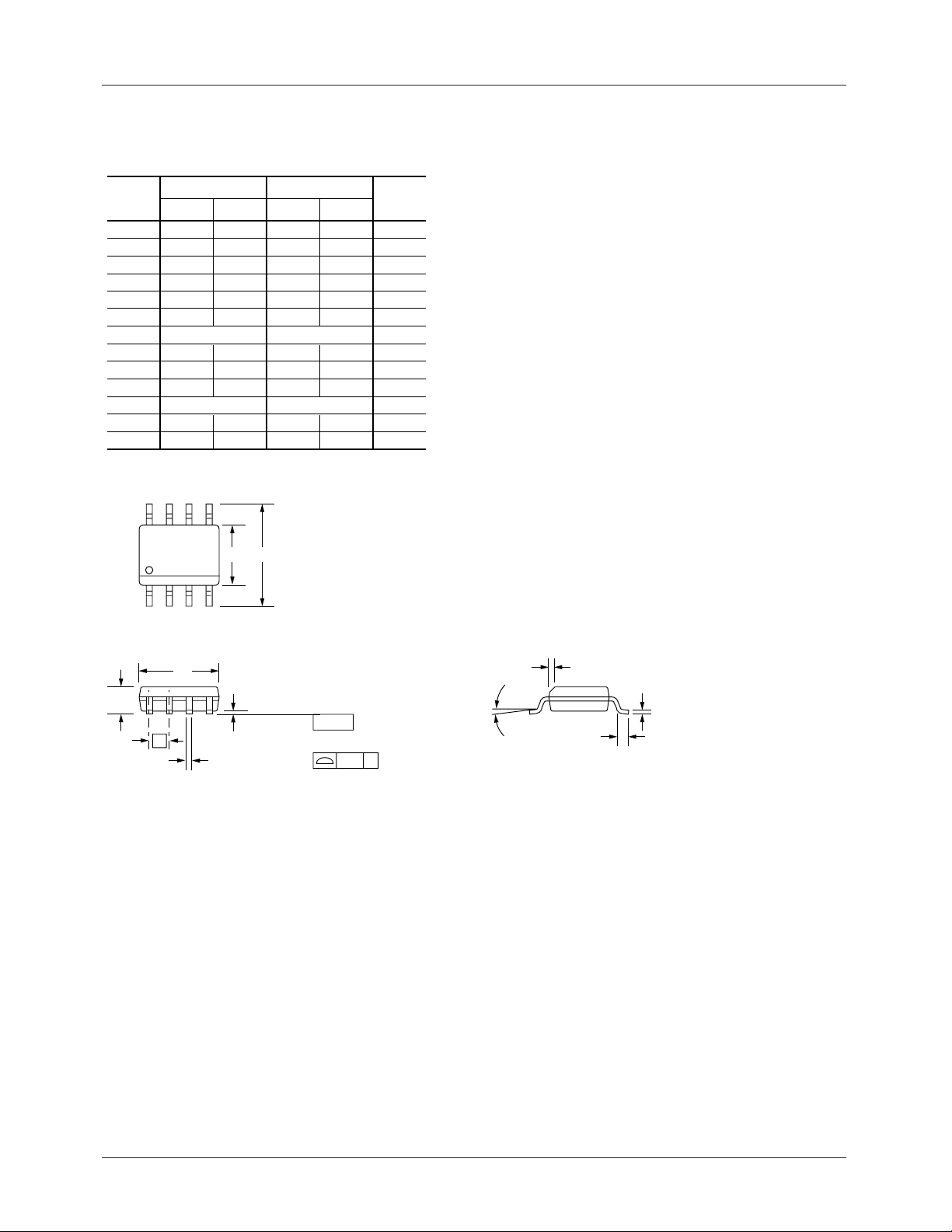
Mechanical Dimensions
8-Lead Plastic Surface Mount (SOIC)
Symbol
A .053 .069 1.35 1.75
A1 .004 .010 0.10 0.25
B .013 0.33
C .0075 .010 0.20 0.25
D .189 .197 4.80 5.00
E .150 .158 3.81 4.01
e
H
h
L .016 .050 0.40 1.27
N8 8
α
ccc .004 0.10——
85
14
Inches
Min. Max. Min. Max.
.020 0.51
.050 BSC 1.27 BSC
.228 .244 5.79 6.20
.010 .020 0.25 0.50
0° 8° 0° 8°
EH
Millimeters
Notes
Notes:
1.
Dimensioning and tolerancing per ANSI Y14.5M-1982.
2.
"D" and "E" do not include mold flash. Mold flash or
protrusions shall not exceed .010 inch (0.25mm).
3.
"L" is the length of terminal for soldering to a substrate.
4.
5
2
2
3
6
Terminal numbers are shown for reference only.
5.
"C" dimension does not include solder finish thickness.
6.
Symbol "N" is the maximum number of terminals.
D
A
e
B
A1
SEATING
PLANE
– C –
LEAD COPLANARITY
ccc C
α
h x 45°
C
L
14 REV. 1.0.9 1/28/03
Page 15
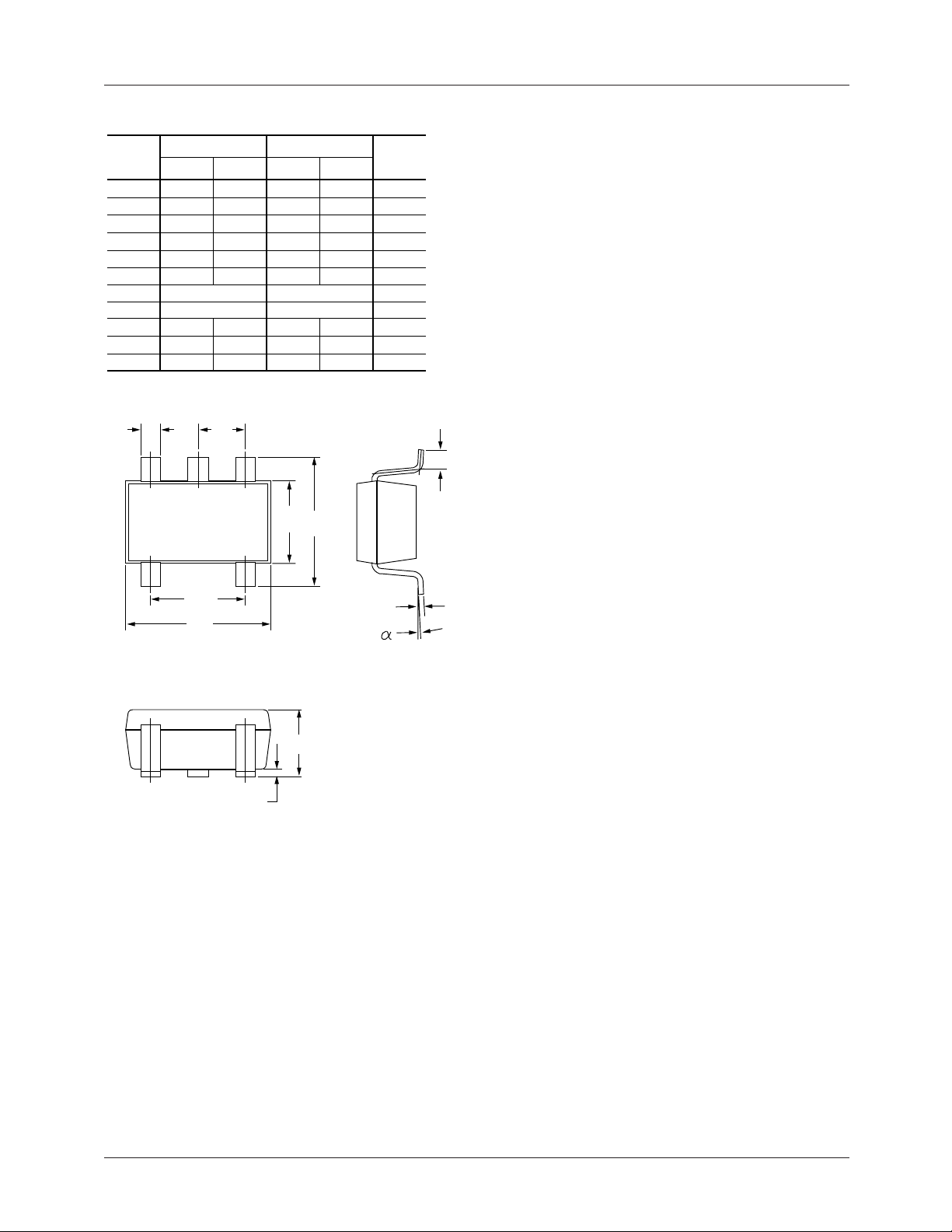
5-Lead Plastic Surface Mount (SOT-23-5)
ILC7083/ILC7084
Symbol
A .035 .057
A1 .000 .006
B .008
c .003 .010
D .106 .122
E .059 .071
e
e1
H .087 .126
L
α
B
Inches
Min. Max. Min. Max.
.020
.037 BSC
.075 BSC
.004 .024 .10 .60
0° 10°
e
Millimeters
.90 1.45
.00 .15
.20
.08 .25
2.70 3.10
1.50 1.80
2.20 3.20
0° 10°
E
.50
.95 BSC
1.90 BSC
H
Notes
Notes:
1.
Package outline exclusive of mold flash & metal burr.
2.
Package outline exclusive of solder plating.
3.
EIAJ Ref Number SC-74A.
L
e1
D
c
A
A1
REV. 1.0.9 1/28/03 15
Page 16
ILC7083/ILC7084
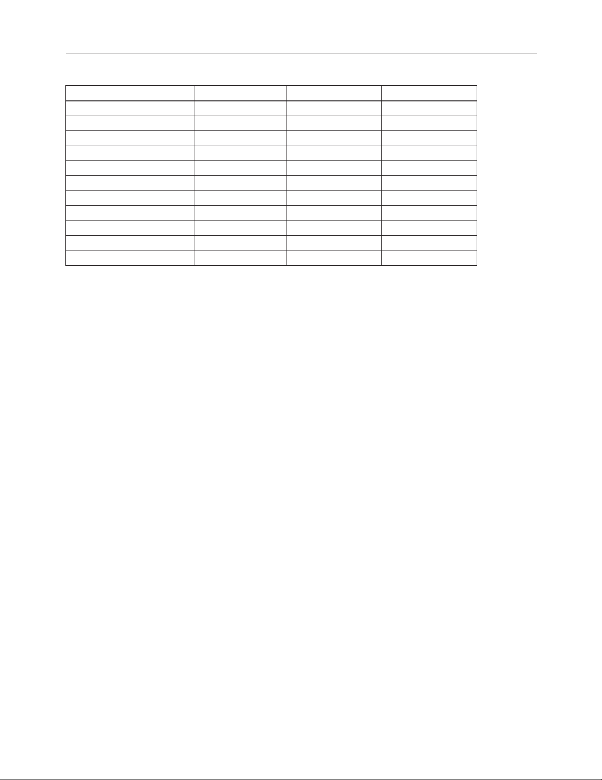
Ordering Information (T
= -40°C to +85°C)
A
Part Number Output Voltage (V) Package Package Marking
ILC7083AIM525X 2.5 SOT-23-5 BM
ILC7083AIM527X 2.7 SOT-23-5 BN
ILC7083AIM5285X 2.85 SOT-23-5 BJ
ILC7083AIM530X 3.0 SOT-23-5 BB
ILC7083AIM533X 3.3 SOT-23-5 BC
ILC7083AIM536X 3.6 SOT-23-5 BD
ILC7083AIM550X 5.0 SOT-23-5 BE
ILC7083AIM5ADJX Adjustable SOT-23-5 BF
ILC7083AIK30X 3.0 SOIC-8 7083A1K3
ILC7083AIKADJ Adjustable SOIC-8 7083A1K
ILC7084AIM5ADJX Adjustable SOT-23-5 DF
DISCLAIMER
FAIRCHILD SEMICONDUCTOR RESERVES THE RIGHT TO MAKE CHANGES WITHOUT FURTHER NOTICE TO
ANY PRODUCTS HEREIN TO IMPROVE RELIABILITY, FUNCTION OR DESIGN. FAIRCHILD DOES NOT ASSUME
ANY LIABILITY ARISING OUT OF THE APPLICATION OR USE OF ANY PRODUCT OR CIRCUIT DESCRIBED HEREIN;
NEITHER DOES IT CONVEY ANY LICENSE UNDER ITS PATENT RIGHTS, NOR THE RIGHTS OF OTHERS.
LIFE SUPPORT POLICY
FAIRCHILD’S PRODUCTS ARE NOT AUTHORIZED FOR USE AS CRITICAL COMPONENTS IN LIFE SUPPORT DEVICES
OR SYSTEMS WITHOUT THE EXPRESS WRITTEN APPROVAL OF THE PRESIDENT OF FAIRCHILD SEMICONDUCTOR
CORPORATION. As used herein:
1. Life support devices or systems are devices or systems
which, (a) are intended for surgical implant into the body,
or (b) support or sustain life, and (c) whose failure to
perform when properly used in accordance with
instructions for use provided in the labeling, can be
reasonably expected to result in a significant injury of the
user.
www.fairchildsemi.com
2. A critical component in any component of a life support
device or system whose failure to perform can be
reasonably expected to cause the failure of the life support
device or system, or to affect its safety or effectiveness.
1/28/03 0.0m 001
2003 Fairchild Semiconductor Corporation
Stock#DS30007083
 Loading...