

Page 1

For Power Management
Application
Data Sheet, Aug. 2010
Control Integrated POwer
System ( CIPOS™)
IGCM20F60GA
http://www.lspst.com
Page 2

CIPOS™ IGCM20F60GA
Revision History: 2010-08 Ver.1.1
Previous Version: Datasheet Ver. 1.0
Page
Subjects (major changes since last revision)
11
t
FLTCLR
Authors: Junho Song, Junbae Lee and Daewoong Chung
Edition 2010-07
Published by
LS Power Semitech Co., Ltd.
Seoul, Korea
© LS Power Semitech Co., Ltd.
All Rights Reserved.
Attention please!
The information given in this data sheet shall in no event be regarded as a guarantee of conditions or
characteristics. With respect to any examples or hints given herein, any typical values stated herein and/or
any information regarding the application of the device, LS Power Semitech Co., Ltd. hereby disclaims any
and all warranties and liabilities of any kind, including without limitation warranties of non-infringement of
intellectual property rights of any third party.
Information
For further information on technology, delivery terms and conditions and prices please contact your nearest
LS Power Semitech Co., Ltd. office or representatives (http://www.lspst.com).
Warnings
Due to technical requirements components may contain dangerous substances. For information on the types
in question please contact your nearest LS Power Semitech Co., Ltd. office or representatives.
LS Power Semitech Co., Ltd. components may only be used in life-support devices or systems with the
express written approval LS Power Semitech Co., Ltd., if a failure of such components can reasonably be
expected to cause the failure of that life-support device or system, or to affect the safety or effectiveness of
that device or system. Life support devices or systems are intended to be implanted in the human body, or to
support and/or maintain and sustain and/or protect human life. If they fail, it is reasonable to assume that the
health of the user or other persons may be endangered.
Data Sheet 2/14 Aug. 2010
Page 3

CIPOS™ IGCM20F60GA
Table of Contents
CIPOS™ Control Integrated POwer System.................................................................................................. 4
Features ........................................................................................................................................................ 4
Target Applications ..................................................................................................................................... 4
Description ................................................................................................................................................... 4
System Configuration ................................................................................................................................. 4
Pin Configuration .............................................................................................................................................. 5
Internal Electrical Schematic ........................................................................................................................... 5
Pin Assignment ................................................................................................................................................. 6
Pin Description ............................................................................................................................................ 6
HIN(U,V,W) and LIN(U,V,W) (Low side and high side control pins, Pin 7 - 12) ..........................................6
VFO (Fault-output and NTC, Pin 14) ...........................................................................................................7
ITRIP (Over current detection function, Pin 15) ..........................................................................................7
VDD, VSS (Low side control supply and reference, Pin 13, 16) ..................................................................7
VB(U,V,W) and VS(U,V,W) (High side supplies, Pin 1, 2, 3, 4, 5, 6) ..........................................................7
NU, NV, NW (Low side emitter, Pin 17, 18, 19) ..........................................................................................7
P (Positive bus input voltage, Pin 23) ..........................................................................................................7
Absolute Maximum Ratings ............................................................................................................................. 8
Module Section ............................................................................................................................................ 8
RC-IGBT Section .......................................................................................................................................... 8
Control Section ............................................................................................................................................ 8
Recommended Operation Conditions ............................................................................................................ 9
Static Parameters............................................................................................................................................ 10
Dynamic Parameters ...................................................................................................................................... 11
Bootstrap Parameters .................................................................................................................................... 11
Thermistor ...................................................................................................................................................... 12
Mechanical Characteristics and Ratings ...................................................................................................... 12
Circuit of a Typical Application ..................................................................................................................... 13
Switching Times Definition ............................................................................................................................ 13
Package Outline .............................................................................................................................................. 14
Data Sheet 3/14 Aug. 2010
Page 4

CIPOS™ IGCM20F60GA
CIPOS™
Control Integrated POwer System
Dual In-Line Intelligent Power Module
3Φ-bridge 600V / 20A
Features
Fully isolated Dual In-Line molded module
Infineon reverse conducting IGBTs with
monolithic body diode
Rugged SOI gate driver technology with
stability against transient and negative voltage
Allowable negative VS potential up to -11V for
signal transmission at VBS=15V
Integrated bootstrap functionality
Over current shutdown
Temperature monitor
Under-voltage lockout at all channels
Low side emitter pins accessible for all phase
current monitoring (open emitter)
Cross-conduction prevention
All of 6 switches turn off during protection
Lead-free terminal plating; RoHS compliant
Target Applications
Dish washers
Refrigerators
Description
The CIPOS™ module family offers the chance for
integrating various power and control components
to increase reliability, optimize PCB size and
system costs.
It is designed to control three phase AC motors
and permanent magnet motors in variable speed
drives for applications like air conditioning,
refrigerator and washing machine. The package
concept is specially adapted to power applications,
which need good thermal conduction and
electrical isolation, but also EMI-save control and
overload protection. The features of Infineon
reverse conducting IGBT are combined with an
optimized SOI gate driver for excellent electrical
performance.
System Configuration
3 half bridges with reverse conducting IGBT
3Φ SOI gate driver
Thermistor
Pin-to-heasink creepage distance typ. 1.6mm
Washing machines
Air-conditioners
Fans
Low power motor drives
Data Sheet 4/14 Aug. 2010
Page 5
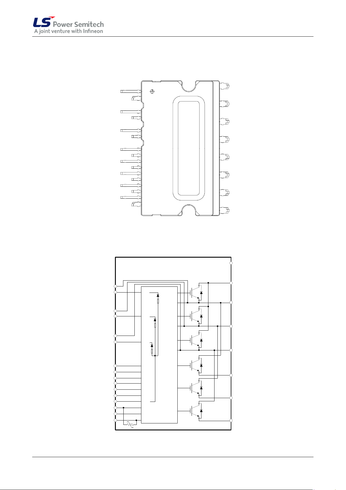
Pin Configuration
(1) VS(U)
(2) VB(U)
(3) VS(V)
(4) VB(V)
(5) VS(W)
(6) VB(W)
(7) HIN(U)
(8) HIN(V)
(9) HIN(W)
(10) LIN(U)
(11) LIN(V)
(12) LIN(W)
(13) VDD
(14) VFO
(15) ITRIP
(16) VSS
(23) P
(22) U
(21) V
(20) W
(19) NU
(18) NV
(17) NW
(24) NC
VSS
VDD
LIN3
LIN2
LIN1
VFO
ITRIP
LO3
LO2
LO1
HO1
HO2
HO3
VB1
VS1
VB2
VS2
VB3
VS3
HIN3
HIN2
HIN1
NW (17)
NV (18)
W (20)
V (21)
U (22)
P (23)
(2) VB(U)
(15) ITRIP
(14) VFO
(10) LIN(U)
(11) LIN(V)
(12) LIN(W)
(16) VSS
(13) VDD
(4) VB(V)
(6) VB(W)
(7) HIN(U)
(8) HIN(V)
(9) HIN(W)
(1) VS(U)
(3) VS(V)
(5) VS(W)
NU (19)
NC (24)
Thermistor
RBS1
RBS2
RBS3
CIPOS™ IGCM20F60GA
Bottom View
Figure 1: Pin configuration
Internal Electrical Schematic
Figure 2: Internal schematic
Data Sheet 5/14 Aug. 2010
Page 6
CIPOS™ IGCM20F60GA
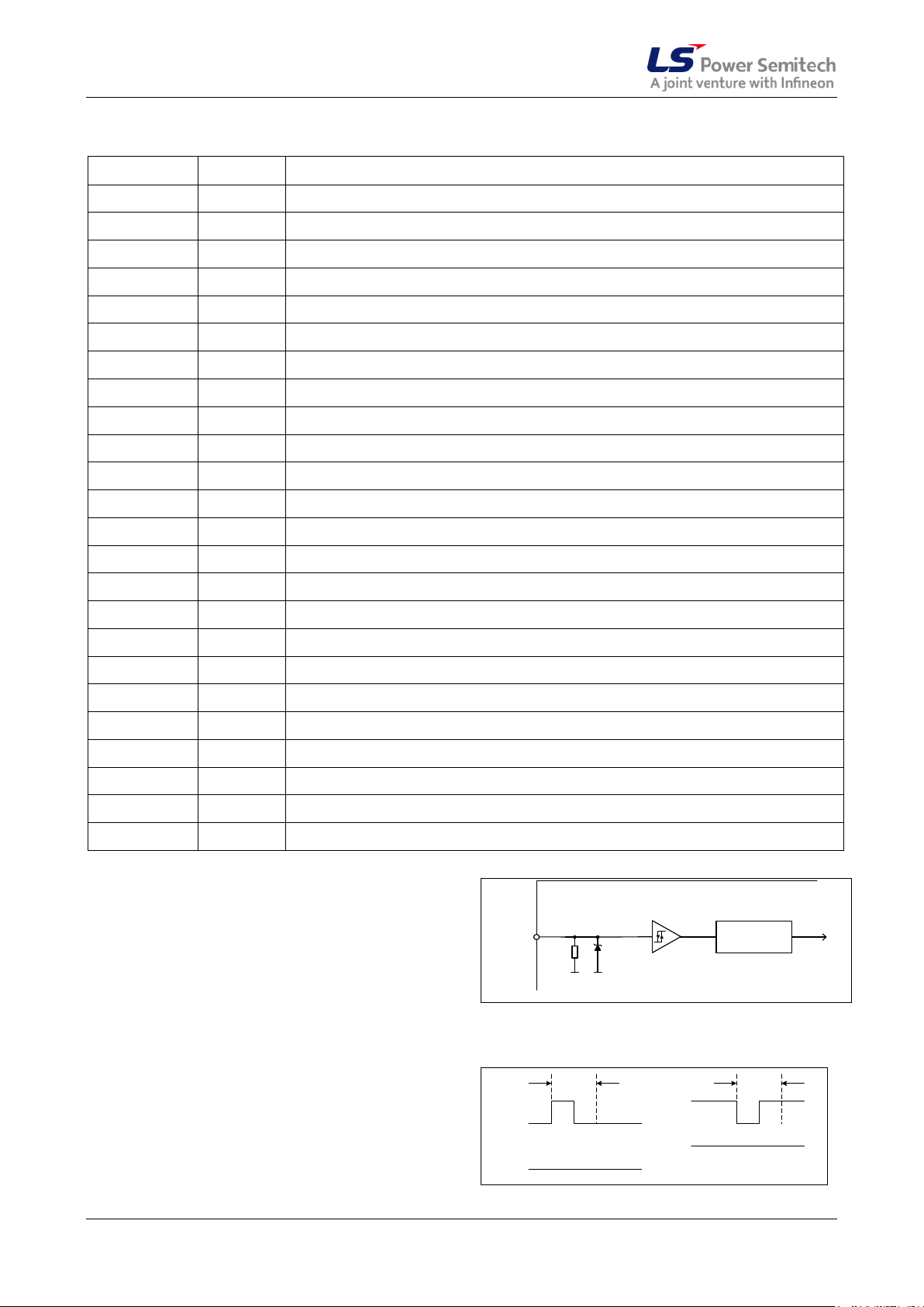
Pin Number
Pin Name
Pin Description
1
VS(U)
U-phase high side floating IC supply offset voltage
2
VB(U)
U-phase high side floating IC supply voltage
3
VS(V)
V-phase high side floating IC supply offset voltage
4
VB(V)
V-phase high side floating IC supply voltage
5
VS(W)
W-phase high side floating IC supply offset voltage
6
VB(W)
W-phase high side floating IC supply voltage
7
HIN(U)
U-phase high side gate driver input
8
HIN(V)
V-phase high side gate driver input
9
HIN(W)
W-phase high side gate driver input
10
LIN(U)
U-phase low side gate driver input
11
LIN(V)
V-phase low side gate driver input
12
LIN(W)
W-phase low side gate driver input
13
VDD
Low side control supply
14
VFO
Fault output / Temperature monitor
15
ITRIP
Over current shutdown input
16
VSS
Low side control negative supply
17
NW
W-phase low side emitter
18
NV
V-phase low side emitter
19
NU
U-phase low side emitter
20
W
Motor W-phase output
21
V
Motor V-phase output
22
U
Motor U-phase output
23
P
Positive bus input voltage
24
NC
No Connection
UZ=10.5V
INPUT NOISE
FILTER
k5
Schmitt-Trigger
SWITCH LEVEL
VIH; V
IL
LINx
HINx
Figure 3: Input pin structure
HIN
LIN
HO
LO
low
high
t
FILIN
t
FILIN
a) b)
HIN
LIN
HO
LO
Figure 4: Input filter timing diagram
Pin Assignment
Pin Description
HIN(U,V,W) and LIN(U,V,W) (Low side and high
side control pins, Pin 7 - 12)
These pins are positive logic and they are
responsible for the control of the integrated IGBT.
The Schmitt-trigger input threshold of them are
such to guarantee LSTTL and CMOS compatibility
down to 3.3V controller outputs. Pull-down resistor
of about 5k is internally provided to pre-bias
inputs during supply start-up and a zener clamp is
provided for pin protection purposes. Input
schmitt-trigger and noise filter provide beneficial
noise rejection to short input pulses.
The noise filter suppresses control pulses which
are below the filter time t
according to Figure 4.
Data Sheet 6/14 Aug. 2010
. The filter acts
FILIN
Page 7
CIPOS™ IGCM20F60GA
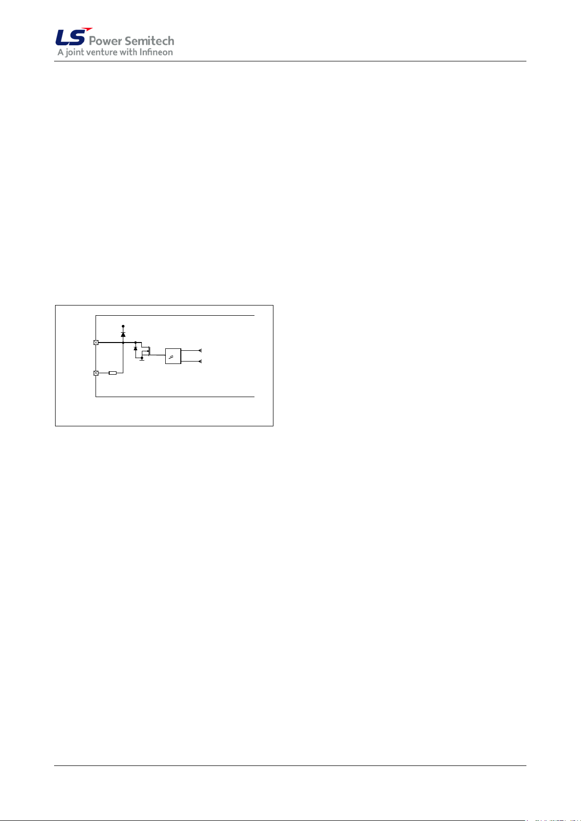
Figure 5: Internal circuit at pin VFO
VFO
CIPOS™
VSS
> 1 from uv
-
detection
VDD
R
ON
,
FLT
from ITRIP
-
Latch
Thermistor
It is recommended for proper work of CIPOS™
not to provide input pulse-width lower than 1us.
The integrated gate drive provides additionally a
shoot through prevention capability which avoids
the simultaneous on-state of two gate drivers of
the same leg (i.e. HO1 and LO1, HO2 and LO2,
HO3 and LO3). When two inputs of a same leg
are activated, only former activated one is
activated so that the leg is kept steadily in a safe
state.
A minimum deadtime insertion of typ 380ns is also
provided by driver IC, in order to reduce crossconduction of the external power switches.
VFO (Fault-output and NTC, Pin 14)
The VFO pin indicates a module failure in case of
under voltage at pin VDD or in case of triggered
over current detection at ITRIP. A pull-up resistor
is externally required to bias the NTC.
The IC shuts down all the gate drivers power
outputs, when the VDD supply voltage is below
V
= 10.4V. This prevents the external power
DDUV-
switches from critically low gate voltage levels
during on-state and therefore from excessive
power dissipation.
VB(U,V,W) and VS(U,V,W) (High side supplies,
Pin 1, 2, 3, 4, 5, 6)
VB to VS is the high side supply voltage. The high
side circuit can float with respect to VSS following
the external high side power device emitter
voltage.
Due to the low power consumption, the floating
driver stage is supplied by integrated bootstrap
circuit.
The under-voltage detection operates with a rising
supply threshold of typical V
falling threshold of V
DDUV-
= 10.4V.
= 12.1V and a
BSUV+
VS(U,V,W) provide a high robustness against
negative voltage in respect of VSS of -50V
transiently. This ensures very stable designs even
under rough conditions.
The same pin provides direct access to the NTC,
which is referenced to VSS. An external pull-up
resistor connected to +5V ensures, that the
resulting voltage can be directly connected to the
microcontroller.
ITRIP (Over current detection function, Pin 15)
CIPOS™ provides an over current detection
function by connecting the ITRIP input with the
motor current feedback. The ITRIP comparator
threshold (typ 0.47V) is referenced to VSS ground.
A input noise filter (typ: t
= 530ns) prevents
ITRIPMIN
the driver to detect false over-current events.
Over current detection generates a shut down of
all outputs of the gate driver after the shutdown
propagation delay of typically 1000ns.
The fault-clear time is set to typical 65us.
NU, NV, NW (Low side emitter, Pin 17, 18, 19)
The low side emitters are available for current
measurements of each phase leg. It is
recommended to keep the connection to pin VSS
as short as possible in order to avoid unnecessary
inductive voltage drops.
P (Positive bus input voltage, Pin 23)
The high side IGBT are connected to the bus
voltage. It is recommended that the bus voltage
does not exceed 400 V.
VDD, VSS (Low side control supply and
reference, Pin 13, 16)
VDD is the low side supply and it provides power
both to input logic and to low side output power
stage. Input logic is referenced to VSS ground.
The under-voltage circuit enables the device to
operate at power on when a supply voltage of at
least a typical voltage of V
Data Sheet 7/14 Aug. 2010
= 12.1V is present.
DDUV+
Page 8
CIPOS™ IGCM20F60GA
Description
Condition
Symbol
Value
Unit
min
max
Storage temperature range
T
stg
-40
125
°C
Insulation test voltage
RMS, f=60Hz, t =1min
V
ISOL
2000
-
V
Operating case temperature range
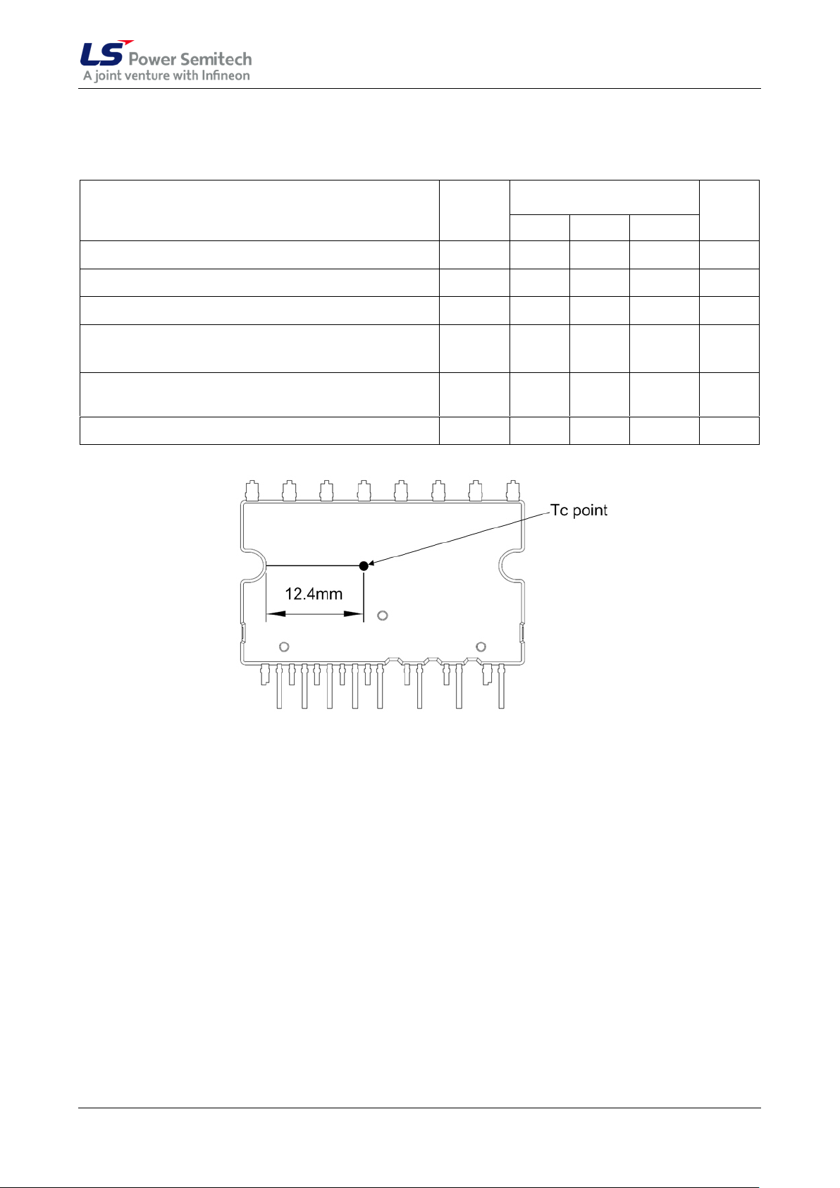
Refer to Figure 6
TC
-40
100
°C
Description
Condition
Symbol
Value
Unit
min
max
Max. blocking voltage
IC=250µA
V
CES
600 - V
Output current
TC = 25°C, TJ<150°C
TC = 80°C, TJ<150°C
IC
-20
-15
20
15
A
Maximum peak output current
less than 1ms
IC
-45
45
A
Short circuit withstand time
VDC ≤400V
tSC - 5
µs
Power dissipation per IGBT
P
tot
- 33
W
Operating junction temperature range
TJ
-40
150
°C
Single IGBT thermal resistance,
junction-case
R
thJC
-
3.84
K/W
Description
Condition
Symbol
Value
Unit
min
max
Module supply voltage
VDD
-1
20
V
High side floating supply voltage
(VB vs. VS)
VBS
-1
20
V
Input voltage
LIN, HIN, ITRIP
V
IN
V
ITRIP
-1
-1
10
10
V
Switching frequency
f
PWM
- 20
kHz
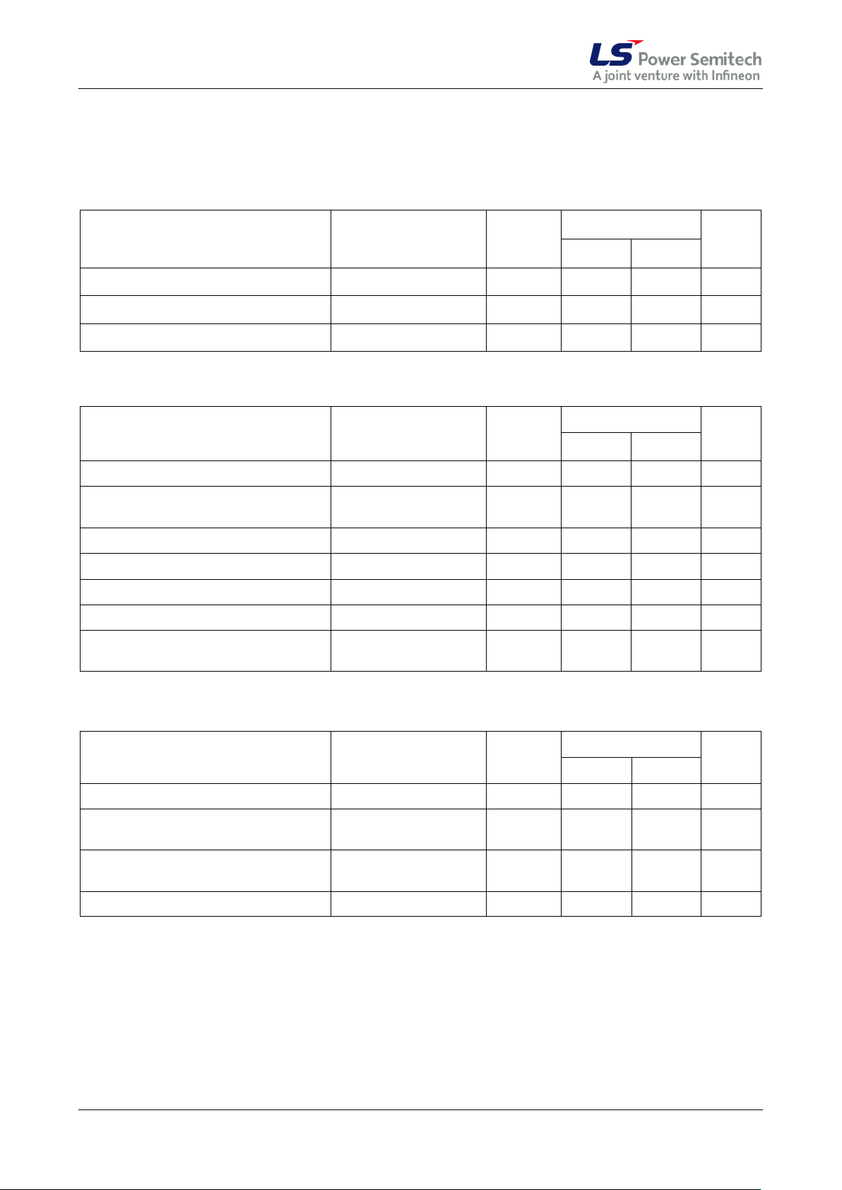
Absolute Maximum Ratings
(V
= 15V and TC = 25°C, if not stated otherwise)
DD
Module Section
RC-IGBT Section
Control Section
Data Sheet 8/14 Aug. 2010
Page 9
CIPOS™ IGCM20F60GA
Description
Symbol
Value
Unit
min
typ
max
DC link supply voltage
VDC 0 -
400
V
High side floating supply voltage (VB vs. VS)
VBS
13.5 - 18.5
V
Low side supply voltage
VDD
14.0
16
18.5
V
Control supply variation
Δ V
BS,
Δ VDD
-1
-1
-
1
1
V/µs
Logic input voltages LIN,HIN,ITRIP
V
IN
V
ITRIP
0
0
-
5
5
V
Between VSS - N (including surge)
VSS
-5 - 5
V
Recommended Operation Conditions
All voltages are absolute voltages referenced to VSS -potential unless otherwise specified.
Figure 6: TC measurement point
Data Sheet 9/14 Aug. 2010
Page 10
CIPOS™ IGCM20F60GA
Description
Condition
Symbol
Value
Unit
min
typ
max
Collector-Emitter saturation voltage
I
out
= 15A
TJ = 25°C
150°C
V
CE(sat)
- - 1.6
1.8
2.0
-
V
Emitter-Collector forward voltage
I
out
= -15A
TJ = 25°C
150°C
VF
- - 1.75
1.8
2.2
V
Collector-Emitter leakage current
V
CE
= 600V
I
CES
- - 1 mA
Logic "1" input voltage (LIN,HIN)
VIH
-
2.1
2.5
V
Logic "0" input voltage (LIN,HIN)
VIL
0.7
0.9 - V
ITRIP positive going threshold
V
IT,TH+
400
470
540
mV
ITRIP input hysteresis
V
IT,HYS
40
70 - mV
VDD and VBS supply under voltage
positive going threshold
V
DDUV+
V
BSUV+
10.8
12.1
13.0
V
VDD and VBS supply under voltage
negative going threshold
V
DDUV-
V
BSUV-
9.5
10.4
11.2
V
VDD and VBS supply under voltage
lockout hysteresis
V
DDUVH
V
BSUVH
1.0
1.7 - V
Input clamp voltage (HIN, LIN,
ITRIP)
Iin=4mA
V
INCLAMP
9.0
10.1
12.5
V
Quiescent VB
x
supply current (VB
x
only)
H
IN
= 0V
I
QBS
-
300
500
µA
Quiescent VDD supply current
(VDD only)
L
IN
= 0V, H
INX
=5V
I
QDD
-
370
900
µA
Input bias current
V
IN
= 5V
I
IN+
- 1
1.5
mA
Input bias current
V
IN
= 0V
I
IN-
- 2 -
µA
ITRIP input bias current
V
ITRIP
= 5V
I
ITRIP+
-
65
150
µA
VFO input bias current
VFO = 5V, V
ITRIP
= 0V
IFO
-
60 - µA
VFO output voltage
IFO = 10mA, V
ITRIP
= 1V
VFO
-
0.5 - V
Static Parameters
(V
= 15V and TC = 25°C, if not stated otherwise)
DD
Data Sheet 10/14 Aug. 2010
Page 11
CIPOS™ IGCM20F60GA
Description
Condition
Symbol
Value
Unit
min
typ
max
Turn-on propagation delay
V
LIN,HIN
= 5V; I
out
= 15A,
V
DC
= 300V
t
d(on)
-
650 - ns
Turn-on rise time
V
LIN,HIN
= 5V; I
out
= 15A,
V
DC
= 300V
tr - 45 - ns
Turn-off propagation delay
V
LIN,HIN
= 0V; I
out
= 15A,
V
DC
= 300V
t
d(off)
-
970 - ns
Turn-off fall time
V
LIN,HIN
= 0V; I
out
= 15A,
V
DC
= 300V
tf - 130 - ns
Short circuit propagation delay
From V
IT,TH+
to 10% ISC
t
SCP
-
1250
-
ns
Input filter time ITRIP
V
ITRIP
= 1V
t
ITRIPmin
-
530 - ns
Input filter time at LIN, HIN for turn
on and off
V
LIN,HIN
= 0V & 5V
t
FILIN
-
290 - ns
Fault clear time after ITRIP-fault
V
ITRIP
= 1 V
t
FLTCLR
40
65
130
µs
Deadtime between low side and
high side
DT
PWM
1.5 - -
µs
Deadtime of gate drive circuit
DTIC
380 ns
IGBT turn-on energy (includes
reverse recovery of diode)
V
DC
= 300V, IC = 15A,
TJ = 25°C
150°C
Eon
-
-
400
605
-
-
µJ
IGBT turn-off energy
V
DC
= 300V, IC = 15A,
TJ = 25°C
150°C
E
off
-
-
430
625
-
-
µJ
Diode recovery energy
V
DC
= 300V, IC = 15A,
TJ = 25°C
150°C
E
rec
-
-
95
225
-
-
µJ
Description
Condition
Symbol
Value
Unit
min
typ
max
Repetitive peak
reverse voltage
V
RRM
600
V
Bootstrap resistance of
U-phase1
VS2 or VS3=300V, TJ=25°C
VS2 and VS3=0V, TJ=25°C
VS2 or VS3=300V, TJ=125°C
VS2 and VS3=0V, TJ=125°C
R
BS1
35
40
50
65
Reverse recovery time
IF=0.6A, di/dt=80A/µs
t
rr_BS
50 ns
Forward voltage drop
IF=20mA, VS2 and VS3=0V
V
F_BS
2.6 V
1
Dynamic Parameters
(V
= 15V and TC = 25°C, if not stated otherwise)
DD
Bootstrap Parameters
(TC = 25°C, if not stated otherwise)
R
and R
BS2
Data Sheet 11/14 Aug. 2010
have same values to R
BS3
.
BS1
Page 12
CIPOS™ IGCM20F60GA
Description
Condition
Symbol
Value
Unit
min
typ
max
Resistor
T
NTC
= 25°C
R
NTC
-
85
-
k
B-constant of NTC
(Negative temperature coefficient)
B(25/100)
-
4092
-
K
Description
Condition
Value
Unit
min
typ
max
Mounting torque
M3 screw and washer
0.59
0.69
0.78
Nm
Flatness
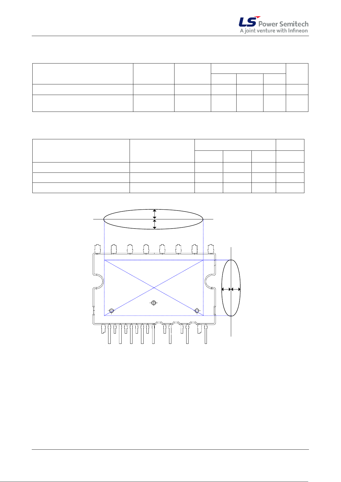
Refer to Figure 7
-50
-
100
µm
Weight
- 6.15 - g
+
+
-
-
Figure 7: Flatness measurement position
Thermistor
Mechanical Characteristics and Ratings
Data Sheet 12/14 Aug. 2010
Page 13
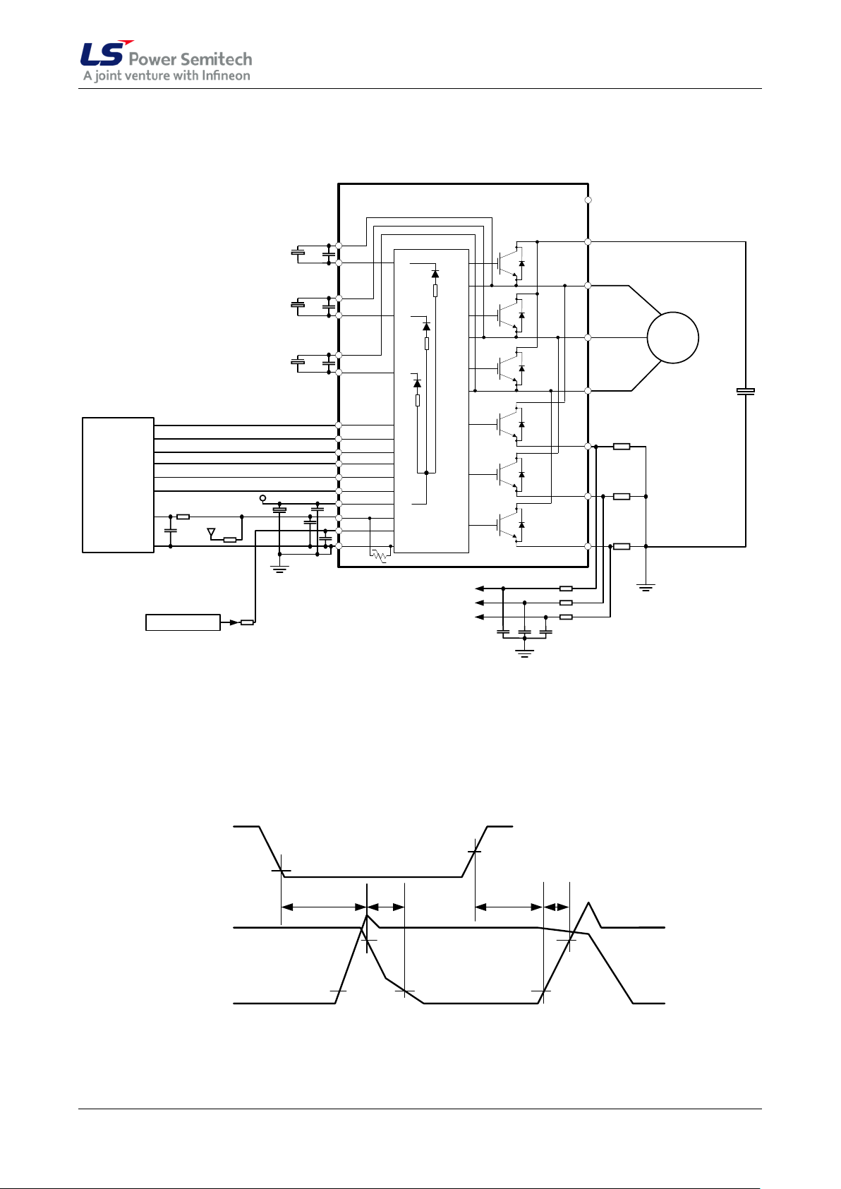
CIPOS™ IGCM20F60GA
3-ph AC
Motor
Micro
Controller
VDD line
5 or 3.3V line
Signal
for short-circuit protection
U-phase current sensing
V-phase current sensing
W-phase current sensing
U
VSS
VDD
LIN3
LIN2
LIN1
VFO
ITRIP
LO3
LO2
LO1
HO1
HO2
HO3
VB1
VS1
VB2
VS2
VB3
VS3
HIN3
HIN2
HIN1
NW (17)
NV (18)
W (20)
V (21)
U (22)
P (23)
(2) VB(U)
(15) ITRIP
(14) VFO
(10) LIN(U)
(11) LIN(V)
(12) LIN(W)
(16) VSS
(13) VDD
(4) VB(V)
(6) VB(W)
(7) HIN(U)
(8) HIN(V)
(9) HIN(W)
(1) VS(U)
(3) VS(V)
(5) VS(W)
NU (19)
NC (24)
Thermistor
RBS1
RBS2
RBS3
HIN
LIN
iCU, iCV, i
CW
v
CEU
, v
CEV
, v
CEW
0.9V
2.1V
90%
10%
10% 10%
90%
t
d(off)
t
f
t
d(on)
t
r
Figure 9: Switching times definition
Circuit of a Typical Application
Figure 8: Application circuit
Switching Times Definition
Data Sheet 13/14 Aug. 2010
Page 14
CIPOS™ IGCM20F60GA
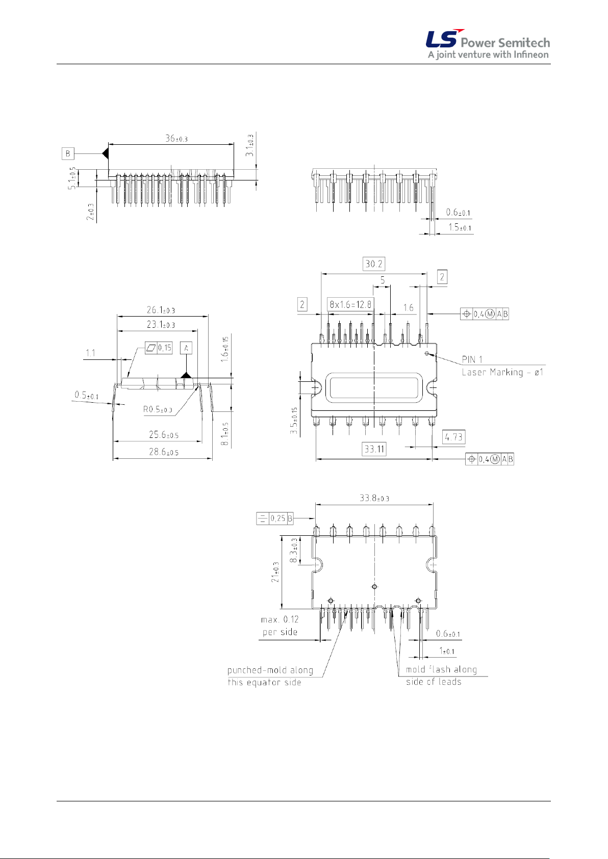
Package Outline
Data Sheet 14/14 Aug. 2010
 Loading...