

Page 1
®
Integrated Device Technology, Inc.
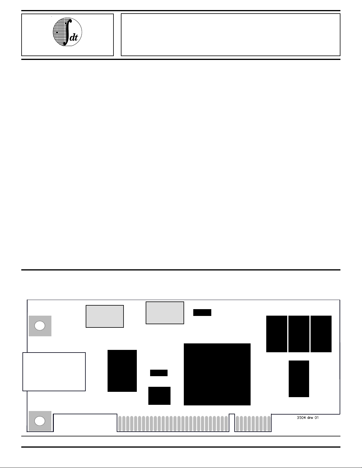
NICStAR™ Reference Design
155Mbps Network Interface
Card (NIC)
ADVANCE INFORMATION
IDT77904C/D
IDT77905C/D
FEATURES:
• Complete 155Mbps PCI-bus ATM Network Interface
Card
• Supports 33MHz, 32-bit PCI bus
• 155Mbps Multimode fiber optical interface (77904)
• 155Mbps UTP-5 PHY interface (77905)
• Complete reference design including schematics, bill of
materials, and data bases needed for production.
• Capable of supporting up to 16K receive connections
• Supports tens of thousands of transmit connections
•E2 PROM layout for Sub-vendor ID
• Small Form Factor: 2.5 x 6 inches
• "SARWIN" software evaluation program available for
Windows 3.1™
• Third Party Software available:
- Telogy Networks
Windows NT™ Drivers and other Windows Drivers
21 Firstfield Road, Gaithersburg, Maryland 20878
(301) 527-2788 (phone) (301) 417-0324 (FAX)
hluterman@telogy.com
- Harris & Jefferies
Novel Netware™ Drivers
888 Washington Street, Dedham,
Massachusetts, 02026
(617) 329-3200 (phone) (617) 329-4148 (FAX)
chrisb@hjinc,com
- Advancenet Systems Inc.
Windows NT™ and Windows 95™ Drivers
406 Timbermill Rd., Durham, North Carolina 27713
(919) 544-5601 (phone) (919) 544-4601 (FAX)
j.harford@ieee.org or
75141,2635@compuserve.com
DESCRIPTION:
The IDT77904 and IDT77905 are designed to provide
stable reference platforms for evaluation, design, and production of a 155Mbps NIC. The IDT77904 provides a fiber media
physical (PHY) interface; the 77905 supports Unshielded
Twisted Pair, Category 5 (UTP-5) cabling. Otherwise identical, they both feature complete PCI-bus ATM NIC functionality, plugging directly into PCI bus expansion slots.
COMPATIBILITY AND CONFIGURATION
The board is designed for use in PCI systems, which may
include PC compatibles, MIPS, Alpha, Windows NT systems,
future PowerPC Macintosh systems, and so on. It supports
the 32 bit, 33 MHz, 5V part of the PCI spec, although this also
permits operation in a 64-bit, 33 MHz, 5V PCI slot.
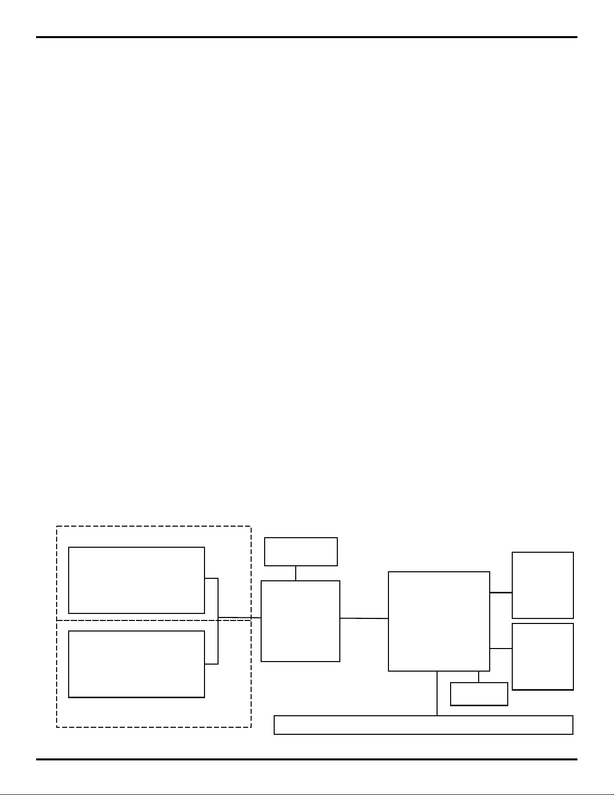
OVERVIEW
The heart of the board is the IDT 77201 NICStAR™, which
is an ATM Segmentation And Reassembly (SAR) controller.
The NICStAR™ connects directly to the PCI bus, a private
FUNCTIONAL BLOCK DIAGRAM
19MHz
Osc
Osc
77904/5C only
ODL (77904C/D)
50MHz
or
RJ45 +
Magnetics
IDT
77155
PHY
IDT74FCT
3384Q
(77905C/D)
PAL
COMMERCIAL TEMPERATURE RANGE JANUARY 1997
©1996 Integrated Device Technology, Inc.
8.14 1
2
PROM
E
32K
x8
SRAM
IDT
77201
SAR
32K
x8
SRAM
32K
x8
SRAM
32K
x8
SRAM
Page 2
IDT77904C/D/77905C/D ADVANCED INFORMATION
NICStAR™ Reference Design Commercial Temperature Range
SRAM/EPROM bus, and the Utopia PHY interface. The PHY
device is aIDT 77155 PHY. The PHY device connects in turn
to a Hewlett-Packard HFBR-5103 Optical Data Link (ODL)
device for the fiber optic connection (IDT77904), or to a Micro
Linear ML6672CH transciever for the UTP-5 connection
(IDT77905). The ODL incorporates its own fiber optic connectors; the UTP option requires a line interface/filter transformer
and a standard RJ-45 jack.
THEORY OF OPERATION
The NICStAR™ has 50 signal pins which connect directly
to the PCI bus edge connector. 32 of these are multiplexed
address/data signals, and the remainder are control signals.
The NICStAR™ is compatible with the 5V, 33 MHz portion of
the PCI spec, so the eval board will work in motherboards with
32 or 64 bit, 5V, 33 MHz slots. The board will not work in 3.3V
slots.
The NICStAR™ receives two clock input signals. One is
from the PCI bus, and this one can vary from DC to 33.333MHz.
The other is from a local oscillator on the 77904/5. The
NICStAR™’s main clock is the SAR_CLK. It runs typically at
50 MHz. The rate of the Utopia interface, PHY_CLK is
connected to a devide by 2 output clock from the SAR.
Optionally, this clock can be supplied via a separate osallator,
the PHY clock, and runs typically at 25 MHz. All clock
oscillators on the board have ferrite-bead power supply filters,
and both SAR oscillator sockets have 33 Ohm source series
and 330/220 Ohm end parallel termination resistors provided
for optimum signal integrity.
The NICStAR™ has a private local SRAM/EPROM data
bus, SR_I/O[31:0] and address bus, SR_A[16:0]. It also
supports a four-wire private EEPROM bus, three of which are
outputs (EE_SCLK, EE_CS#, EE_DO) and one of which is an
input (EE_DI).
NICStAR™ supports 4 32Kx8 or 128Kx8 asynchronous
SRAMS. SRAM timing is fixed at one cycle. The NICStAR™
spec requires 20 ns access time SRAMs when the NICStAR™
is running at 50 MHz.
NICStAR™ supports 1 32Kx8 or 128Kx8 EPROM. EPROM
timing is fixed at three cycles. NICStAR™ requires a 70 ns
access time EPROM.
NICStAR™ supports 1 EEPROM device. The four EEPROM
signals are completely under software control, so access
times and protocols can be specified by the user. The eval
board uses a Xicor X25020 EEPROM. This device requires
EE_CS# to be asserted low during all operations. Control or
data bits are taken from EE_DO at the rising edge of EE_SCLK,
and EE_DI changes on the falling edge of EE_SCLK. Refer to
the X25020 documentation for more information. The 77904/
5 provides LEDs on EE_DO (D6) and EE_SCLK (D5). These
LEDs illuminate when the corresponding signal is asserted
low, and may be used to signal status to the user when the
EEPROM is not being accessed.
The NICStAR™ has a multiplexed utility bus, UTL_AD[7:0]
plus five UTL control signals. This bus may be used to
communicate with external 8-bit devices. The 77904/5 uses
the utility bus in this way to communicate with the registers on
the PHY. This interface is also under software control, so
protocol can be specified by the user.
FUNCTIONAL BLOCK DIAGRAM
77904 only
Optial Data
Link (ODL)
Fiber Interface)
ATM Network
RJ-45
Connector
and
Magnetics
77905 only
19MHz
OSC
IDT 77155
SwitchSTAR
PHY
8.14 2
SRAM
IDT 77201
NICStAR
SAR
50MHz
OSC
E2 PROM
5V 33-MHz 32-bit PCI Bus
3504 drw 02
Page 3

IDT77904C/D/77905C/D ADVANCED INFORMATION
NICStAR™ Reference Design Commercial Temperature Range
SDH frames. RALM is connected to an LED to act as a “link
The last two buses on the NICStAR™ are the UTOPIA
detect” indicator.
transmit and receive buses. These follow the ATM Forum’s
specification of the UTOPIA interface. They run at the PHY_CLK
speed, with the NICStAR™ generating the TXCLK and RXCLK
signals to the PHY device.
77155 has a six-wire connection to the physical media
devices (PMD) which consists of three pairs of PECL-level
differential signals. One pair is transmit data, one pair is
receive data, and the last pair is signal detect, which can also
The PHY device used is the IDT 77155. It has the standard
transmit and receive UTOPIA interfaces, and a non-multiplexed utility bus for register access. The PHY utility data bus
and address bus are connected together on the eval board;
the NICStAR™ ALE signal defines the mode of this combined
bus in a way compatible with the NICStAR™ and the 77155
be connected as a single-ended PECL or CMOS signal. The
polarity of the connectors should be observed. The 77904/5
provides two PMD options (77904 and 77905), and includes
extensive termination circuitry with several possible configurations to provide the best possible signal integrity between
the PHY and the PMD.
SWITCHStAR™.
77904 Option
The 77155 reset input is driven by the NICStAR™’s
PHY_RST# input. IDT's 77155 also provides an INT# output
which is connected to the NICStAR™’s PHY_INT# input.
The 77904 interface is provided via a 9-pin fiber optical data
link (ODL) footprint which can be loaded with any standard 9pin ODL device. The 77904 is loaded with the HewlettPackard HFBR-5103, which is a short-haul device for multi-
The 77155 transmit and receive clock reference frequency
is provided by a 19.44 MHz oscillator. This device is specified
at 10 ppm accuracy to meet the ATM Forum requirements for
mode fiber, originally designed for FDDI. Other devices in the
HFBR-510x and -520x families should also work here, depending on the application.
155.52 Mbps operation. As with the other oscillators on the
eval board, this oscillator has a ferrite-bead power supply
filter, and a 33 Ohm source series termination resistor. End
termination is provided as part of a voltage divider network
designed to limit the input swing at the AC-coupled RRCLK
and TXCLK inputs on the 77155.
The 77155 has several control signals which are connected
to pullup and/or pulldown resistors on the eval board. Refer to
the 77155 documentation and the 77904/5 schematics for
more details. There are also several status outputs which are
not connected. One status output, RALM, goes high when any
of several different error conditions are detected by the PHY.
It is low only when a signal is present on the receive data
inputs, the 77155 is able to recover a valid clock from the
signal, and the data on the signal contains proper SONET OR
77905 Option
On the 77905 is a Micro Linear ML6672CH line interface
device intended for driving twisted-pair copper lines at high
data rates; it is characterized for 155 Mbps operation. Several
resistors and capacitors are provided on the 77905 to set
various line interface parameters on the ML6672CH. The line
interface side of the ML6672CH is connected to a Pulse
Engineering PE-68511 line interface transformer which is
designed for 155 Mbps operation over unshielded twisted pair
(UTP) cable. The connector used on the eval board is an
unshielded RJ-45 which must be low-profile to work in a
standard PC expansion slot. Unused pins on the RJ-45
connector go to a termination network to reduce crosstalk and
other forms of interference within the cable.
8.14 3
Page 4

IDT77904C/D/77905C/D ADVANCED INFORMATION
NICStAR™ Reference Design Commercial Temperature Range
ORDERING INFORMATION
IDT
NNNNN
Device Type
N
SAR
A
Power
NNN
Speed
A A
Package
Process/
Temp. Range
Blank
Blank
Blank
Blank
C
D
77904
77905
Commercial
With 77201 Rev. C3
With 77201 Rev. D
155Mb/s ATM Network Interface
Card (NIC) with Fiber Connection
155Mb/s ATM Network Interface
Card (NIC) with UTP5 Connection
3504 drw 03
3504 drw 03
ADVANCE INFORMATION DATASHEET: DEFINITION
"Advance Information" datasheets contain initial descriptions, subject to change, for products which are in development,
including features and block diagrams.
Datasheet Document History
8/22/96: Initial Draft
Integrated Device Technology, Inc. reserves the right to make changes to the specifications in this data sheet in order to improve design or performance and to supply the best possible product.
Integrated Device Technology, Inc.
2975 Stender Way, Santa Clara, CA 95054-3090 Telephone: (408) 727-6116 FAX 408-492-8674
8.14 4
 Loading...