

Page 1
CMOS SyncFIFO
™
64 x 9, 256 x 9, 512 x 9,
1,024 x 9, 2,048 x 9,
4,096 x 9 and 8,192 x 9
IDT72421, IDT72201
IDT72211, IDT72221
IDT72231, IDT72241
IDT72251
FEATURES:
••
• 64 x 9-bit organization (IDT72421)
••
••
• 256 x 9-bit organization (IDT72201)
••
••
• 512 x 9-bit organization (IDT72211)
••
••
• 1,024 x 9-bit organization (IDT72221)
••
••
• 2,048 x 9-bit organization (IDT72231)
••
••
• 4,096 x 9-bit organization (IDT72241)
••
••
8,192 x 9-bit organization (IDT72251)
•
••
••
• 10 ns read/write cycle time
••
••
• Read and Write Clocks can be independent
••
••
• Dual-Ported zero fall-through time architecture
••
••
•
Empty and Full Flags signal FIFO status
••
••
•
Programmable Almost-Empty and Almost-Full flags can be set
••
to any depth
••
Programmable Almost-Empty and Almost-Full flags default to
•
••
Empty+7, and Full-7, respectively
••
• Output enable puts output data bus in high-impedance state
••
••
• Advanced submicron CMOS technology
••
••
• Available in the 32-pin plastic leaded chip carrier (PLCC) and
••
32-pin Thin Quad Flat Pack (TQFP)
••
• For through-hole product please see the IDT72420/72200/72210/
••
72220/72230/72240 data sheet
••
• Industrial temperature range (–40
••
°°
°C to +85
°°
°°
°C) is available
°°
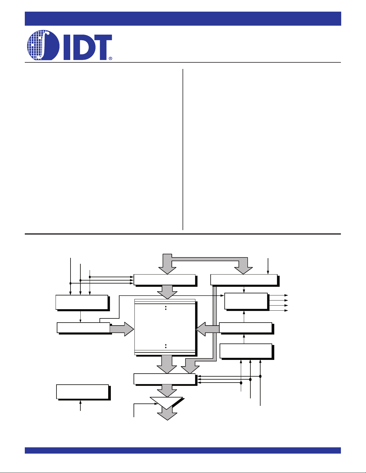
FUNCTIONAL BLOCK DIAGRAM
D
0
- D
WCLK
WEN1
WEN2
8
DESCRIPTION:
The IDT72421/72201/72211/72221/72231/72241/72251 SyncFIFO™
are very high-speed, low-power First-In, First-Out (FIFO) memories with
clocked read and write controls. These devices have a 64, 256, 512, 1,024,
2,048, 4,096, and 8,192 x 9-bit memory array, respectively. These FIFOs are
applicable for a wide variety of data buffering needs such as graphics, local area
networks and interprocessor communication.
These FIFOs have 9-bit input and output ports. The input port is controlled
by a free-running clock (WCLK), and two write enable pins (WEN1, WEN2).
Data is written into the Synchronous FIFO on every rising clock edge when the
write enable pins are asserted. The output port is controlled by another clock
pin (RCLK) and two read enable pins (REN1, REN2). The Read Clock can
be tied to the Write Clock for single clock operation or the two clocks can run
asynchronous of one another for dual-clock operation. An output enable pin
(OE) is provided on the read port for three-state control of the output.
The Synchronous FIFOs have two fixed flags, Empty (EF) and Full (FF).
Two programmable flags, Almost-Empty (PAE) and Almost-Full (PAF), are
provided for improved system control. The programmable flags default to
Empty+7 and Full-7 for PAE and PAF, respectively. The programmable flag
offset loading is controlled by a simple state machine and is initiated by asserting
the load pin (LD).
These FIFOs are fabricated using IDT’s high-speed submicron CMOS
technology.
LD
INPUT REGISTER
WRITE CONTROL
LOGIC
RAM ARRAY
64 x 9, 256 x 9,
WRITE POINTER
RESET LOGIC
RS
IDT and the IDT logo are registered trademarks of Integrated Device Technology, Inc. The SyncFIFO is a registered trademark of Integrated Device Technology, Inc.
512 x 9, 1,024 x 9,
2,048 x 9, 4,096 x 9,
8,192 x 9
OUTPUT REGISTER
OE
Q0 - Q
8
COMMERCIAL AND INDUSTRIAL TEMPERATURE RANGES
OFFSET REGISTER
FLAG
LOGIC
READ POINTER
READ CONTROL
LOGIC
RCLK
REN1
REN2
EF
PAE
PAF
FF
2655 drw01
SEPTEMBER 2002
1
2002 Integrated Device Technology, Inc. All rights reserved. Product specifications subject to change without notice. DSC-2655/2
Page 2
IDT72421/72201/72211/72221/72231/72241/72251 CMOS SyncFIFO™
64 x 9, 256 x 9, 512 x 9, 1,024 x 9, 2,048 x 9, 4,096 x 9 and 8,192 x 9
COMMERCIAL AND INDUSTRIAL
TEMPERATURE RANGES
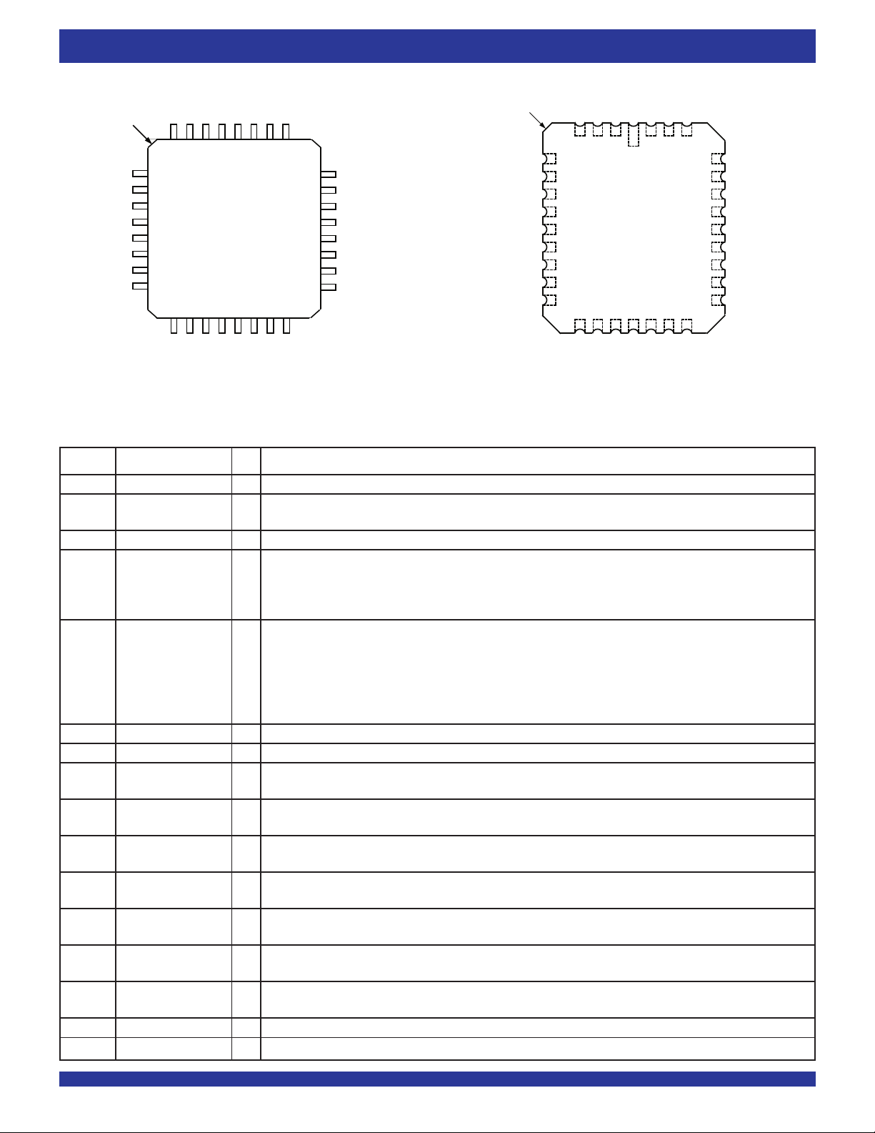
PIN CONFIGURATION
INDEX
D
D
PAF
PAE
GND
REN1
RCLK
REN2
7
8
D2D3D4D5D6D
OE
EF
FF
29 28
Q0Q
1
32 31 30
1
1
2
0
3
4
5
6
7
8
9 101112131415
D
27 26 25
2
Q3Q
Q
RS
24
WEN1
23
WCLK
22
WEN2/LD
21
CC
V
Q
8
20
Q
7
19
18
Q
6
17
Q
5
16
4
2655 drw 02
INDEX
D
D
PAF
PAE
GND
REN1
RCLK
REN2
OE
1
0
TQFP (PR32-1, order code: PF)
TOP VIEW
3
D
D
432132 31 30
5
6
7
8
9
10
11
12
13
14 15 16 17 18 19 20
FF
EF
PLCC (J32-1, order code: J)
TOP VIEW
6
4
D5D
D
0
Q1Q
Q
8
7
D
D
29
RS
28
WEN1
27
WCLK
26
WEN2/LD
25
CC
V
Q
8
24
Q
7
23
Q
6
22
21
Q
5
2
4
3
Q
2655 drw02a
Q
2
PIN DESCRIPTIONS
Symbol Name I/O Description
D0-D8 Data Inputs I Data inputs for a 9-bit bus.
RS Reset I When RS is set LOW, internal read and write pointers are set to the first location of the RAM array,FF and PAF
go HIGH, and PAE and EF go LOW. A reset is required before an initial WRITE after power-up.
WCLK Write Clock I Data is written into the FIFO on a LOW-to-HIGH transition of WCLK when the Write Enable(s) are asserted.
WEN1 Write Enable 1 I If the FIFO is configured to have programmable flags, WEN1 is the only write enable pin. When WEN1 is LOW,
data is written into the FIFO on every LOW-to-HIGH transition WCLK. If the FIFO is configured to have two write
enables, WEN1 must be LOW and WEN2 must be HIGH to write data into the FIFO. Data will not be written into
the FIFO if the FF is LOW.
WEN2/ Write Enable 2/ I The FIFO is configured at reset to have either two write enables or programmable flags. If WEN2/
LD
Load at reset, this pin operates as a second write enable. If WEN2/LD is LOW at reset, this pin operates as a control
to load and read the programmable flag offsets. If the FIFO is configured to have two write enables, WEN1 must
be LOW and WEN2 must be HIGH to write data into the FIFO. Data will not be written into the FIFO if the FF is
LOW. If the FIFO is configured to have programmable flags, WEN2/LD is held LOW to write or read the
programmable flag offsets.
Q0-Q8 Data Outputs O Data outputs for a 9-bit bus.
RCLK Read Clock I Data is read from the FIFO on a LOW-to-HIGH transition of RCLK when REN1 and REN2 are asserted.
REN1 Read Enable 1 I When REN1 and REN2 are LOW, data is read from the FIFO on every LOW-to-HIGH transition of RCLK.
Data will not be read from the FIFO if the EF is LOW.
REN2 Read Enable 2 I When REN1 and REN2 are LOW, data is read from the FIFO on every LOW-to-HIGH transition of RCLK.
Data will not be read from the FIFO if the EF is LOW.
OE Output Enable I When OE is LOW, the data output bus is active. If OE is HIGH, the output data bus will be in a high-impedance
state.
EF Empty Flag O When EF is LOW, the FIFO is empty and further data reads from the output are inhibited. When EF is HIGH, the
FIFO is not empty. EF is synchronized to RCLK.
PAE Programmable O When PAE is LOW, the FIFO is almost-empty based on the offset programmed into the FIFO. The default
Almost-Empty Flag offset at reset is Empty+7. PAE is synchronized to RCLK.
PAF Programmable O When PAF is LOW, the FIFO is almost-full based on the offset programmed into the FIFO. The default offset
Almost-Full Flag at reset is Full-7. PAF is synchronized to WCLK.
FF Full Flag O When FF is LOW, the FIFO is full and further data writes into the input are inhibited. When FF is HIGH, the FIFO
is not full. FF is synchronized to WCLK.
VCC Power One +5 volt power supply pin.
GND Ground One 0 volt ground pin.
LD is HIGH
2
Page 3
IDT72421/72201/72211/72221/72231/72241/72251 CMOS SyncFIFO™
64 x 9, 256 x 9, 512 x 9, 1,024 x 9, 2,048 x 9, 4,096 x 9 and 8,192 x 9
COMMERCIAL AND INDUSTRIAL
TEMPERATURE RANGES
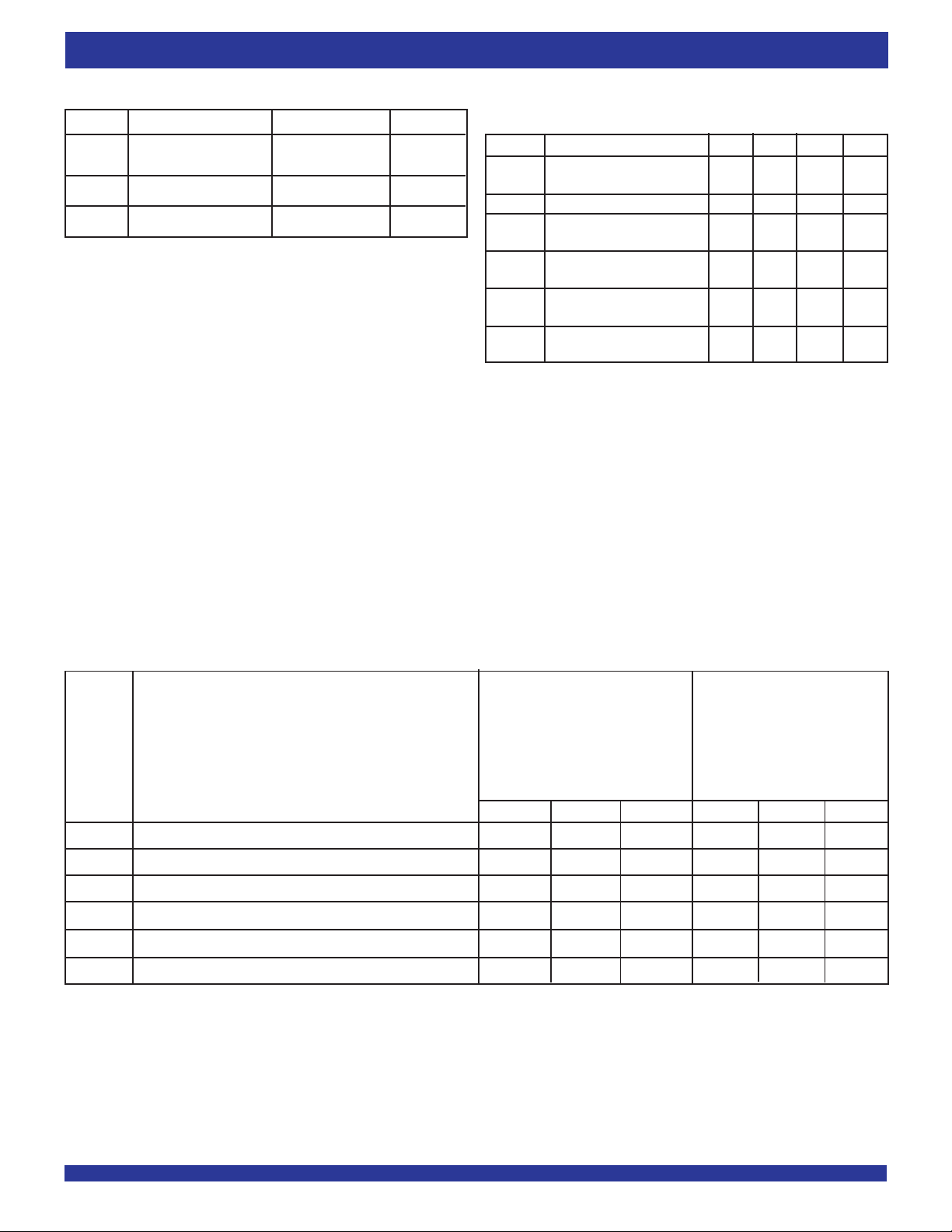
ABSOLUTE MAXIMUM RATINGS
Symbol Rating Com'l & Ind'l Unit
TERM Terminal Voltage with –0.5 to +7.0 V
V
Respect to GND
STG Storage Temperature –55 to +125 °C
T
I
OUT DC Output Current –50 to +50 mA
NOTE:
1. Stresses greater than those listed under ABSOLUTE MAXIMUM RATINGS may cause
permanent damage to the device. This is a stress rating only and functional operation
of the device at these or any other conditions above those indicated in the operational
sections of the specification is not implied. Exposure to absolute maximum rating
conditions for extended periods may affect reliability.
RECOMMENDED OPERATING
CONDITIONS
Symbol Parameter Min. Typ. Max. Unit
CC Supply Voltage 4.5 5.0 5.5 V
V
Commercial/Industrial
GND Supply Voltage 0 0 0 V
V
IH Input High Voltage 2.0 — — V
Commercial/Industrial
V
IL Input Low Voltage — — 0.8 V
Commercial/Industrial
T
A Operating Temperature 0 — +70 °C
Commercial
T
A Operating Temperature –40 — +85 °C
Industrial
DC ELECTRICAL CHARACTERISTICS
(Commercial: VCC = 5V ± 10%, TA = 0°C to +70°C; Industrial: VCC = 5V ± 10%, TA = –40°C to +85°C)
IDT72421
IDT72201
IDT72211
IDT72221
IDT72231
IDT72241 IDT72251
Com'l and Ind'l
tCLK = 10, 15, 25 ns tCLK = 10, 15, 25 ns
Symbol Parameter Min. Typ. Max. Min. Typ. Max.
(2)
I
LI
(3)
I
LO
V
OH
OL Output Logic “0” Voltage, IOL = 8mA — — 0.4 — — 0.4
V
(4,5,6)
I
CC1
(4,7)
I
CC2
NOTES:
1. Industrial temperature range product for the 15ns and 25ns speed grades are available as standard product.
2. Measurements with 0.4
3. OE ≥ V
4. Tested with outputs open (I
5. RCLK and WCLK toggle at 20 MHz and data inputs switch at 10 MHz.
6. Typical I
These equations are valid under the following conditions:
CC = 5V, TA = 25°C, fS = WCLK frequency = RCLK frequency (in MHz, using TTL levels), data switching at fS/2, CL = capacitive load (in pF).
V
7. All Inputs = V
Input Leakage Current (Any Input) –1 — 1 –1 — 1
Output Leakage Current –10 — 10 –10 — 10
Output Logic “1” Voltage, IOH = –2mA
2.4 — — 2.4 — —
Active Power Supply Current — — 35 — — 50
Standby Current — — 5 — — 5
≤≤
≤≤
IN
≤ VCC.
≤ V
≤≤
IH, 0.4 ≤ VOUT ≤ VCC.
CC1 = 1.7 + 0.7*fS + 0.02*CL*fS (in mA).
CC - 0.2V or GND + 0.2V, except RCLK and WCLK, which toggle at 20 MHz.
≤≤
OUT = 0).
(1)
Com'l and Ind'l
(1)
3
Page 4
IDT72421/72201/72211/72221/72231/72241/72251 CMOS SyncFIFO™
64 x 9, 256 x 9, 512 x 9, 1,024 x 9, 2,048 x 9, 4,096 x 9 and 8,192 x 9
COMMERCIAL AND INDUSTRIAL
TEMPERATURE RANGES
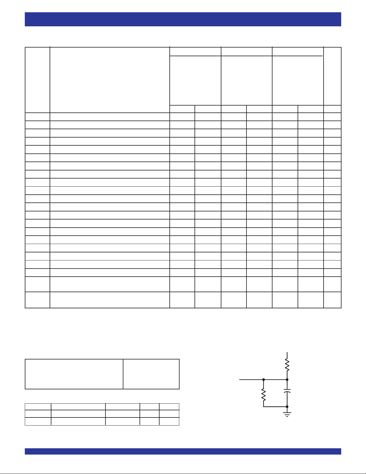
AC ELECTRICAL CHARACTERISTICS
(Commercial: VCC = 5V ± 10%, TA = 0°C to +70°C; Industrial: VCC = 5V ± 10%, TA = –40°C to +85°C)
Commercial Com'l & Ind'l
(1)
Com'l & Ind'l
IDT72421L10 IDT72421L15 IDT72421L25
IDT72201L10 IDT72201L15 IDT72201L25
IDT72211L10 IDT72211L15 IDT72211L25
IDT72221L10 IDT72221L15 IDT72221L25
IDT72231L10 IDT72231L15 IDT72231L25
IDT72241L10 IDT72241L15 IDT72241L25
IDT72251L10 IDT72251L15 IDT72251L25
Symbol Parameter Min. Max. Min. Max. Min. Max. Unit
fS Clock Cycle Frequency — 100 — 66.7 — 40 MH z
tA Data Access Time 2 6.5 2 10 2 15 ns
tCLK Clock Cycle Time 10 — 15 — 25 — ns
tCLKH Clock High Time 4.5 — 6 — 10 — ns
tCLKL Clock Low Time 4.5 — 6 — 10 — ns
tDS Data Setup Time 3 — 4 — 6 — ns
tDH Data Hold Time 0.5 — 1 — 1 — ns
tENS Enable Setup Time 3 — 4 — 6 — ns
tENH Enable Hold Time 0.5 — 1 — 1 — ns
tRS Reset Pulse Width
(2)
10 — 15 — 15 — ns
tRSS Reset Setup Time 8 — 10 — 15 — ns
tRSR Reset Recovery Time 8 — 10 — 15 — ns
tRSF Reset to Flag and Output Time — 10 — 15 — 25 n s
tOLZ Output Enable to Output in Low-Z
(3)
0— 0— 0 —ns
tOE Output Enable to Output Valid 3 6 3 8 3 13 ns
tOHZ Output Enable to Output in High-Z
(3)
36 38 313ns
tWFF Write Clock to Full Flag — 6.5 — 10 — 15 n s
tREF Read Clock to Empty Flag — 6.5 — 10 — 15 n s
tPAF Write Clock to Programmable Almost-Full Flag — 6.5 — 10 — 15 ns
tPAE Read Clock to Programmable Almost-Empty Flag — 6.5 — 10 — 15 ns
t
SKEW1 Skew time between Read Clock & Write Clock for 5 — 6 — 10 — ns
Empty Flag & Full Flag
t
SKEW2 Skew time between Read Clock & Write Clock for 14 — 15 — 18 — ns
Almost-Empty Flag & Programmable Almost-Full Flag
NOTES:
1. Industrial temperature range product for the 15ns and 25ns speed grades are available as standard product.
2. Pulse widths less than minimum values are not allowed.
3. Values guaranteed by design, not currently tested.
(1)
AC TEST CONDITIONS
In Pulse Levels GND to 3.0V
Input Rise/Fall Times 3ns
Input Timing Reference Levels 1.5V
Output Reference Levels 1.5V
Output Load See Figure 1
CAPACITANCE (T a = +25°C, f = 1.0MHz)
Symbol Parameter Conditions Max. Unit
(2)
C
IN
OUT
C
NOTES:
1. With output deselected (OE ≥ V
2. Characterized values, not currently tested.
Input Capacitance VIN = 0V 10 pF
(1,2)
Output Capacitance VOUT = 0V 10 pF
IH).
5V
1.1K
D.U.T.
680Ω
or equivalent circuit
30pF*
2655 drw 03
Figure 1. Output Load
*includes jig and scope capacitances
4
Page 5
IDT72421/72201/72211/72221/72231/72241/72251 CMOS SyncFIFO™
64 x 9, 256 x 9, 512 x 9, 1,024 x 9, 2,048 x 9, 4,096 x 9 and 8,192 x 9
COMMERCIAL AND INDUSTRIAL
TEMPERATURE RANGES
SIGNAL DESCRIPTIONS
INPUTS:
DATA IN (D0 - D8)
Data inputs for 9-bit wide data.
CONTROLS:
RESET (RS)
Reset is accomplished whenever the Reset (RS) input is taken to a LOW
state. During reset, both internal read and write pointers are set to the first
location. A reset is required after power-up before a write operation can take
place. The Full Flag (FF) and Programmable Almost-Full flag (PAF) will be reset
to HIGH after t
flag (PAE) will be reset to LOW after tRSF. During reset, the output register is
initialized to all zeros and the offset registers are initialized to their default values.
WRITE CLOCK (WCLK)
A write cycle is initiated on the LOW-to-HIGH transition of the Write Clock
(WCLK). Data setup and hold times must be met in respect to the LOW-to-HIGH
transition of WCLK. The Full Flag (FF) and Programmable Almost-Full flag
(PAF) are synchronized with respect to the LOW-to-HIGH transition of WCLK.
The Write and Read Clocks can be asynchronous or coincident.
WRITE ENABLE 1 (WEN1)
If the FIFO is configured for programmable flags, Write Enable 1 (WEN1)
is the only enable control pin. In this configuration, when Write Enable 1 (WEN1)
is LOW, data can be loaded into the input register and RAM array on the LOWto-HIGH transition of every Write Clock (WCLK). Data is stored in the RAM array
sequentially and independently of any ongoing read operation.
In this configuration, when Write Enable 1 (WEN1) is HIGH, the input register
holds the previous data and no new data is allowed to be loaded into the register.
If the FIFO is configured to have two write enables, which allows for depth
expansion, there are two enable control pins. See Write Enable 2 paragraph
below for operation in this configuration.
To prevent data overflow, the Full Flag (FF) will go LOW, inhibiting further
write operations. Upon the completion of a valid read cycle, the Full Flag (FF)
will go HIGH after t
is ignored when the FIFO is full.
READ CLOCK (RCLK)
Data can be read on the outputs on the LOW-to-HIGH transition of the Read
Clock (RCLK). The Empty Flag (EF) and Programmable Almost-Empty flag
(PAE) are synchronized with respect to the LOW-to-HIGH transition of RCLK.
The Write and Read Clocks can be asynchronous or coincident.
READ ENABLES (REN1, REN2)
When both Read Enables (REN1, REN2) are LOW, data is read from the
RAM array to the output register on the LOW-to-HIGH transition of the Read
Clock (RCLK).
When either Read Enable (REN1, REN2) is HIGH, the output register holds
the previous data and no new data is allowed to be loaded into the register.
When all the data has been read from the FIFO, the Empty Flag (EF) will
go LOW, inhibiting further read operations. Once a valid write operation has
been accomplished, the Empty Flag (EF) will go HIGH after t
read can begin. The Read Enables (REN1, REN2) are ignored when the FIFO
is empty.
RSF. The Empty Flag (EF) and Programmable Almost-Empty
WFF, allowing a valid write to begin. Write Enable 1 (WEN1)
REF and a valid
OUTPUT ENABLE (OE)
When Output Enable (OE) is enabled (LOW), the parallel output buffers
receive data from the output register. When Output Enable (OE) is disabled
(HIGH), the Q output data bus is in a high-impedance state.
WRITE ENABLE 2/LOAD (WEN2/LD)
This is a dual-purpose pin. The FIFO is configured at Reset to have
programmable flags or to have two write enables, which allows depth expansion.
If Write Enable 2/Load (WEN2/LD) is set HIGH at Reset (RS = LOW), this pin
operates as a second write enable pin.
If the FIFO is configured to have two write enables, when Write Enable
(WEN1) is LOW and Write Enable 2/Load (WEN2/LD) is HIGH, data can be
loaded into the input register and RAM array on the LOW-to-HIGH transition
of every Write Clock (WCLK). Data is stored in the RAM array sequentially and
independently of any ongoing read operation.
In this configuration, when Write Enable (WEN1) is HIGH and/or Write
Enable 2/Load (WEN2/LD) is LOW, the input register holds the previous data
and no new data is allowed to be loaded into the register.
To prevent data overflow, the Full Flag (FF) will go LOW, inhibiting further
write operations. Upon the completion of a valid read cycle, the Full Flag (FF)
will go HIGH after t
WFF, allowing a valid write to begin. Write Enable 1 (WEN1)
and Write Enable 2/Load (WEN2/LD) are ignored when the FIFO is full.
The FIFO is configured to have programmable flags when the Write Enable
2/Load (WEN2/LD) is set LOW at Reset (RS=LOW). The IDT72421/72201/
72211/72221/72231/72241/72251 devices contain four 8-bit offset registers
which can be loaded with data on the inputs, or read on the outputs. See Figure
3 for details of the size of the registers and the default values.
If the FIFO is configured to have programmable flags when the Write Enable
1 (WEN1) and Write Enable 2/Load (WEN2/LD) are set LOW, data on the inputs
D is written into the Empty (Least Significant Bit) Offset register on the first LOWto-HIGH transition of the Write Clock (WCLK). Data is written into the Empty (Most
Significant Bit) Offset register on the second LOW-to-HIGH transition of the Write
Clock (WCLK), into the Full (Least Significant Bit) Offset register on the third
transition, and into the Full (Most Significant Bit) Offset register on the fourth
transition. The fifth transition of the Write Clock (WCLK) again writes to the Empty
(Least Significant Bit) Offset register.
However, writing all offset registers does not have to occur at one time. One
or two offset registers can be written and then by bringing the Write Enable 2/
Load (WEN2/LD) pin HIGH, the FIFO is returned to normal read/write
operation. When the Write Enable 2/Load (WEN2/LD) pin is set LOW, the Write
Enable 1 (WEN1) is LOW, the next offset register in sequence is written.
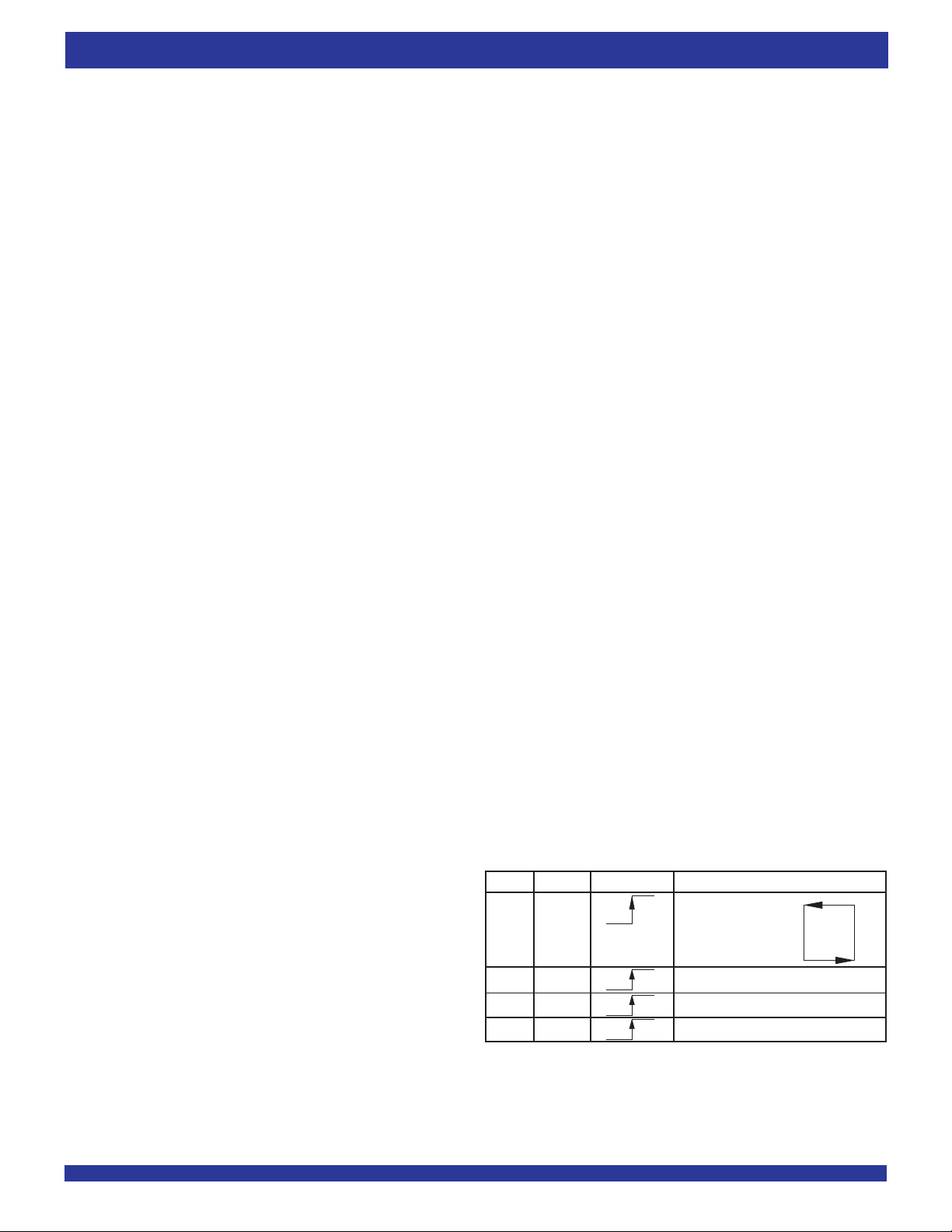
LD WEN1 WCLK Selection
0 0 Empty Offset (LSB)
Empty Offset (MSB)
Full Offset (LSB)
Full Offset (MSB)
0 1 No Operation
1 0 Write Into FIFO
1 1 No Operation
NOTE:
1. For the purposes of this table, WEN2 = V
2. The same selection sequence applies to reading from the registers. REN1 and REN2
are enabled and read is performed on the LOW-to-HIGH transition of RCLK.
IH.
Figure 2. Write Offset Register
5
Page 6
IDT72421/72201/72211/72221/72231/72241/72251 CMOS SyncFIFO™
64 x 9, 256 x 9, 512 x 9, 1,024 x 9, 2,048 x 9, 4,096 x 9 and 8,192 x 9
COMMERCIAL AND INDUSTRIAL
TEMPERATURE RANGES
The contents of the offset registers can be read on the output lines when the
Write Enable 2/Load (WEN2/LD) pin is set LOW and both Read Enables (REN1,
REN2) are set LOW. Data can be read on the LOW-to-HIGH transition of the
Read Clock (RCLK).
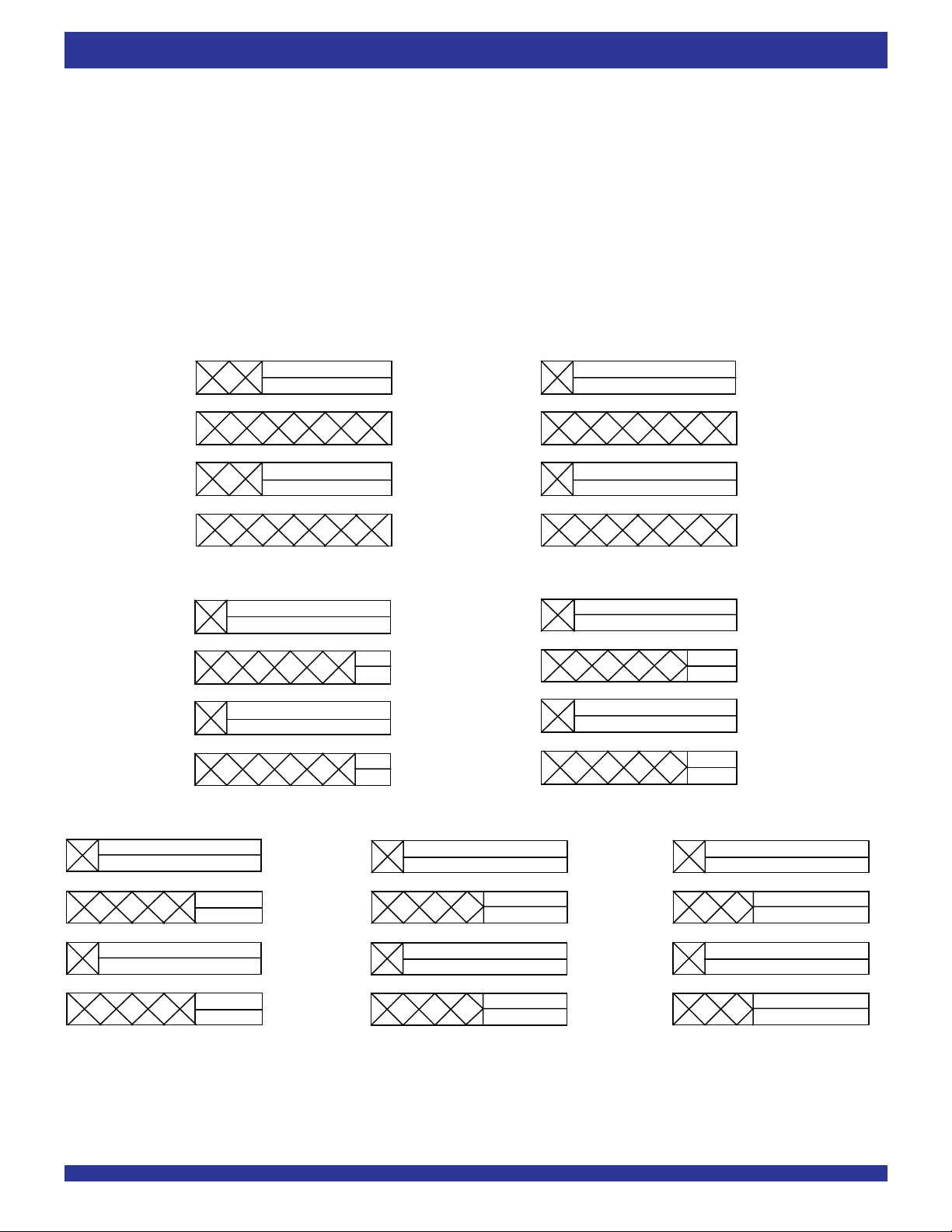
IDT72421 - 64 x 9-BIT IDT72201 - 256 x 9-BIT
86 0
80
80
80
5
Empty Offset (LSB) Reg.
Default Value 007H
65
Full Offset (LSB) Reg.
Default Value 007H
A read and write should not be performed simultaneously to the offset
registers.
87 0
80
80
8
Empty Offset (LSB) Reg.
Default Value 007H
7
Full Offset (LSB) Reg.
Default Value 007H
0
IDT72211 - 512 x 9-BIT
80
7
Empty Offset (LSB)
Default Value 007H
80
80
7
Full Offset (LSB)
Default Value 007H
8
IDT72231 - 2,048 x 9-BIT
87 0
8080
87 0
802
Empty Offset (LSB) Reg.
Default Value 007H
2
(MSB)
000
Full Offset (LSB) Reg.
Default Value 007H
(MSB)
000
1
(MSB)
0
0
1
(MSB)
0
IDT72241 - 4,096 x 9-BIT
80
7
Empty Offset (LSB)
Default Value 007H
3
(MSB)
0000
80
7
Full Offset (LSB)
Default Value 007H
80
3
(MSB)
0000
IDT72221 - 1,024 x 9-BIT
87 0
80
80
80
Empty Offset (LSB) Reg.
Default Value 007H
1
(MSB)
00
7
Full Offset (LSB) Reg.
Default Value 007H
1
(MSB)
00
IDT72251 8,192 x 9-BIT
80
7
Empty Offset (LSB)
Default Value 007H
80
80
7
Full Offset (LSB)
Default Value 007H
80
4
(MSB)
00000
4
(MSB)
00000
2655 drw 05
Figure 3. Offset Register Location and Default Values
6
Page 7
IDT72421/72201/72211/72221/72231/72241/72251 CMOS SyncFIFO™
64 x 9, 256 x 9, 512 x 9, 1,024 x 9, 2,048 x 9, 4,096 x 9 and 8,192 x 9
COMMERCIAL AND INDUSTRIAL
TEMPERATURE RANGES
OUTPUTS:
FULL FLAG (FF)
The Full Flag (FF) will go LOW, inhibiting further write operation, when the
device is full. If no reads are performed after Reset (RS), the Full Flag (FF)
will go LOW after 64 writes for the IDT72421, 256 writes for the IDT72201, 512
writes for the IDT72211, 1,024 writes for the IDT72221, 2,048 writes for the
IDT72231, 4,096 writes for the IDT72241, and 8,192 writes for the IDT72251.
The Full Flag (FF) is synchronized with respect to the LOW-to-HIGH
transition of the Write Clock (WCLK).
EMPTY FLAG (EF)
The Empty Flag (EF) will go LOW, inhibiting further read operations, when
the read pointer is equal to the write pointer, indicating the device is empty.
The Empty Flag (EF) is synchronized with respect to the LOW-to-HIGH
transition of the Read Clock (RCLK).
PROGRAMMABLE ALMOST-FULL FLAG (PAF)
The Programmable Almost-Full flag (PAF) will go LOW when the FIFO
reaches the almost-full condition. If no reads are performed after Reset (RS),
the Programmable Almost-Full flag (PAF) will go LOW after (64-m) writes for the
IDT72421, (256-m) writes for the IDT72201, (512-m) writes for the IDT72211,
(1,024-m) writes for the IDT72221, (2,048-m) writes for the IDT72231, (4,096m) writes for the IDT72241, and (8,192-m) writes for the IDT72251. The offset
“m” is defined in the Full offset registers.
If there is no Full offset specified, the Programmable Almost-Full flag (PAF)
will go LOW at Full-7 words.
The Programmable Almost-Full flag (PAF) is synchronized with respect to
the LOW-to-HIGH transition of the Write Clock (WCLK).
PROGRAMMABLE ALMOST-EMPTY FLAG (PAE)
The Programmable Almost-Empty flag (PAE) will go LOW when the read
pointer is "n+1" locations less than the write pointer. The offset "n" is defined
in the Empty Offset registers. If no reads are performed after Reset the
Programmable Almost-Empty flag (PAE) will go HIGH after "n+1" for the
IDT72421/72201/72211/72221/72231/72241/72251.
If there is no Empty offset specified, the Programmable Almost-Empty flag
(PAE) will go LOW at Empty+7 words.
The Programmable Almost-Empty flag (PAE) is synchronized with respect
to the LOW-to-HIGH transition of the Read Clock (RCLK).
DATA OUTPUTS (Q
0 - Q8)
Data outputs for a 9-bit wide data.
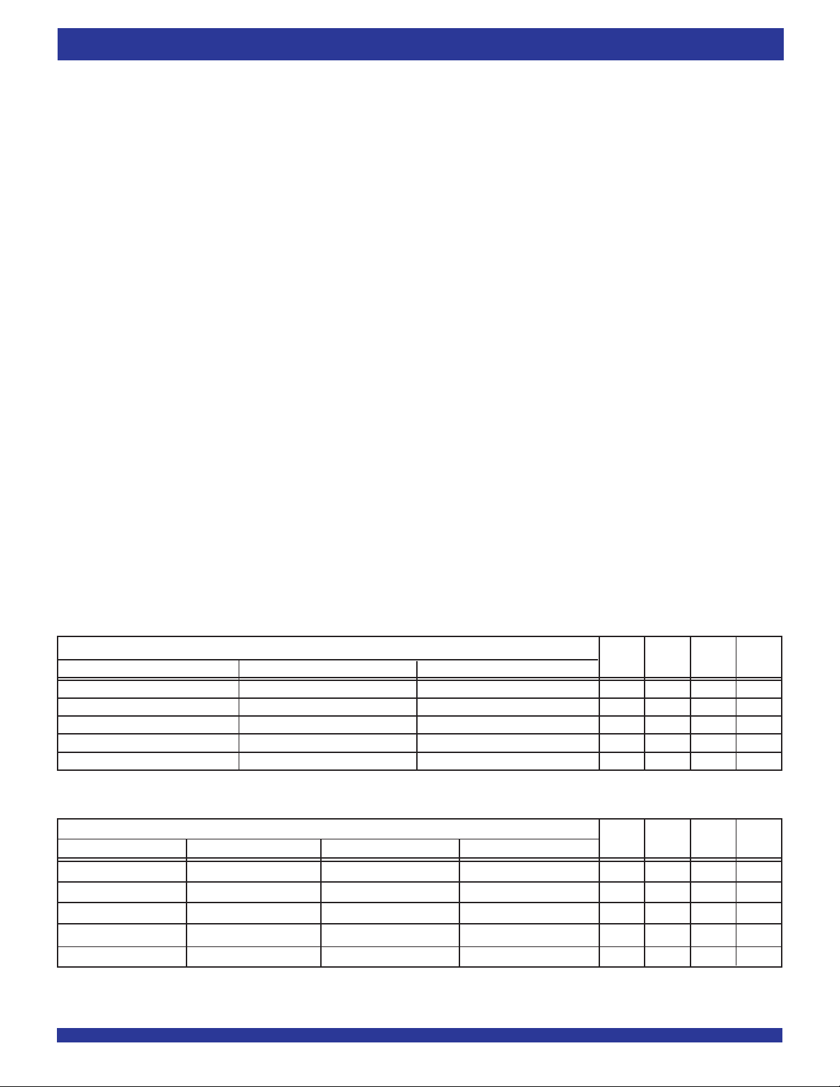
TABLE 1 — STATUS FLAGS
NUMBER OF WORDS IN FIFO
IDT72421 IDT72201 IDT72211 FF PAF PA E EF
000HHLL
(1) (1) (1)
1 to n 1 to n 1 to n H H L H
(n+1) to (64-(m+1)) (n+1) to (256-(m+1)) (n+1) to (512-(m+1)) H H H H
IDT72221 IDT72231 IDT72241 IDT72251 FF PAF PAE EF
1 to n
(n+1) to (1,024-(m+1)) (n+1) to (2,048-(m+1)) (n+1) to (4,096-(m+1)) (n+1) to (8,192-(m+1)) H H H H
(1,024-m)
1,024 2,048 4,096 8,192 L L H H
NOTES:
1. n = Empty Offset (n = 7 default value)
2. m = Full Offset (m = 7 default value)
(2)
to 63 (256-m)
(64-m)
(2)
to 255 (512-m)
(2)
to 511 H L H H
64 256 512 L L H H
NUMBER OF WORDS IN FIFO
00 0 0HHLL
(1)
(2)
to 1,023 (2,048-m)
(1)
1 to n
(2)
to 2,047 (4,096-m)
(1)
1 to n
(2)
to 4,095 (8,192-m)
(1)
1 to n
(2)
to 8,191 H L H H
HHLH
7
Page 8
IDT72421/72201/72211/72221/72231/72241/72251 CMOS SyncFIFO™
64 x 9, 256 x 9, 512 x 9, 1,024 x 9, 2,048 x 9, 4,096 x 9 and 8,192 x 9
t
RS
COMMERCIAL AND INDUSTRIAL
TEMPERATURE RANGES
RS
t
t
RSS
RSR
REN1, REN2
t
t
RSS
RSR
WEN1
t
RSR
WEN2/LD
(1)
t
RSF
t
RSS
EF, PAE
t
RSF
FF, PAF
t
RSF
0
- Q
8
Q
NOTES:
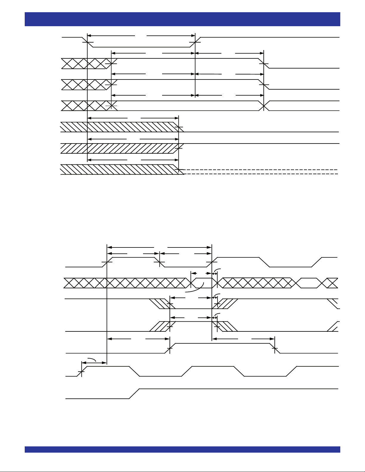
1. Holding WEN2/LD HIGH during reset will make the pin act as a second write enable pin. Holding WEN2/LD LOW during reset will make the pin act as a load enable for the programmable
flag offset registers.
2. After reset, the outputs will be LOW if OE = 0 and tri-state if OE = 1.
3. The clocks (RCLK, WCLK) can be free-running during reset.
OE = 1
OE = 0
(2)
2655 drw 06
Figure 4. Reset Timing
t
CLK
t
CLKH
t
CLKL
WCLK
t
DH
t
ENH
t
ENH
t
WFF
NO OPERATION
NO OPERATION
0
- D
D
WEN1
WEN2/
(If Applicable)
t
DS
8
DATA IN VALID
t
ENS
t
ENS
t
WFF
FF
(1)
t
SKEW1
RCLK
REN1,
REN2
NOTE:
SKEW1 is the minimum time between a rising RCLK edge and a rising WCLK edge for FF to change during the current clock cycle. If the time between the rising edge of RCLK
1. t
and the rising edge of WCLK is less than t
SKEW1, then FF may not change state until the next WCLK edge.
2655 drw 07
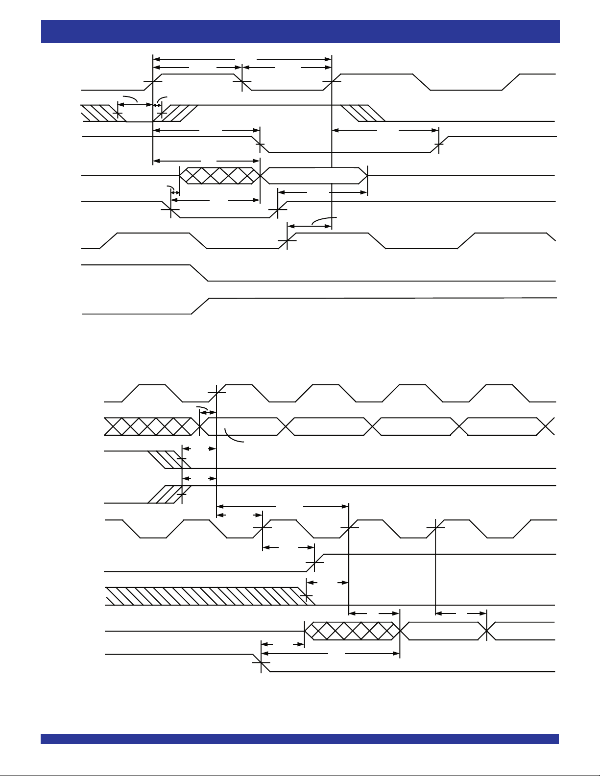
Figure 5. Write Cycle Timing
8
Page 9
IDT72421/72201/72211/72221/72231/72241/72251 CMOS SyncFIFO™
64 x 9, 256 x 9, 512 x 9, 1,024 x 9, 2,048 x 9, 4,096 x 9 and 8,192 x 9
t
t
CLKH
CLK
t
CLKL
RCLK
t
ENS
REN1,
REN2
t
ENH
t
REF
NO OPERATION
EF
t
A
0
- Q
8
Q
t
OLZ
t
OE
VALID DATA
t
OE
WCLK
WEN1
OHZ
SKEW1
t
(1)
t
REF
COMMERCIAL AND INDUSTRIAL
TEMPERATURE RANGES
WEN2
NOTE:
SKEW1 is the minimum time between a rising WCLK edge and a rising RCLK edge for EF to change during the current clock cycle. If the time between the rising edge of RCLK
1. t
and the rising edge of WCLK is less than t
SKEW1, then EF may not change state until the next RCLK edge.
Figure 6. Read Cycle Timing
WCLK
t
DS
D
0
- D
D
WEN1
WEN2
(If Applicable)
RCLK
EF
REN1,
REN2
D
D
t
ENS
1
t
A
8
t
ENS
t
ENS
D0 (First Valid Write)
t
SKEW1
t
FRL
t
REF
(1)
2
t
A
3
2655 drw 08
Q
0
- Q
8
OE
NOTE:
1. When t
SKEW1 ≥ minimum specification, tFRL = tCLK + tSKEW1
SKEW1 < minimum specification, tFRL = 2tCLK + tSKEW1 or tCLK + tSKEW1
When t
The Latency Timings apply only at the Empty Boundary (EF = LOW).
Figure 7. First Data Word Latency Timing
t
OLZ
D
t
0
OE
D
1
2655 drw 09
9
Page 10
IDT72421/72201/72211/72221/72231/72241/72251 CMOS SyncFIFO™
64 x 9, 256 x 9, 512 x 9, 1,024 x 9, 2,048 x 9, 4,096 x 9 and 8,192 x 9
COMMERCIAL AND INDUSTRIAL
TEMPERATURE RANGES
NO WRITE
WCLK
t
SKEW1
D
0
- D
8
t
WFF
t
DS
t
WFF
FF
t
t
ENS
ENH
WEN1
t
t
ENS
ENH
WEN2
(If Applicable)
RCLK
t
REN1,
t
ENS
ENH
t
REN2
t
OE
LOW
0
- Q
8
Q
DATA IN OUTPUT REGISTER
A
NOTE:
1. Only one of the two write enable inputs, WEN1 or WEN2, needs to go inactive to inhibit writes to the FIFO.
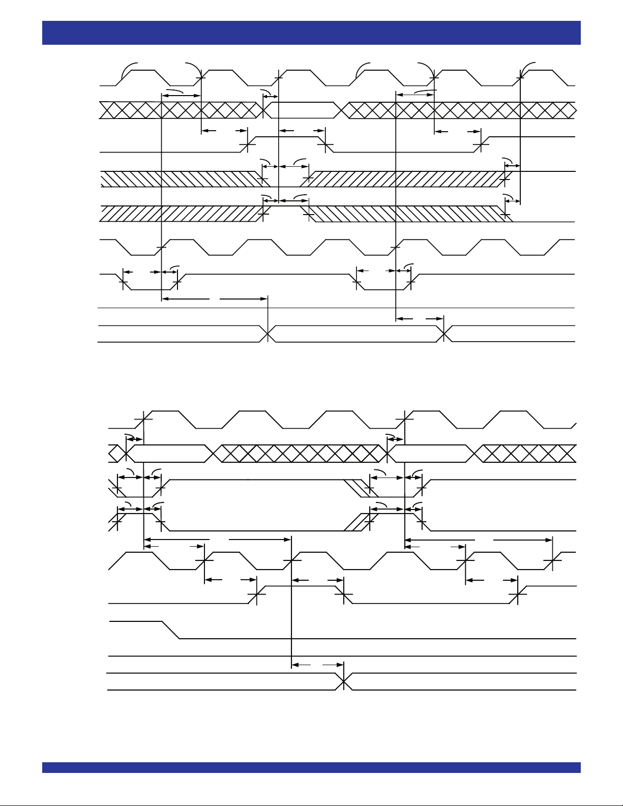
Figure 8. Full Flag Timing
NO WRITE
ENS
t
t
ENH
A
t
SKEW1
t
WFF
NO WRITE
(1)
t
ENS
(1)
t
ENS
NEXT DATA READDATA READ
2655 drw 10
WCLK
t
DS
D
0
- D
8
ENS
t
DATA WRITE 1
t
ENH
WEN1
t
ENS
t
ENH
WEN2
(If Applicable)
t
SKEW1
(1)
t
FRL
RCLK
t
REF
EF
REN1,
REN2
LOW
OE
0
- Q
8
Q
DATA IN OUTPUT REGISTER
NOTE:
1. When t
SKEW1 ≥ minimum specification, tFRL maximum = tCLK + tSKEW1
When tSKEW1 < minimum specification, tFRL maximum = 2tCLK + tSKEW1 or tCLK+ tSKEW1
The Latency Timings apply only at the Empty Boundary (EF = LOW).
Figure 9. Empty Flag Timing
10
t
REF
t
t
DS
DATA WRITE 2
t
ENS
t
ENS
A
t
ENH
t
ENH
t
SKEW1
(1)
t
FFL
t
REF
DATA READ
2655 drw 11
Page 11
IDT72421/72201/72211/72221/72231/72241/72251 CMOS SyncFIFO™
64 x 9, 256 x 9, 512 x 9, 1,024 x 9, 2,048 x 9, 4,096 x 9 and 8,192 x 9
COMMERCIAL AND INDUSTRIAL
TEMPERATURE RANGES
tCLKH tCLKL
(4)
WCLK
tENS
tENH
WEN1
tENS tENH
WEN2
(If Applicable)
tPAF
PAF
Full - (m+1) words in FIFO
(1)
Full - m words in FIFO
tSKEW2
(2)
(3)
tPAF
RCLK
tENS
REN1,
REN2
NOTES:
1. m = PAF offset .
2. 64-m words in FIFO for IDT72421, 256-m words for IDT72201, 512-m words for IDT72211, 1,024-m words for IDT72221, 2,048-m words for IDT72231, 4,096-m words for IDT72241,
and 8,192-m words for IDT72251.
SKEW2 is the minimum time between a rising RCLK edge and a rising WCLK edge for PAF to change during that clock cycle. If the time between the rising edge of RCLK and
3. t
the rising edge of WCLK is less than t
4. If a write is performed on this rising edge of the Write Clock, there will be Full - (m-1) words in the FIFO when PAF goes LOW.
SKEW2, then PAF may not change state until the next WCLK rising edge.
tENH
2655 drw 12
WCLK
WEN1
WEN2
(If Applicable)
PAE
RCLK
REN1,
REN2
t
CLKH
t
ENS
ENS
t
n words in FIFO
t
SKEW2
t
CLKL
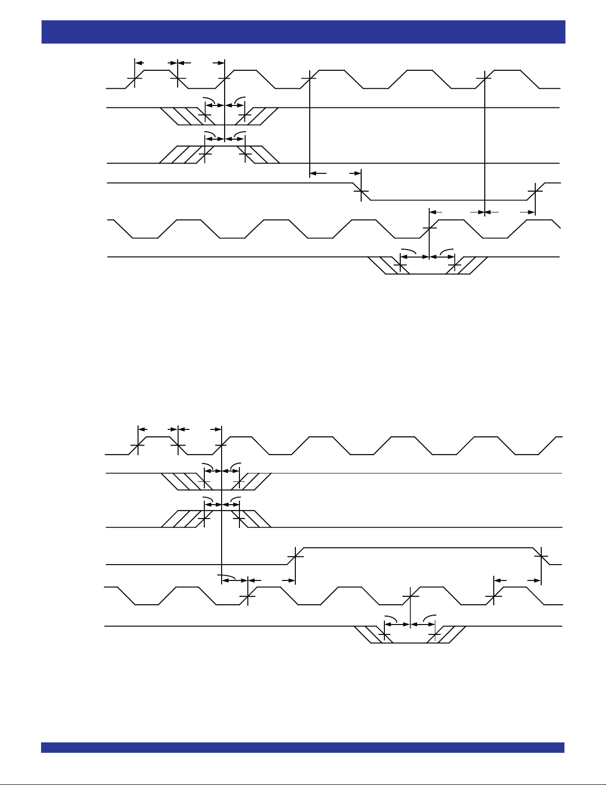
Figure 10. Programmable Full Flag Timing
t
ENH
t
ENH
(1)
(2)
t
PAE
n+1 words in FIFO
t
ENS
t
ENH
t
PAE
(3)
2655 drw 13
NOTES:
1. n = PAE offset.
SKEW2 is the minimum time between a rising WCLK edge and a rising RCLK edge for PAE to change during that clock cycle. If the time between the rising edge of WCLK and
2. t
the rising edge of RCLK is less than t
3. If a read is performed on this rising edge of the Read Clock, there will be Empty + (n-1) words in the FIFO when PAE goes LOW.
SKEW2, then PAE may not change state until the next RCLK rising edge.
Figure 11. Programmable Empty Flag Timing
11
Page 12
IDT72421/72201/72211/72221/72231/72241/72251 CMOS SyncFIFO™
64 x 9, 256 x 9, 512 x 9, 1,024 x 9, 2,048 x 9, 4,096 x 9 and 8,192 x 9
t
CLK
t
t
CLKH
CLKL
WCLK
t
t
ENS
ENH
LD
t
ENS
WEN1
t
DS
0
- D
7
D
PAE OFFSET
(LSB)
t
DH
PAE OFFSET
(MSB)
PAF OFFSET
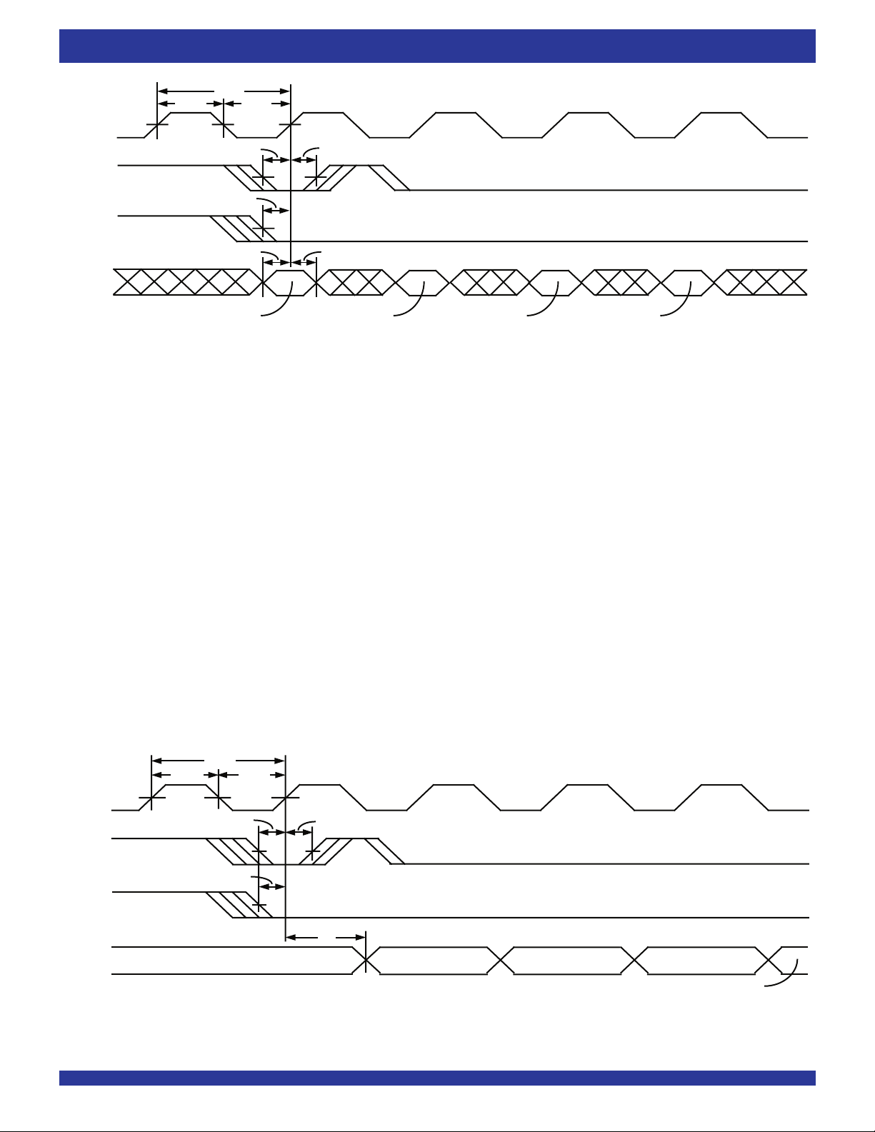
Figure 12. Write Offset Registers Timing
(LSB)
COMMERCIAL AND INDUSTRIAL
PAF OFFSET
(MSB)
TEMPERATURE RANGES
2655 drw 14
RCLK
REN1,
REN2
0
Q
t
CLKH
LD
DATA IN OUTPUT REGISTER
- Q
7
t
CLK
t
ENS
t
ENS
t
CLKL
t
ENH
t
A
EMPTY OFFSET
(LSB)
Figure 13. Read Offset Registers Timing
12
EMPTY OFFSET
(MSB)
FULL OFFSET
(LSB)
FULL OFFSET
(MSB)
2655 drw15
Page 13
IDT72421/72201/72211/72221/72231/72241/72251 CMOS SyncFIFO™
64 x 9, 256 x 9, 512 x 9, 1,024 x 9, 2,048 x 9, 4,096 x 9 and 8,192 x 9
COMMERCIAL AND INDUSTRIAL
TEMPERATURE RANGES
OPERATING CONFIGURATIONS
SINGLE DEVICE CONFIGURATION
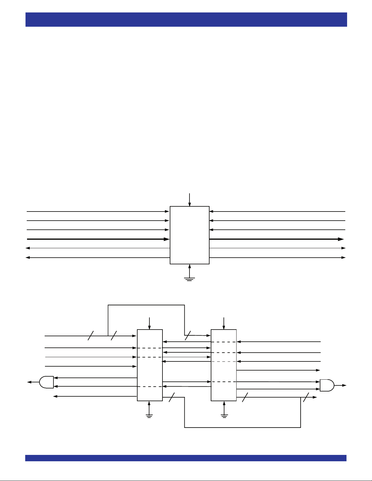
A single IDT72421/72201/72211/72221/72231/72241/72251 may be used
when the application requirements are for 64/256/512/1,024/2,048/4,096/
8,192 words or less. When these FIFOs are in a Single Device Configuration,
the Read Enable 2 (REN2) control input can be grounded (see Figure 14). In
this configuration, the Write Enable 2/Load (WEN2/LD) pin is set LOW at Reset
so that the pin operates as a control to load and read the programmable flag
offsets.
WIDTH EXPANSION CONFIGURATION
Word width may be increased simply by connecting the corresponding input
controls signals of multiple devices. A composite flag should be created for each
of the endpoint status flags (EF and FF). The partial status flags (AE and AF)
can be detected from any one device. Figure 15 demonstrates a 18-bit word
width by using two IDT72421/72201/72211/72221/72231/72241/72251s.
Any word width can be attained by adding additional IDT72421/72201/72211/
72221/72231/72241/72251s.
When these FIFOs are in a Width Expansion Configuration, the Read
Enable 2 (REN2) control input can be grounded (see Figure 15). In this
WRITE CLOCK (WCLK)
WRITE ENABLE 1 (WEN1)
WRITE ENABLE 2/LOAD (WEN2/LD)
FULL FLAG (FF)
PROGRAMMABLE ALMOST-FULL (PAF)
configuration, the Write Enable 2/Load (WEN2/LD) pin is set LOW at Reset so
that the pin operates as a control to load and read the programmable flag offsets.
DEPTH EXPANSION - The IDT72421/72201/72211/72221/72231/72241/
72251 can be adapted to applications when the requirements are for greater
than 64/256/512/1,024/2,048/4,096/8,192 words. The existence of two
enable pins on the read and write port allow depth expansion. The Write
Enable 2/Load pin is used as a second write enable in a depth expansion
configuration thus the Programmable flags are set to the default values. Depth
expansion is possible by using one enable input for system control while the
other enable input is controlled by expansion logic to direct the flow of data. A
typical application would have the expansion logic alternate data access from
one device to the next in a sequential manner. These devices operate in the
Depth Expansion configuration when the following conditions are met:
1. The WEN2/ LD pin is held HIGH during Reset so that this pin operates a
second Write Enable.
2. External logic is used to control the flow of data.
Please see the Application Note "DEPTH EXPANSION OF IDT'S SYNCHRONOUS FIFOs USING THE RING COUNTER APPROACH" for details
of this configuration.
RESET (RS)
IDT
72421
72201
72211
72221
72231
72241
72251
READ CLOCK (RCLK)
READ ENABLE 1 (REN1)
OUTPUT ENABLE (OE)
DATA OUT (Q0 - Q8)DATA IN (D0 - D8)
EMPTY FLAG (EF)
PROGRAMMABLE ALMOST-EMPTY (PAE)
READ ENABLE 2 (REN2)
2655 drw 16
Figure 14. Block Diagram of Single 64 x 9, 256 x 9, 512 x 9, 1,024 x 9, 2,048 x 9, 4,096 x 9, 8,192 x 9 Synchronous FIFO
RESET (RS)
IDT
72421
72201
72211
72221
72231
72241
72251
READ CLOCK (RCLK)
READ ENABLE (REN)
OUTPUT ENABLE (OE)
PROGRAMMABLE (PAE)
EMPTY FLAG (EF) #1
EMPTY FLAG (EF) #2
9
DATA OUT (Q)
18
2655 drw 17
DATA IN (D)
WRITE CLOCK (WCLK)
WRITE ENABLE1 (WEN1)
WRITE ENABLE2/LOAD (WEN2/LD)
PROGRAMMABLE (PAF)
18 9 9
FULL FLAG (FF) #1
FULL FLAG (FF) #2
RESET (RS)
IDT
72421
72201
72211
72221
72231
72241
72251
9
READ ENABLE 2 (REN2)READ ENABLE 2 (REN2)
Figure 15. Block Diagram of 64 x 18, 256 x 18, 512 x 18, 1,024 x 18, 2,048 x 18, 4,096 x 18, 8,192 x 18
Synchronous FIFO Used in a Width Expansion Configuration
13
Page 14
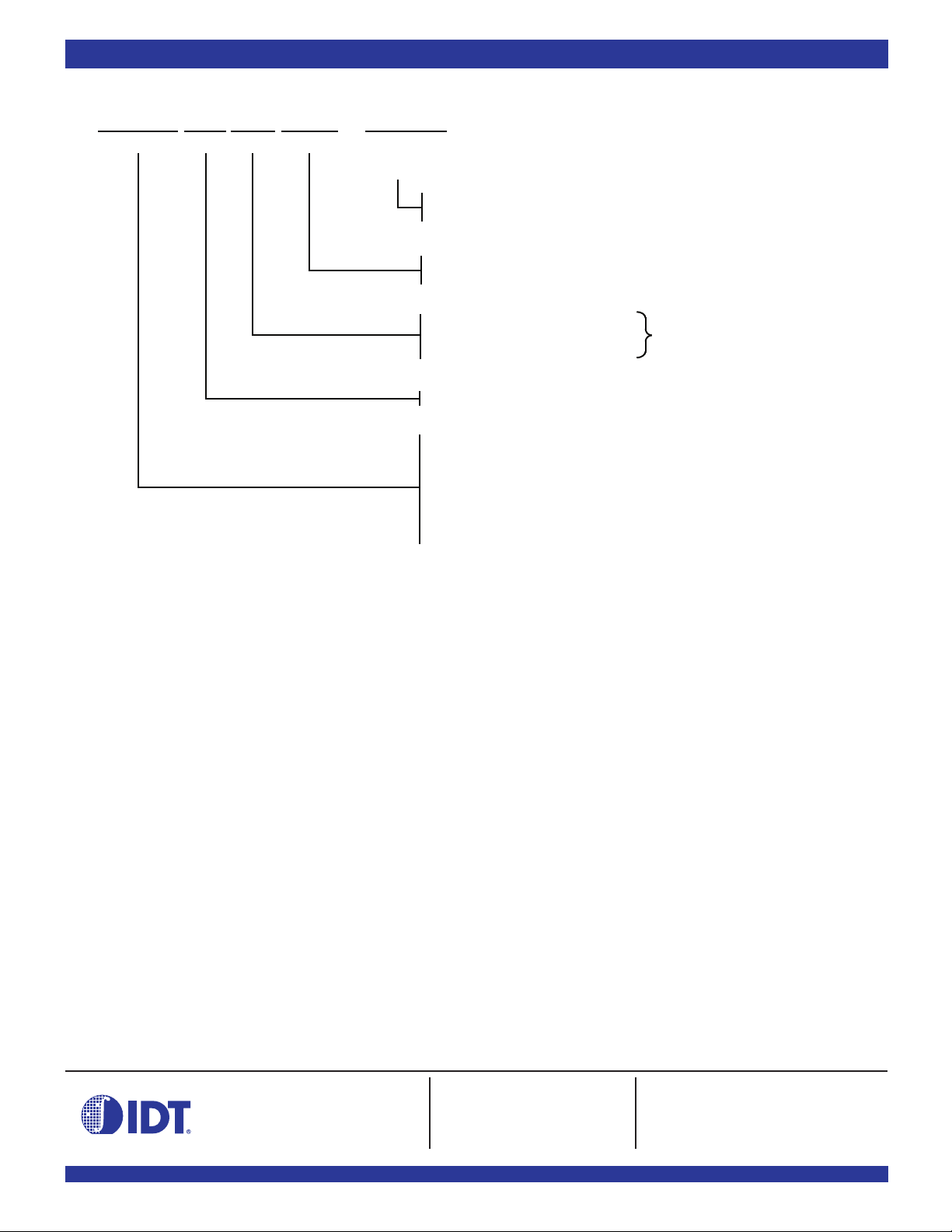
ORDERING INFORMATION
XXXXXIDT
Device Type
XXX X X
Power Speed Package
Process/
Temperature
Range
BLANK
(1)
I
J
PF
10
15
25
L
72421
72201
72211
72221
72231
72241
72251
NOTES:
1. Industrial temperature range product for the 15ns and 25ns speed grades are available as standard product.
Commercial (0°C to +70°C)
Industrial (›40° to +85°C)
Plastic Leaded Chip Carrier (PLCC, J32-1)
Thin Quad Flat Pack (TQFP, PR32-1)
Commercial Only
Commercial & Industrial
Commercial & Industrial
Low Power
64 x 9 SyncFIFO
256 x 9 SyncFIFO
512 x 9 SyncFIFO
1,024 x 9 SyncFIFO
2,048 x 9 SyncFIFO
4,096 x 9 SyncFIFO
8,192 x 9 SyncFIFO
Clock Cycle Time (t
Speed in Nanoseconds
2655 drw18
CLK
)
DATASHEET DOCUMENT HISTORY
10/03/2000 pgs. 2, 3, 4 and 14.
05/01/2001 pgs. 1, 2, 3, 4 and 14.
CORPORATE HEADQUARTERS for SALES: for Tech Support:
2975 Stender Way 800-345-7015 or 408-727-6116 408-330-1753
Santa Clara, CA 95054 fax: 408-492-8674 [email protected]
www.idt.com
14
 Loading...