

Page 1
查询IDT2309供应商
IDT2309
3.3V ZERO DELAY CLOCK BUFFER
COMMERCIAL AND INDUSTRIAL TEMPERATURE RANGES
3.3V ZERO DELAY
CLOCK BUFFER
FEA TURES:
• Phase-Lock Loop Clock Distribution
• 10MHz to 133MHz operating frequency
• Distributes one clock input to one bank of five and one bankd
of four outputs
• Separate output enable for each output bank
• Output Skew < 250ps
• Low jitter <200 ps cycle-to-cycle
• IDT2309-1 for Standard Drive
• IDT2309-1H for High Drive
• No external RC network required
• Operates at 3.3V VDD
• Available in SOIC and TSSOP packages
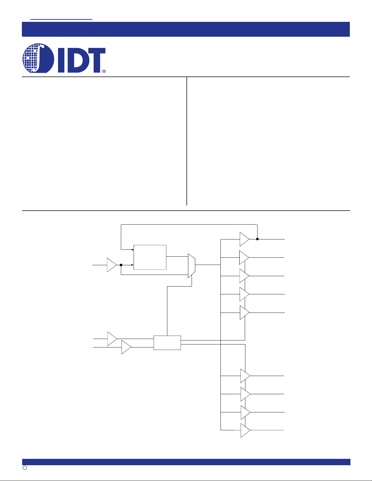
FUNCTIONAL BLOCK DIAGRAM
IDT2309
DESCRIPTION:
The IDT2309 is a high-speed phase-lock loop (PLL) clock buffer,
designed to address high-speed clock distribution applications. The zero
delay is achieved by aligning the phase between the incoming clock and
the output clock, operable within the range of 10 to 133MHz.
The IDT2309 is a 16-pin version of the IDT2305. The IDT2309 accepts
one reference input, and drives two banks of four low skew clocks. The
-1H version of this device operates at up to 133MHz frequency and has
higher drive than the -1 device. All parts have on-chip PLLs which lock
to an input clock on the REF pin. The PLL feedback is on-chip and is
obtained from the CLKOUT pad. In the absence of an input clock, the
IDT2309 enters power down, and the outputs are tri-stated. In this mode,
the device will draw less than 25µA.
The IDT2309 is characterized for both Industrial and Commercial
operation.
NOTE: For new designs, refer to AN-233.
REF
S2
S1
16
1
8
9
PLL
Control
Logic
2
3
14
15
6
7
10
CLKOUT
CLKA1
CLKA2
CLKA3
CLKA4
CLKB1
CLKB2
CLKB3
The IDT logo is a registered trademark of Integrated Device Technology, Inc.
COMMERCIAL AND INDUSTRIAL TEMPERATURE RANGES
2002 Integrated Device Technology, Inc. DSC 5175/5c
1
11
CLKB4
NOVEMBER 2002
Page 2
IDT2309
3.3V ZERO DELAY CLOCK BUFFER
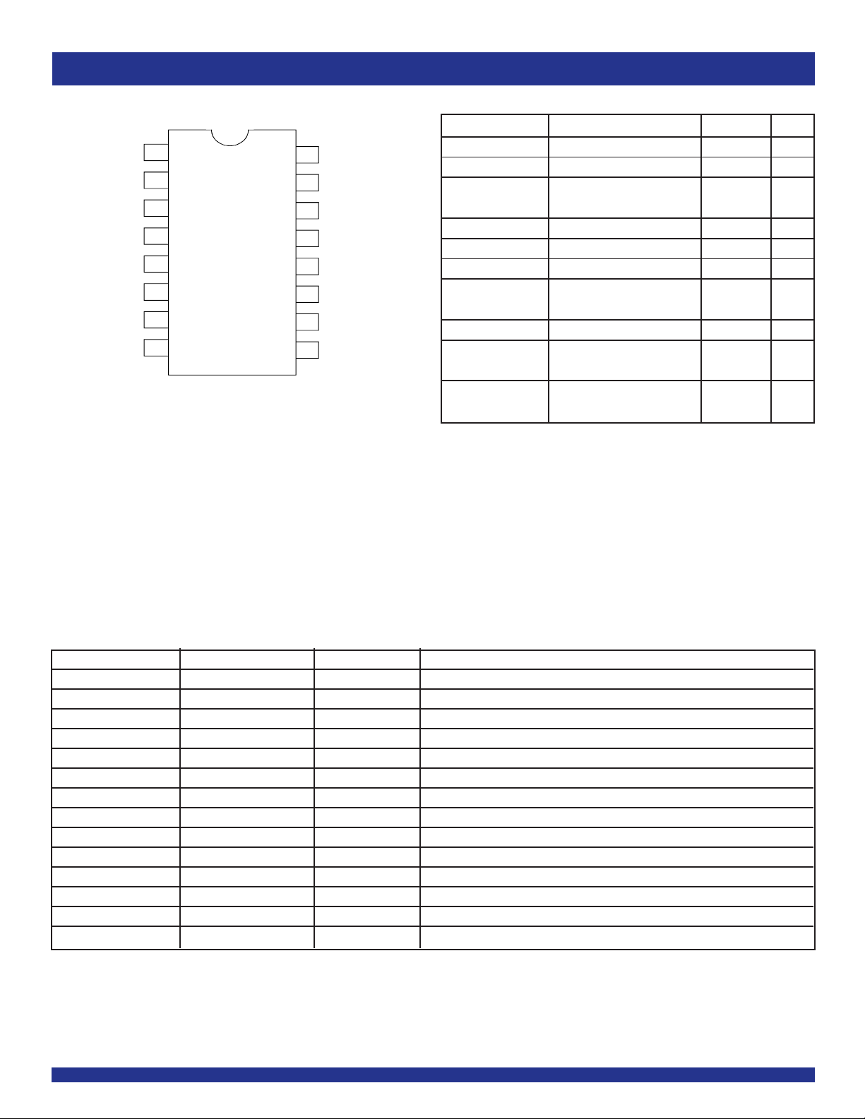
PIN CONFIGURATION
REF
CLKA1
CLKA2
VDD
GND
CLKB1
CLKB2
S2
2
3
4
5
6
7
8
SOIC/ TSSOP
TOP VIEW
APPLICA TIONS:
• SDRAM
• Telecom
• Datacom
• PC Motherboards/Workstations
• Critical Path Delay Designs
161
15
14
13
12
11
10
COMMERCIAL AND INDUSTRIAL TEMPERATURE RANGES
ABSOLUTE MAXIMUM RATINGS
Symbol Rating Max. Unit
CLKOUT
CLKA4
CLKA3
V
DD
GND
CLKB4
CLKB3
9
S1
VDD Supply Voltage Range –0.5 to +4.6 V
(2)
VI
V
I Input Voltage Range –0.5 to V
IIK (VI < 0) Input Clamp Current –5 0 mA
IO (VO = 0 to VDD) Continuous Output Current ±50 mA
VDD or GND Continuous Current ±100 mA
T
A = 55°C Maximum Power Dissipation 0.7 W
(in still air)
TSTG Storage Temperature Range –65 to +150 °C
Operating Commercial Temperature 0 to +70 °C
Temperature Range
Operating Industrial Temperature -40 to +85 °C
Temperature Range
NOTES:
1. Stresses greater than those listed under ABSOLUTE MAXIMUM RATINGS may cause
2. The input and output negative-voltage ratings may be exceeded if the input and output
3. The maximum package power dissipation is calculated using a junction temperature
(3)
permanent damage to the device. This is a stress rating only and functional operation
of the device at these or any other conditions above those indicated in the operational
sections of this specification is not implied. Exposure to absolute maximum rating
conditions for extended periods may affect reliability.
clamp-current ratings are observed.
of 150°C and a board trace length of 750 mils.
Input Voltage Range (REF) –0.5 to +5.5 V
(except REF) VDD+0.5
(1)
PIN DESCRIPTION
Pin Name Pin Number Type Functional Description
(1)
REF
(2)
CLKA1
(2)
CLKA2
VDD 4, 13 PWR 3.3V Supply
GND 5, 12 GND Ground
(2)
CLKB1
(2)
CLKB2
(3)
S2
(3)
S1
(2)
CLKB3
(2)
CLKB4
(2)
CLKA3
(2)
CLKA4
CLKOUT
NOTES:
1. Weak pull down.
2. Weak pull down on all outputs.
3. Weak pull ups on these inputs.
(2)
1 IN Input reference clock, 5 Volt tolerant input
2 Ou t Output clock for bank A
3 Ou t Output clock for bank A
6 Ou t Output clock for bank B
7 Ou t Output clock for bank B
8 IN Select input Bit 2
9 IN Select input Bit 1
1 0 Ou t Output clock for bank B
1 1 Ou t Output clock for bank B
1 4 Ou t Output clock for bank A
1 5 Ou t Output clock for bank A
1 6 Out Output clock, internal feedback on this pin
2
Page 3
IDT2309
3.3V ZERO DELAY CLOCK BUFFER
COMMERCIAL AND INDUSTRIAL TEMPERATURE RANGES
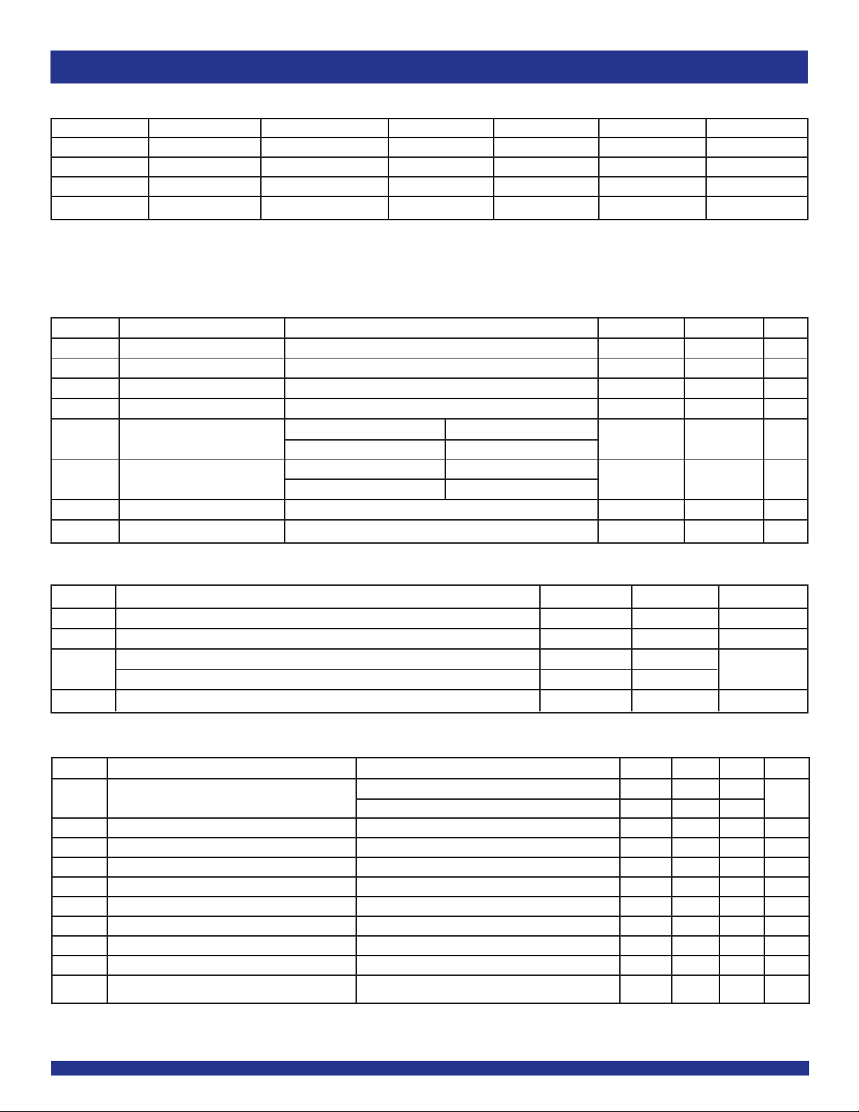
FUNCTION TABLE
S2 S1 CLKA CLKB CLKOUT
(1)
(2)
Output Source PLL Shut Down
L L Tri-State Tri-State Driven PLL N
L H Driven Tri-State Driven PLL N
H L Driven Driven Driven REF Y
H H Driven Driven Driven PLL N
NOTES:
1. H = HIGH Voltage Level.
L = LOW Voltage Level
2. This output is driven and has an internal feedback for the PLL. The load on this ouput can be adjusted to change the skew between the REF and the output.
DC ELECTRICAL CHARACTERISTICS - COMMERCIAL
Symbol Parameter Conditions Min. Max. Unit
VIL Input LOW Voltage Level — 0.8 V
VIH Input HIGH Voltage Level 2 — V
IIL Input LOW Current VIN = 0V — 50 µA
IIH Input HIGH Current VIN = VDD — 100 µA
VOL Output LOW Voltage Standard Drive IOL = 8mA — 0.4 V
High Drive IOL = 12mA (-1H)
VOH Output HIGH Voltage Standard Drive IOH = -8mA 2.4 — V
High Drive IOH = -12mA (-1H)
IDD_PD Power Down Current REF = 0MHz (S2 = S1 = H) — 12 µA
IDD Supply Current Unloaded Outputs at 66.66MHz, SEL inputs at VDD or GND — 32 mA
OPERATING CONDITIONS - COMMERCIAL
Symbol Parameter Min. Max. Unit
VDD Supply Voltage 3 3.6 V
TA Operating Temperature (Ambient Temperature) 0 7 0 °C
CL Load Capacitance < 100MHz — 30 pF
Load Capacitance 100MHz - 133MHz — 10
CIN Input Capacitance — 7 pF
(1,2)
SWITCHING CHARACTERISTICS (2309-1) - COMMERCIAL
Symbol Parameter Conditions Min. Typ. Max. Unit
t1 Output Frequency 10pF Load 1 0 — 13 3 MHz
30pF Load 1 0 — 10 0
Duty Cycle = t2 ÷ t1 Measured at 1.4V, FOUT = 66.66MHz 40 50 60 %
t3 Rise Time Measured between 0.8V and 2V — — 2.5 ns
t4 Fall Time Measured between 0.8V and 2V — — 2.5 ns
t5 Output to Output Skew All outputs equally loaded — — 2 50 ps
t6A Delay, REF Rising Edge to CLKOUT Rising Edge
t6B Delay, REF Rising Edge to CLKOUT Rising Edge
t7 Device-to-Device Skew Measured at VDD/2 on the CLKOUT pins of devices — 0 7 0 0 ps
tJ Cycle-to-Cycle Jitter Measured at 66.66MHz, loaded outputs — — 20 0 ps
t
LOCK PLL Lock Time Stable power supply, valid clock presented on REF pin — — 1 ms
(2)
Measured at VDD/2 — 0 ±350 ps
(2)
Measured at VDD/2 in PLL bypass mode (IDT2309 only) 1 5 8.7 ns
NOTES:
1. REF Input has a threshold voltage of VDD/2.
2. All parameters specified with loaded outputs.
3
Page 4
IDT2309
3.3V ZERO DELAY CLOCK BUFFER
COMMERCIAL AND INDUSTRIAL TEMPERATURE RANGES
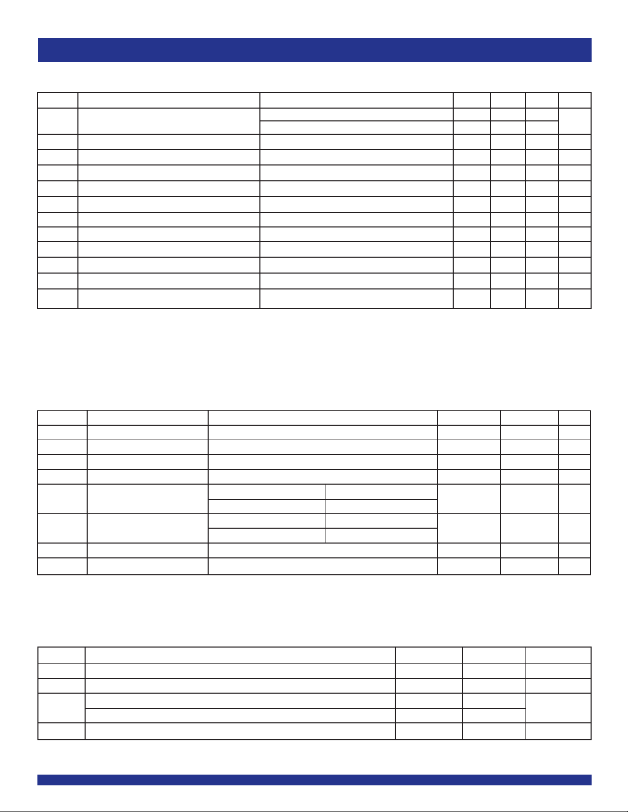
SWITCHING CHARACTERISTICS (2309-1H) - COMMERCIAL
(1,2)
Symbol Parameter Conditions Min. Typ. Max. Unit
1 Output Frequency 10pF Load 10 — 133 MHz
t
30pF Load 1 0 — 10 0
Duty Cycle = t2 ÷ t1 Measured at 1.4V, FOUT = 66.66MHz 40 50 6 0 %
Duty Cycle = t2 ÷ t1 Measured at 1.4V, FOUT <50MHz 45 50 55 %
t3 Rise Time Measured between 0.8V and 2V — — 1. 5 n s
t4 Fall Time Measured between 0.8V and 2V — — 1. 5 n s
t5 Output to Output Skew All outputs equally loaded — — 2 50 ps
t6A Delay, REF Rising Edge to CLKOUT Rising Edge Measured at VDD/2 — 0 ±350 ps
t6B Delay, REF Rising Edge to CLKOUT Rising Edge Measured at VDD/2 in PLL bypass mode (IDT2309 only) 1 5 8.7 ns
t7 Device-to-Device Skew Measured at VDD/2 on the CLKOUT pins of devices — 0 7 0 0 ps
t8 Output Slew Rate Measured between 0.8V and 2V using Test Circuit 2 1 — — V/ns
tJ Cycle-to-Cycle Jitter Measured at 66.66MHz, loaded outputs — — 20 0 ps
tLOCK PLL Lock Time Stable power supply, valid clock presented on REF pin — — 1 ms
NOTES:
1. REF Input has a threshold voltage of VDD/2.
2. All parameters specified with loaded outputs.
DC ELECTRICAL CHARACTERISTICS - INDUSTRIAL
Symbol Parameter Conditions Min. Max. Unit
VIL Input LOW Voltage Level — 0.8 V
VIH Input HIGH Voltage Level 2 — V
IIL Input LOW Current VIN = 0V — 50 µA
IIH Input HIGH Current VIN = VDD — 100 µA
VOL Output LOW Voltage Standard Drive IOL = 8mA — 0.4 V
High Drive IOL = 12mA (-1H)
VOH Output HIGH Voltage Standard Drive IOH = -8mA 2.4 — V
High Drive IOH = -12mA (-1H)
IDD_PD Power Down Current REF = 0MHz (S2 = S1 = H) — 25 µA
IDD Supply Current Unloaded Outputs at 66.66MHz, SEL inputs at VDD or GND — 3 5 mA
OPERATING CONDITIONS - INDUSTRIAL
Symbol Parameter Min. Max. Unit
VDD Supply Voltage 3 3.6 V
TA Operating Temperature (Ambient Temperature) -40 +85 °C
CL Load Capacitance < 100MHz — 30 pF
Load Capacitance 100MHz - 133MHz — 10
CIN Input Capacitance — 7 pF
4
Page 5
IDT2309
3.3V ZERO DELAY CLOCK BUFFER
COMMERCIAL AND INDUSTRIAL TEMPERATURE RANGES
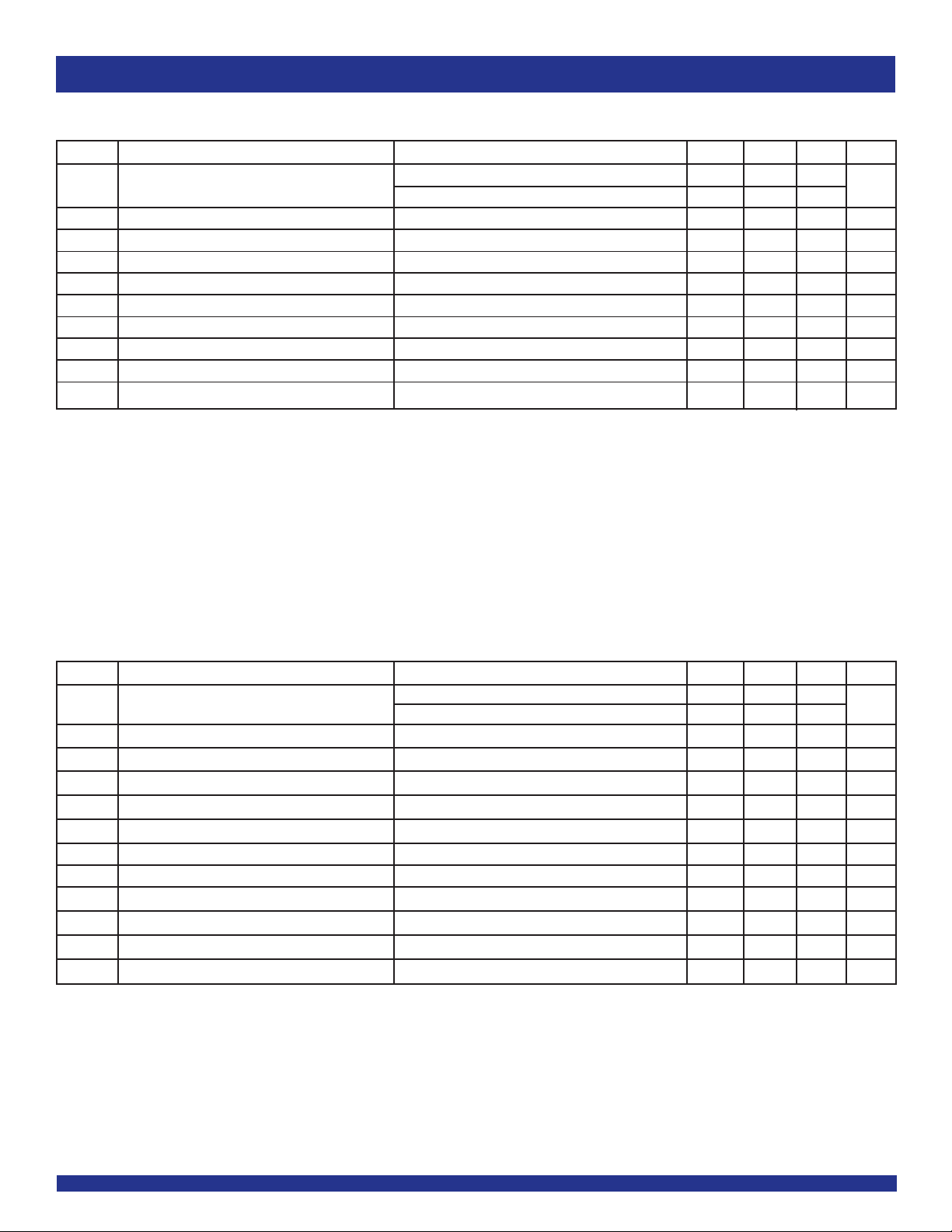
SWITCHING CHARACTERISTICS (2309-1) - INDUSTRIAL
(1,2)
Symbol Parameter Conditions Min. Typ. Max. Unit
t1 Output Frequency 10pF Load 1 0 — 13 3 MHz
30pF Load 1 0 — 10 0
Duty Cycle = t2 ÷ t1 Measured at 1.4V, FOUT = 66.66MHz 40 50 6 0 %
t3 Rise Time Measured between 0.8V and 2V — — 2.5 ns
t4 Fall Time Measured between 0.8V and 2V — — 2.5 ns
t5 Output to Output Skew All outputs equally loaded — — 2 50 ps
t6A Delay, REF Rising Edge to CLKOUT Rising Edge Measured at VDD/2 — 0 ±350 ps
t6B Delay, REF Rising Edge to CLKOUT Rising Edge Measured at VDD/2 in PLL bypass mode (IDT2309 only) 1 5 8.7 ns
t7 Device-to-Device Skew Measured at VDD/2 on the CLKOUT pins of devices — 0 70 0 ps
tJ Cycle-to-Cycle Jitter Measured at 66.66MHz, loaded outputs — — 20 0 ps
t
LOCK PLL Lock Time Stable power supply, valid clock presented on REF pin — — 1 ms
NOTES:
1. REF Input has a threshold voltage of VDD/2.
2. All parameters specified with loaded outputs.
SWITCHING CHARACTERISTICS (2309-1H) - INDUSTRIAL
(1,2)
Symbol Parameter Conditions Min. Typ. Max. Unit
1 Output Frequency 10pF Load 10 — 133 MHz
t
30pF Load 1 0 — 10 0
Duty Cycle = t2 ÷ t1 Measured at 1.4V, FOUT = 66.66MHz 40 50 6 0 %
Duty Cycle = t2 ÷ t1 Measured at 1.4V, FOUT <50MHz 45 50 55 %
t3 Rise Time Measured between 0.8V and 2V — — 1.5 ns
t4 Fall Time Measured between 0.8V and 2V — — 1.5 ns
t5 Output to Output Skew All outputs equally loaded — — 2 50 ps
t6A Delay, REF Rising Edge to CLKOUT Rising Edge Measured at VDD/2 — 0 ±350 ps
t6B Delay, REF Rising Edge to CLKOUT Rising Edge Measured at VDD/2 in PLL bypass mode (IDT2309 only) 1 5 8.7 ns
t7 Device-to-Device Skew Measured at VDD/2 on the CLKOUT pins of devices — 0 70 0 ps
t8 Output Slew Rate Measured between 0.8V and 2V using Test Circuit 2 1 — — V/ns
tJ Cycle-to-Cycle Jitter Measured at 66.66MHz, loaded outputs — — 20 0 ps
tLOCK PLL Lock Time Stable power supply, valid clock presented on REF pin — — 1 ms
NOTES:
1. REF Input has a threshold voltage of VDD/2.
2. All parameters specified with loaded outputs.
5
Page 6
IDT2309
3.3V ZERO DELAY CLOCK BUFFER
COMMERCIAL AND INDUSTRIAL TEMPERATURE RANGES
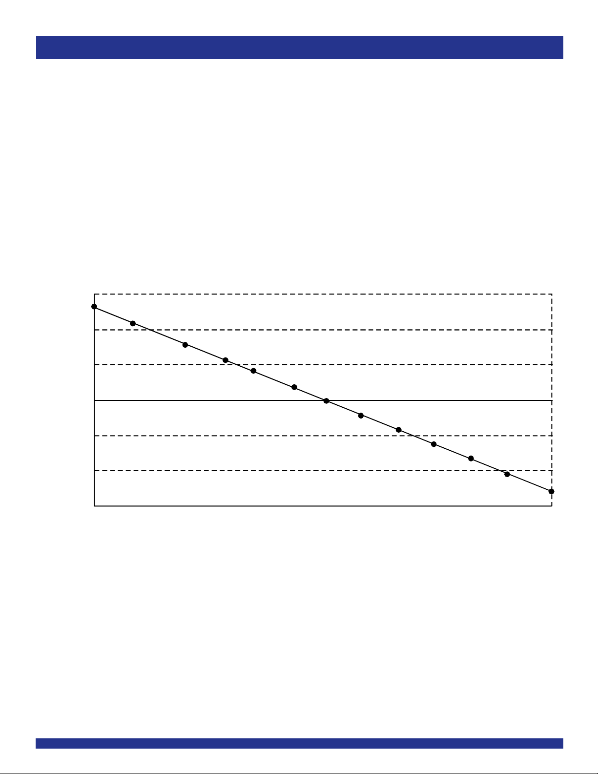
ZERO DELA Y AND SKEW CONTROL
All outputs should be uniformly loaded in order to achieve Zero I/O Delay. Since the CLKOUT pin is the internal feedback for the PLL, its relative
loading can affect and adjust the input/output delay. The Output Load Difference diagram illustrates the PLL's relative loading with respect to the other
outputs that can adjust the Input-Output (I/O) Delay.
For designs utilizing zero I/O Delay, all outputs including CLKOUT must be equally loaded. Even if the output is not used, it must have a capacitive
load equal to that on the other outputs in order to obtain true zero I/O Delay. If I/O Delay adjustments are needed, use the Output Load Difference diagram
to calculate loading differences between the CLKOUT pin and other outputs. For zero output-to-output skew, all outputs must be loaded equally.
REF TO CLKA/CLKB RELAY vs. OUTPUT LOAD DIFFERENCE BETWEEN CLKOUT PIN AND CLKA/CLKB PINS
1500
1000
500
0
-30 -25 -20
-500
-100 0
REF to CLKA/CLKB Delay (ps)
-150 0
OUTPUT LOAD DIFFERENCE BETWEEN CLKOUT PIN AND CLKA/CLKB PINS (pF)
-15
-10
-5
05
10 15 20 25
30
6
Page 7
IDT2309
3.3V ZERO DELAY CLOCK BUFFER
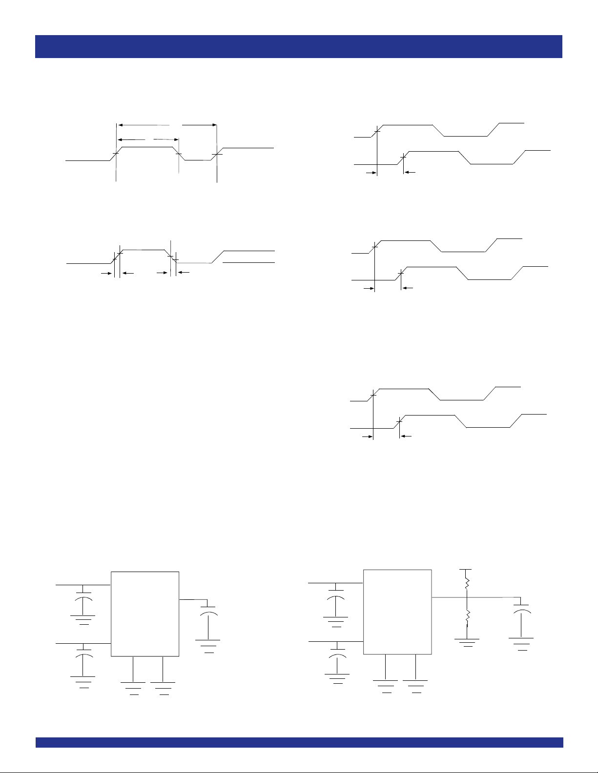
SWITCHING WAVEFORMS
COMMERCIAL AND INDUSTRIAL TEMPERATURE RANGES
Output
t2
1.4V
Duty Cycle Timing
0.8V
t3
2V
All Outputs Rise/Fall Time
1.4V
2V
t1
0.8V
1.4V
t4
3.3V
0V
Output
Output
REF
Output
CLK
OUT
Device 1
CLK
OUT
Device 2
1.4V
1.4V
t5
Output to Output Skew
VDD/2
VDD/2
t6
Input to Output Propagation Delay
DD/2
V
V
t7
DD/2
TEST CIRCUITS
VDD
0.1
µ F
DD
V
0.1
µ F
GND GND
Test Circuit 1 (all Parameters Except t8)
OUTPUTS
CLK
OUT
C
LOAD
0.1
0.1
7
Device to Device Skew
VDD
µ F
µ F
V
GND
OUTPUTS
DD
GND
Test Circuit 2 (t8, Output Slew Rate On -1H Devices)
1KΩ
1KΩ
CLK
OUT
10pF
Page 8
IDT2309
3.3V ZERO DELAY CLOCK BUFFER
COMMERCIAL AND INDUSTRIAL TEMPERATURE RANGES
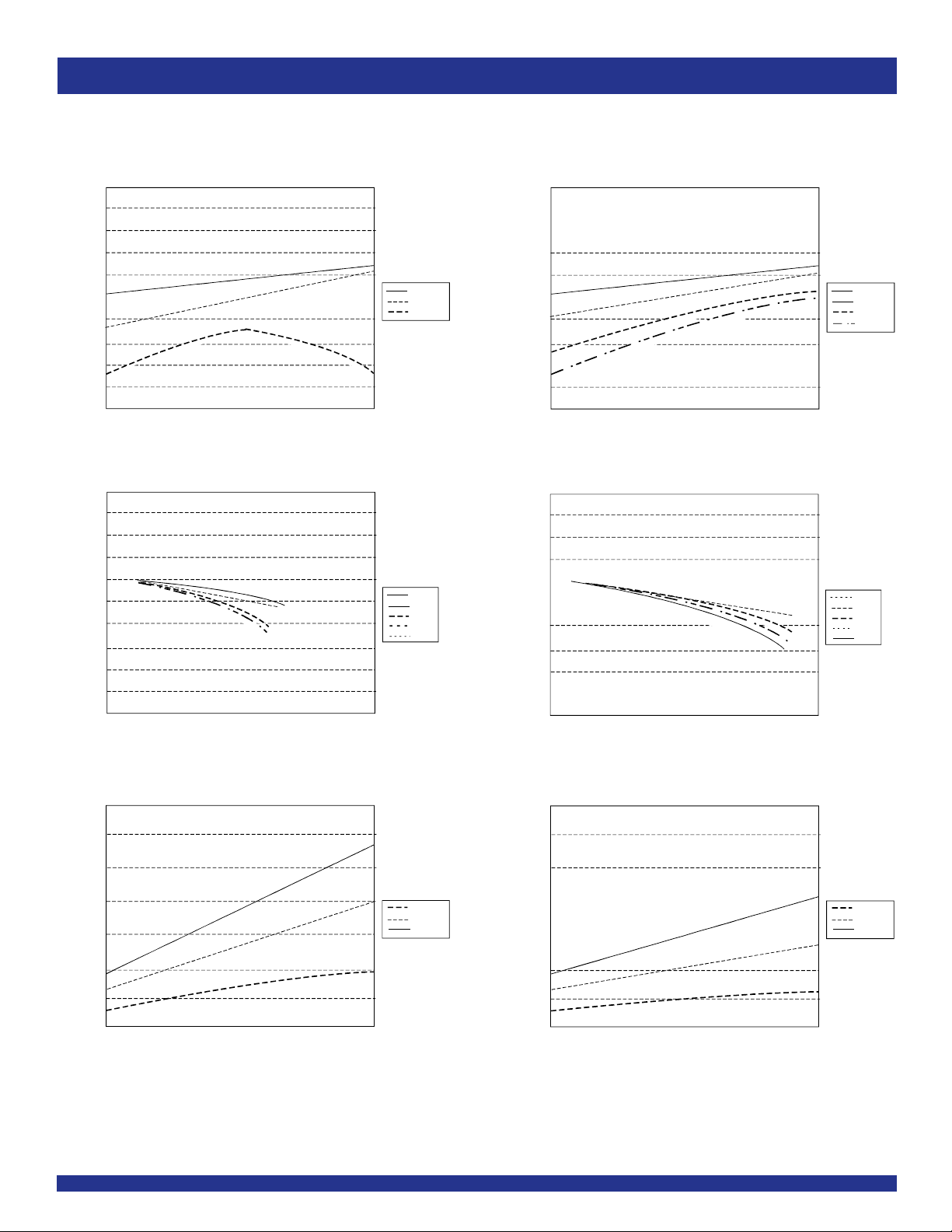
TYPICAL DUTY CYCLE
(for 30pf loads over frequency - 3.3V, 25C)
60
58
56
)
54
%
(
e
52
l
c
y
C
50
y
t
u
D
48
46
44
42
40
3
3.1
(for 30pf loads over temperature - 3.3V)
60
58
56
)
54
%
(
e
l
c
52
y
C
y
50
t
u
D
48
46
44
42
40
20
40
Duty C ycle vs V
3.2
Duty Cycle vs Frequency
60
Frequency (MHz )
DD vs Number of Loaded Outputs
I
140
(for 30pf loads over frequency - 3.3V, 25C)
DD
3.4
3.3
VDD (V)
80 100 120 140
(1)
AND IDD TRENDS
33MHz
66MHz
100MHz
3.5 3.6
-40C
0C
25C
70C
85C
(2)
FOR IDT2309-1
(for 10pF loads over frequency - 3.3V, 25C)
60
58
56
)
54
%
(
e
52
l
c
y
C
50
y
t
u
D
48
46
44
42
40
3
3.1
Duty Cycle vs Frequency
(for 10pF loads over temperature - 3.3V)
60
58
56
)
54
%
(
e
l
c
52
y
C
y
50
t
u
D
48
46
44
42
40
20
40
Frequency (MHz )
DD vs Number of Loaded Outputs
I
140
(for 10pF loads over frequency - 3.3V, 25C)
3.3
DD
3.4
Duty C ycle vs V
3.2
VDD (V)
80 100 120 140
60
3.5 3.6
33MHz
66MHz
100MHz
133MHz
-40C
0C
25C
70C
85C
120
100
80
)
A
m
(
D
60
D
I
40
20
0
02
Number of Loaded Outputs
33MHz
66MHz
100MHz
4
6
8
120
100
80
)
A
m
(
D
60
D
I
40
20
0
02
Number of Loaded Outputs
4
6
NOTES:
1. Duty Cycle is taken from typical chip measured at 1.4V.
2. IDD data is calculated from IDD = ICORE + nCVf, where ICORE is the unloaded current. (n = Number of outputs; C = Capacitance load per output (F);
V = Supply Voltage (V); f = Frequency (Hz))
8
33MHz
66MHz
100MHz
8
Page 9
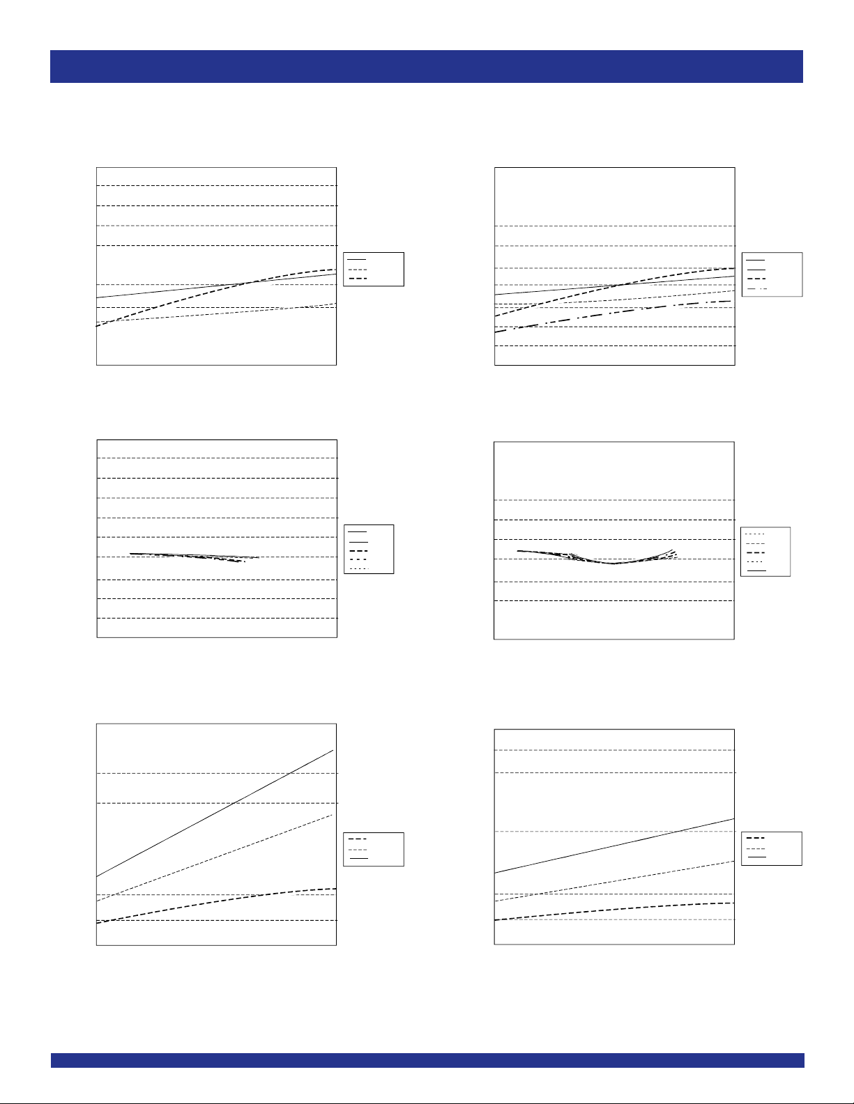
IDT2309
3.3V ZERO DELAY CLOCK BUFFER
COMMERCIAL AND INDUSTRIAL TEMPERATURE RANGES
TYPICAL DUTY CYCLE
(for 30pf loads over frequency - 3.3V, 25C )
60
58
56
)
54
%
(
e
52
l
c
y
C
50
y
t
u
D
48
46
44
42
40
3
3.1
(for 30pf loads over temperature - 3.3V)
60
58
56
)
54
%
(
e
l
c
52
y
C
y
50
t
u
D
48
46
44
42
40
20
40
Duty Cycle vs V
3.2
Duty Cycle vs Frequency
60
Frequency (MHz )
DD vs Number of Loaded Outputs
I
(for 30pf loads over frequency - 3.3V, 25C )
160
140
120
DD
3.4
3.3
VDD (V)
80 100 120 140
(1)
AND IDD TRENDS
33MHz
66MHz
100MHz
3.5 3.6
-40C
0C
25C
70C
85C
(2)
FOR IDT2309-1H
(for 10pF loads over frequency - 3.3V, 25C)
60
58
56
)
54
%
(
e
52
l
c
y
C
50
y
t
u
D
48
46
44
42
40
3
3.1
(for 10pF loads over temperature - 3.3V)
60
58
56
)
54
%
(
e
l
c
52
y
C
y
50
t
u
D
48
46
44
42
40
20
40
Duty Cycle vs V
3.2
Duty Cycle vs Frequency
60
Frequency (MHz)
DD vs Number of Loaded Outputs
I
(for 10pF loads over frequency - 3.3V, 25C)
160
140
120
DD
3.4
3.3
3.5 3.6
VDD (V)
80 100 120 140
33MHz
66MHz
100MHz
133MHz
-40C
0C
25C
70C
85C
100
80
)
A
m
(
D
60
D
I
40
20
0
02
Number of Loaded Outputs
33MHz
66MHz
100MHz
4
6
8
100
80
)
A
m
(
D
60
D
I
40
20
0
02
Number of Loaded Outputs
33MHz
66MHz
100MHz
4
6
8
NOTES:
1. Duty Cycle is taken from typical chip measured at 1.4V.
2. IDD data is calculated from IDD = ICORE + nCVf, where ICORE is the unloaded current. (n = Number of outputs; C = Capacitance load per output (F); V = Supply Voltage (V);
f = Frequency (Hz))
9
Page 10
IDT2309
3.3V ZERO DELAY CLOCK BUFFER
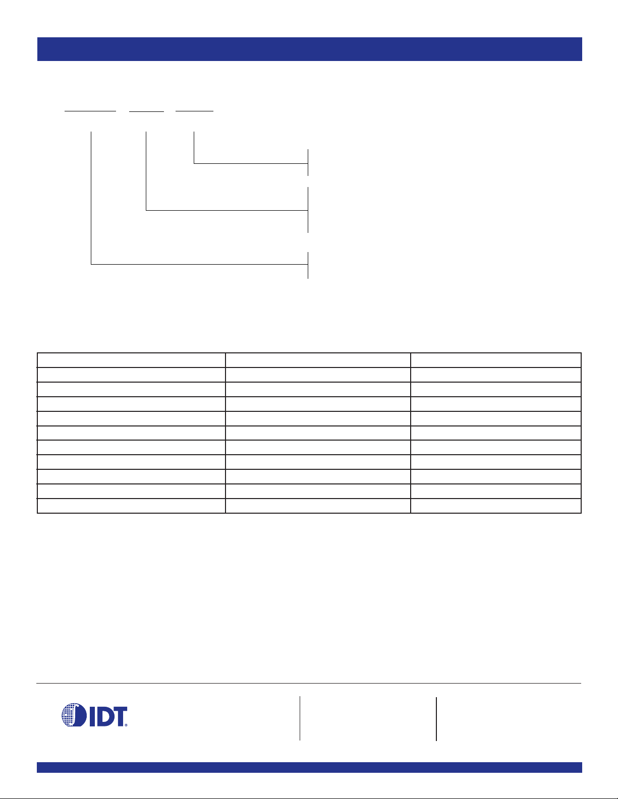
ORDERING INFORMATION
XXXXX XX X
IDT
Device Type
Package Process
COMMERCIAL AND INDUSTRIAL TEMPERATURE RANGES
o
Blank
I
Commercial (0
Industrial (-40
C to +70oC)
o
C to +85oC)
DC
DCG
PG
PGG
2309-1
2309-1H
Ordering Code Package Type Operating Range
IDT2309-1DC 16-Pin SOIC Commercial
IDT2309-1DCI 16-Pin SOIC Industrial
IDT2309-1HDC 16-Pin SOIC Commercial
IDT2309-1HDCG 16-Pin SOIC Commercial
IDT2309-1HDCI 16-Pin SOIC Industrial
IDT2309-1HDCGI 16-Pin SOIC Industrial
IDT2309-1HPG 16-Pin TSSOP Commercial
IDT2309-1HPGG 16-Pin TSSOP Commercial
IDT2309-1HPGI 16-Pin TSSOP Industrial
IDT2309-1HPGGI 16-Pin TSSOP Industrial
Small Outline
SOIC - Green
Thin Shrink Small Outline Package
TSSOP - Green
Zero Delay Clock Buffer
High Drive Output
CORPORATE HEADQUARTERS for SALES: for Tech Support:
2975 Stender Way 800-345-7015 or 408-727-6116 [email protected]
Santa Clara, CA 95054 fax: 408-492-8674 (408) 654-6459
www.idt.com
10
 Loading...