

Page 1
ICX059AK
A
A
For the availability of this product, please contact the sales office.
1/3-inch CCD Image Sensor for PAL Color Camera
Description
The ICX059AK is an interline CCD solid-state image
sensor suitable for PAL color video cameras. High
resolution is achieved through the use of Ye, Cy, Mg,
and G complementary color mosaic filters. At the
same time, high sensitivity and low dark current are
achieved through the adoption of HAD (HoleAccumulation Diode) sensors.
This chip features a field period readout system and
an electronic shutter with variable charge-storage time.
Features
• High resolution, high sensitivity and low dark current
• Continuous variable-speed shutter
1/50s (Typ.), 1/120s to 1/10000s
• Low smear
• Excellent antiblooming characteristics
• Ye, Cy, Mg, and G complementary color mosaic filters on chip
• Horizontal register: 5V drive
• Reset gate: 5V drive
16 pin DIP (Plastic)
V
3
Pin 9
Pin 1
AAA
AAA
H
2
12
40
Device Structure
• Optical size: 1/3-inch format
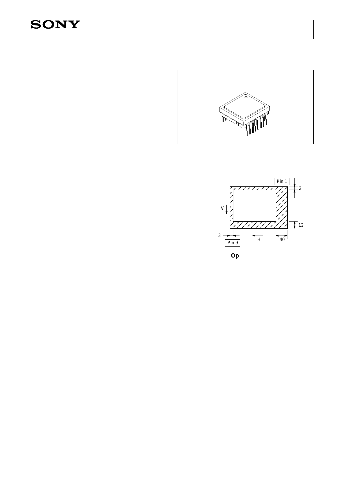
• Number of effective pixels: 752 (H) × 582 (V) approx. 440K pixels
• Number of total pixels: 795 (H) × 596 (V) approx. 470K pixels
• Interline CCD image sensor
• Chip size: 6.00mm (H) × 4.96mm (V)
• Unit cell size: 6.50µm (H) × 6.25µm (V)
• Optical black: Horizontal (H) direction: Front 3 pixels, rear 40 pixels
Vertical (V) direction: Front 12 pixels, rear 2 pixels
• Number of dummy bits: Horizontal 22
Vertical 1 (even field only)
• Substrate material: Silicon
Optical black position
(Top View)
Sony reserves the right to change products and specifications without prior notice. This information does not convey any license by
any implication or otherwise under any patents or other right. Application circuits shown, if any, are typical examples illustrating the
operation of the devices. Sony cannot assume responsibility for any problems arising out of the use of these circuits.
– 1 –
E91Y29B5Y-PS
Page 2
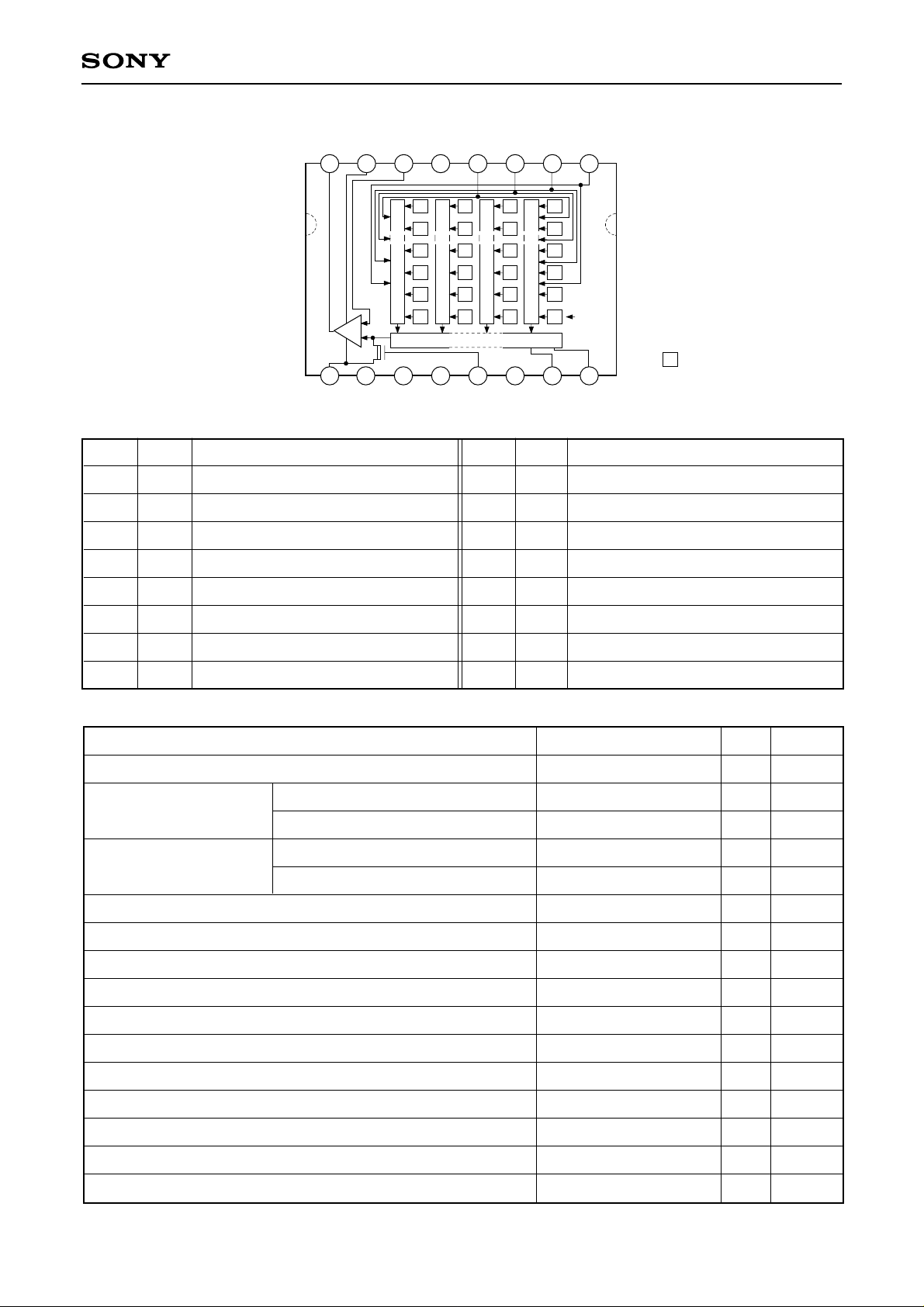
Block Diagram and Pin Configuration
(Top View)
OUT
V
8
ICX059AK
2
5
GND
1
Vφ
Vφ
4
3
SS
GG
V
V
6
7
4
3
Vφ
Vφ
1
2
Pin Description
Pin No.
1
2
3
4
5
6
7
Symbol
Vφ4
Vφ3
Vφ2
Vφ1
GND
VGG
VSS
9
10
DD
V
GND
Description
Vertical register transfer clock
Vertical register transfer clock
Vertical register transfer clock
Vertical register transfer clock
GND
Output amplifier gate bias
Output amplifier source
Cy
Ye
Cy
Mg
Cy
GMgGMg
Cy
Vertical register
Mg G Mg G
Horizontal register
12
11
L
V
SUB
Mg G
G
Cy Ye
Ye
Ye Cy Ye
13
14 15
1
RG
LHφ
Pin No.
9
10
11
12
13
14
15
Symbol
VDD
GND
SUB
VL
RG
LHφ1
Hφ1
Ye
Note)
Note) :Photo sensor
16
2
1
Hφ
Hφ
Description
Output amplifier drain supply
GND
Substrate (Overflow drain)
Protective transistor bias
Reset gate clock
Horizontal register final stage transfer clock
Horizontal register transfer clock
8
VOUT
Signal output
Absolute Maximum Ratings
Item Ratings Unit Remarks
Substrate voltage SUB – GND
VDD, VOUT, VSS – GND
Supply voltage
VDD, VOUT, VSS – SUB
Vφ1, Vφ2, Vφ3, Vφ4 – GND
Vertical clock input voltage
Vφ1, Vφ2, Vφ3, Vφ4 – SUB
Voltage difference between vertical clock input pins
Voltage difference between horizontal clock input pins
Hφ1, Hφ2 – Vφ4
Hφ1, Hφ2, LHφ1, RG, VGG – GND
Hφ1, Hφ2, LHφ1, RG, VGG – SUB
VL – SUB
Vφ1, Vφ2, Vφ3, Vφ4, VDD, VOUT – VL
RG – VL
16
Hφ2
Horizontal register transfer clock
–0.3 to +55
–0.3 to +18
–55 to +10
–15 to +20
to +10
to +15
to +17
–17 to +17
–10 to +15
–55 to +10
–65 to +0.3
–0.3 to +30
–0.3 to +24
V
V
V
V
V
V
V
V
V
V
V
V
V
∗1
VGG, VSS, Hφ1, Hφ2, LHφ1 – VL
Storage temperature
Operating temperature
∗1
+27V (Max.) when clock width < 10µs, clock duty factor < 0.1%.
– 2 –
–0.3 to +20
–30 to +80
–10 to +60
V
°C
°C
Page 3
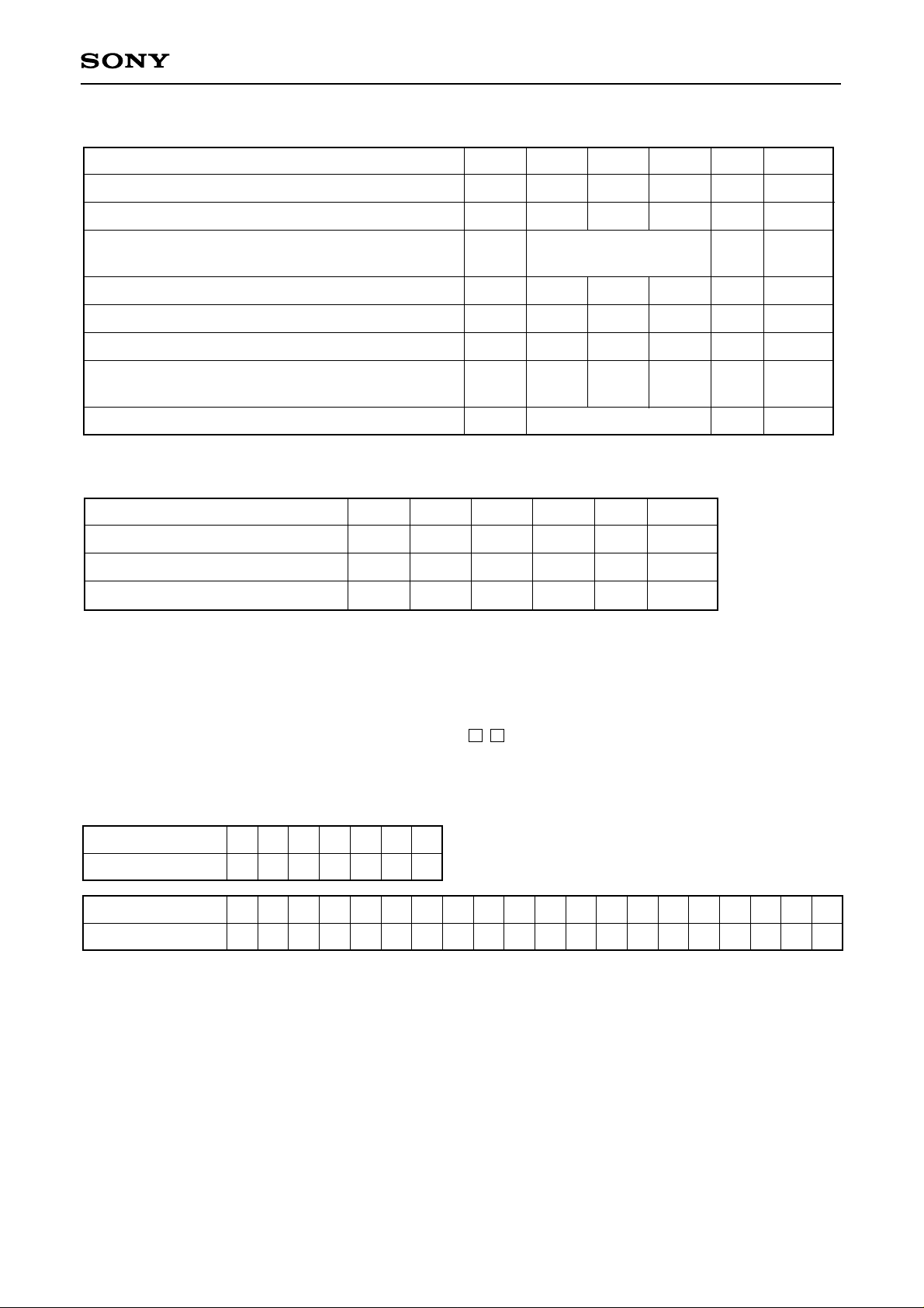
Bias Conditions
ICX059AK
Item
Output amplifier drain voltage
Output amplifier gate voltage
Output amplifier source
Substrate voltage adjustment range
Fluctuation range after substrate voltage adjustment
Reset gate clock voltage adjustment range
Fluctuation range after reset gate clock voltage
adjustment
Protective transistor bias
DC Characteristics
Item
Output amplifier drain current
Input current
Input current
Symbol Min. Typ. Max. Unit Remarks
IDD
IIN1
IIN2
Symbol Min. Typ. Max. Unit Remarks
%
%
V
V
±5%
∗1
V
∗1 ∗6
V
VDD
VGG
VSS
VSUB
∆VSUB
VRGL
∆VRGL
VL
5
14.55
3.8
Grounded with
820Ω resistor
9.0
–3
1.0
–3
1
10
15.0
4.2
∗2
mA
µA
µA
15.45
4.65
18.5
+3
4.0
+3
∗3
∗4
∗1
Indications of substrate voltage (VSUB) · reset gate clock voltage (VRGL) setting value.
The setting values of substrate voltage and reset gate clock voltage are indicated on the back of the image
sensor by a special code. Adjust substrate voltage (VSUB) and reset gate clock voltage (VRGL) to the
indicated voltage. Fluctuation range after adjustment is ±3%.
VSUB code one character indication
VRGL code one character indication ↑↑
VRGL code VSUB code
Code and optimal setting correspond to each other as follows.
VRGL code
Optimal setting
VSUB code
Optimal setting
1
3
2
45
1.0 1.5 2.0 2.5 3.0 3.5 4.0
EfG
9.0 9.5
hJKL
10.0 10.5 11.0 11.5 12.012.5 13.0 13.5 14.0 14.5 15.0 15.516.0 16.5 17.0 17.5 18.0 18.5
6
7
m
NP
Q
R
S
UVWX
T
<Example> “5L” → VRGL = 3.0V
VSUB = 12.0V
∗2
VL setting is the VVL voltage of the vertical transfer clock waveform.
∗3
1) Current to each pin when 18V is applied to VDD, VOUT, Vss and SUB pins, while pins that are not tested
are grounded.
2) Current to each pin when 20V is applied sequentially to Vφ1, Vφ2, Vφ3 and Vφ4 pins, while pins that are
not tested are grounded. However, 20V is applied to SUB pin.
3) Current to each pin when 15V is applied sequentially to RG, LHφ1, Hφ1, Hφ2 and VGG pins, while pins
that are not tested are grounded. However, 15V is applied to SUB pin.
4) Current to VL pin when 30V is applied to Vφ1, Vφ2, Vφ3, Vφ4, VDD and VOUT pins or when, 24V is applied
to RG pin or when, 20V is applied to VGG, Vss, Hφ1, Hφ2 and LHφ1 pins, while VL pin is grounded.
However, GND and SUB pins are left open.
∗4
Current to SUB pin when 55V is applied to SUB pin, while pins that are not tested are grounded.
– 3 –
Y
Z
Page 4
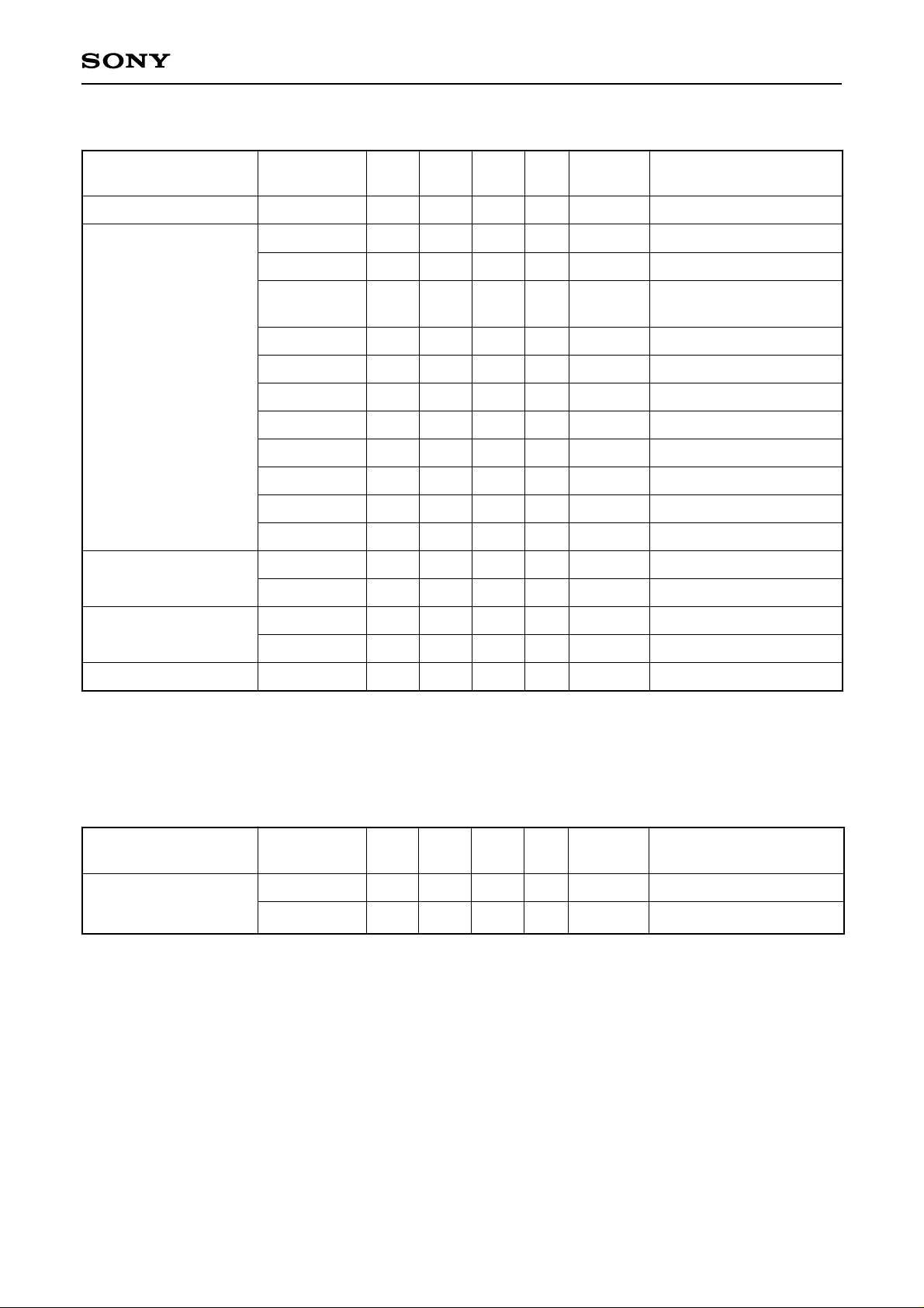
Clock Voltage Conditions
ICX059AK
Item
Readout clock voltage
Vertical transfer clock
voltage
Horizontal transfer
clock voltage
Reset gate clock
voltage
Symbol Min.
VVT
VVH1, VVH2
VVH3, VVH4
VVL1, VVL2,
VVL3, VVL4
VφV
I VVH1 – VVH2 I
VVH3 – VVH
VVH4 – VVH
VVHH
VVHL
VVLH
VVLL
VφH,VφLH
VHL,VLHL
VφRG
VRGLH – VRGLL
14.55
–0.05
–0.2
–9.0
7.8
–0.25
–0.25
4.75
–0.05
4.5
Typ. Max.
15.0
–8.5
0
0
8.5
15.45
0.05
0.05
–8.0
9.05
0.1
0.1
0.1
0.5
0.5
0.5
0.5
5.0
5.0
5.25
0
0.05
5.5
0.8
Unit
V
V
V
V
V
V
V
V
V
V
V
V
V
V
V
V
Waveform
diagram
1
2
2
2
2
2
2
2
2
2
2
2
3
3
4
4
Remarks
VVH = (VVH1 + VVH2)/2
VVL = (VVL3 + VVL4)/2
VφV = VVHn – VVLn (n = 1 to 4)
High-level coupling
High-level coupling
Low-level coupling
Low-level coupling
∗5
∗5
∗6
Low-level coupling
Substrate clock voltage
∗5
The horizontal final stage transfer clock input pin LHφ1 is connected to the horizontal transfer clock input
VφSUB
22.5
23.5
24.5
V
5
pin Hφ1.
∗6
The reset gate clock voltage need not be adjusted when reset gate clock is driven when the specifications
are as given below. In this case, the reset gate clock voltage setting indicated on the back of the image
sensor has not significance.
Item
Reset gate clock
voltage
Symbol
VRGL
VφRG
Min.
–0.2
8.5
Typ.
0
9.0
Max.
0.2
9.5
Unit
V
V
Waveform
diagram
4
4
Remarks
– 4 –
Page 5
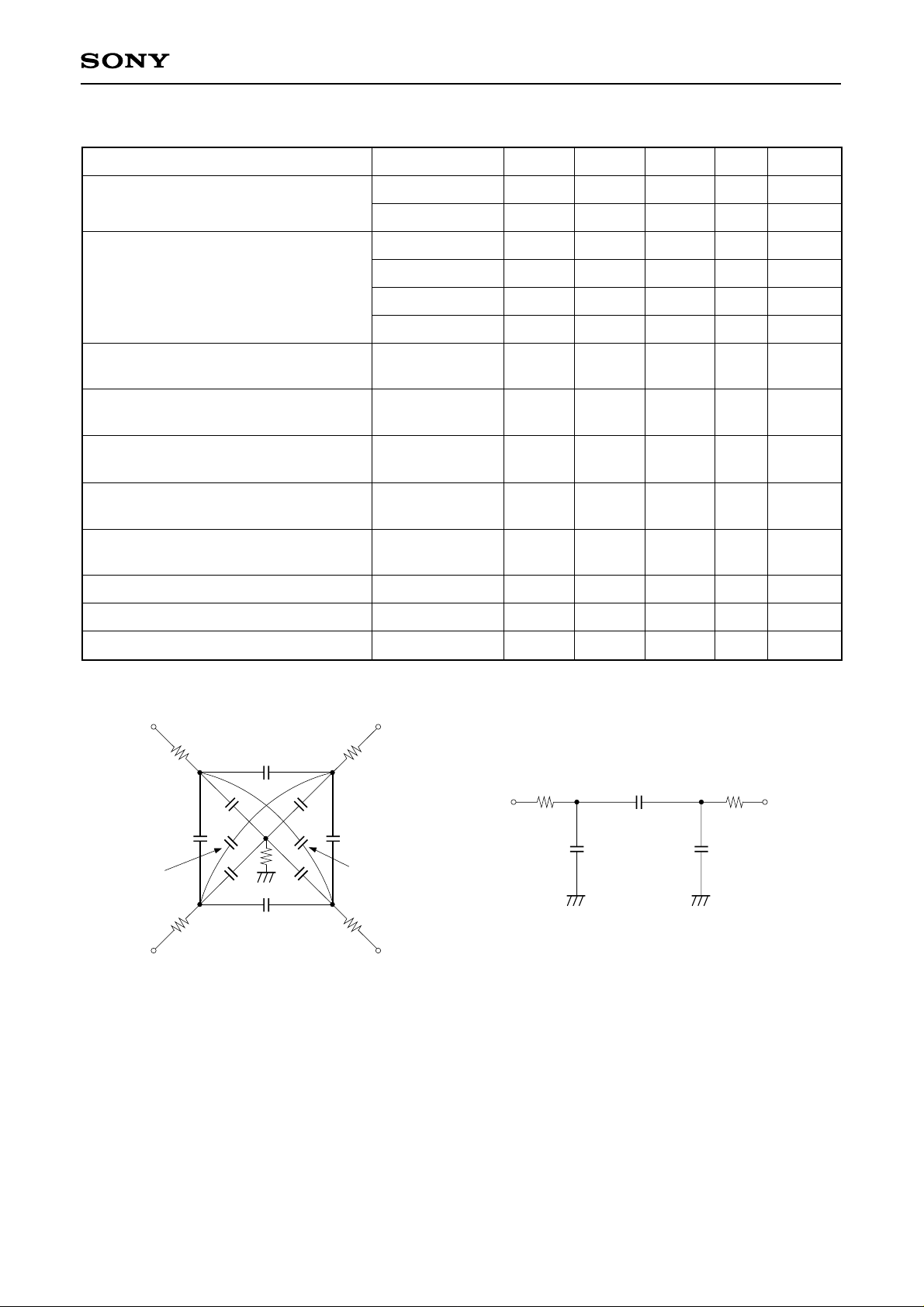
Clock Equivalent Circuit Constant
ICX059AK
Item
Capacitance between vertical transfer
clock and GND
Capacitance between vertical transfer
clocks
Capacitance between horizontal
transfer clock and GND
Capacitance between horizontal
transfer clocks
Capacitance between horizontal final
stage transfer clock and GND
Capacitance between reset gate clock
and GND
Capacitance between substrate clock
and GND
Vertical transfer clock series resistor
Symbol Min. Typ. Max. Unit Remarks
CφV1, CφV3
CφV2, CφV4
CφV12, CφV34
CφV23, CφV41
CφV13
CφV24
CφH1, CφH2
CφHH
CφLH
CφRG
CφSUB
R1, R2, R3, R4
1000
560
470
390
180
100
47
51
8
8
270
80
pF
pF
pF
pF
pF
pF
pF
pF
pF
pF
pF
Ω
Vertical transfer clock ground resistor
Horizontal transfer clock series resistor
Vφ1
R1
CφV41
CφV24
R4
Vφ4 Vφ3
CφV12
CφV1 CφV2
RGND
CφV4 CφV3
CφV34
R2
CφV23
CφV13
R3
Vφ2
RGND
RφH
Hφ1
15
15
RφH RφH
CφHH
CφH1
CφH2
Vertical transfer clock equivalent circuit Horizontal transfer clock equivalent circuit
Ω
Ω
Hφ2
– 5 –
Page 6
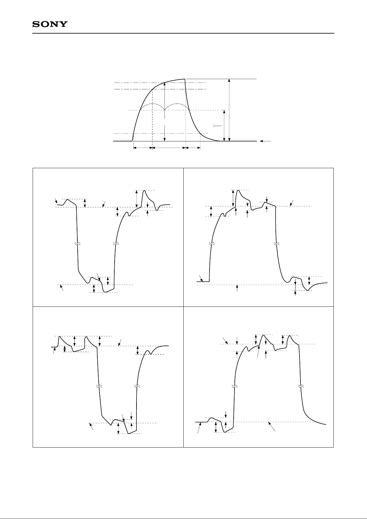
Drive Clock Waveform Conditions
(1) Readout clock waveform
100%
90%
ICX059AK
II II
φM
VVT
10%
0%
tr twh tf
(2) Vertical transfer clock waveform
Vφ1 Vφ3
VVH1
VVL
VVHH
VVLL
VVL1
VVH
VVHL
VVLH
VVHH
VVHL
VVL3
VVHL
φM
2
VVHH
VVH3
VVL
VVHL
VVHH
0V
VVH
VVLH
VVLL
Vφ2 Vφ4
VVH2
VVHH VVHH
VVHL
VVL
VVLL
VVH
VVL2
VVHL
VVLH
VVH = (VVH1 + VVH2)/2
VVL = (VVL3 + VVL4)/2
VφV = VVHn – VVLn (n = 1 to 4)
– 6 –
VVL4
VVLL
VVH
VVLH
VVHL
VVHH VVHH
VVHL
VVH4
VVL
Page 7
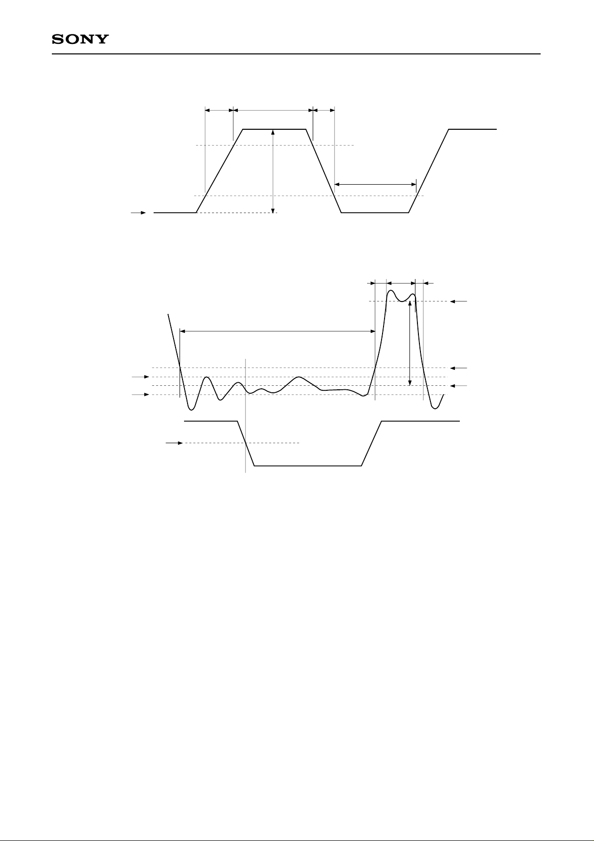
(3) Horizontal transfer clock waveform
tr twh tf
90%
ICX059AK
10%
VHL
(4) Reset gate clock waveform
RG waveform
RGLH
V
RGLL
V
LHφ1 waveform
2.5V
Point A
twl
Vφ
H
twl
twhtr tf
VφRG
VRGH
VRGL + 0.5V
RGL
V
VRGLH is the maximum value and VRGLL is the minimum value of the coupling waveform during the period from
Point A in the above diagram until the rising edge of RG.
In addition, VRGL is the average value of VRGLH and VRGLL.
VRGL = (VRGLH + VRGLL)/2
Assuming VRGH is the minimum value during the interval twh, then:
VφRG = VRGH – VRGL
– 7 –
Page 8
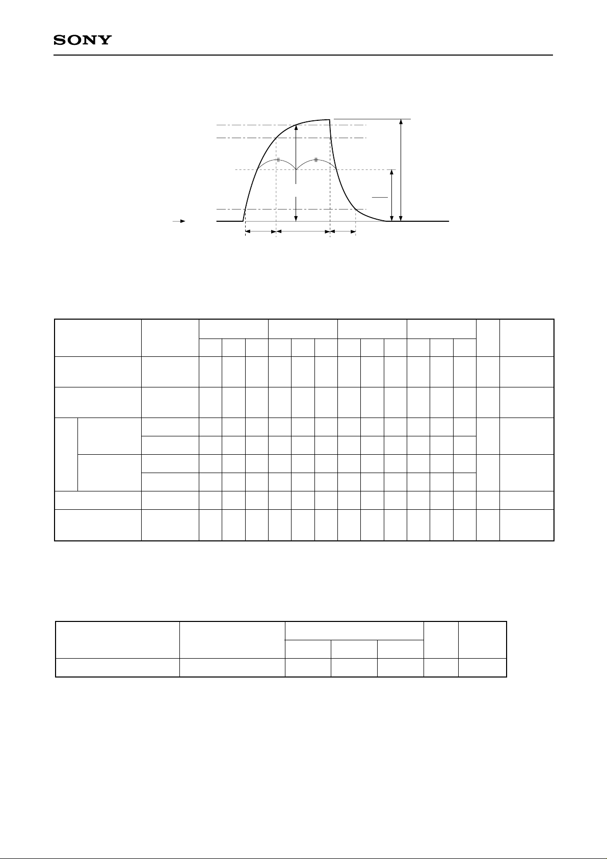
(5) Substrate clock waveform
ICX059AK
100%
90%
φM
VφSUB
10%
SUB
V
0%
tr twh tf
φM
2
Clock Switching Characteristics
Note) Because the horizontal final stage transfer clock LHφ1 is connected to the horizontal transfer clock Hφ1,
specifications will be the same as Hφ1.
Item
Readout clock
Vertical transfer
clock
During
imaging
During
parallel-serial
Horizontal
transfer clock
conversion
Symbol
VT
Vφ1, Vφ2,
Vφ3, Vφ4
H
φ1, LHφ1
H
φ
2
H
φ1, LHφ1
H
φ
2
Min.
2.3
18
21
twh
Typ.
2.5
24
26
6.41
Max.
twl tr tf
Min.
Typ.
Max.
Min.
Typ.
0.5
19.51926
24
10
10
0.01
6.41
0.01
Max.
17.5
15
Min. Typ.
0.5
15
10
10
0.01
0.01
Unit Remarks
Max.
µs
250
ns
17.5
ns
15
µs
During
readout
∗1
∗2
Reset gate clock
Substrate clock
∗1
When vertical transfer clock driver CXD1250 is used.
∗2
tf ≥ tr – 2ns, and the cross-point voltage (VCR) for the Hφ1 · LHφ1 rising side of the Hφ1 · LHφ1 and Hφ2
φ
φ
RG
SUB
11
1.5
13
1.8
51
3
0.5
3
0.5
ns
During
µs
drain charge
waveforms must be at least 2.5V.
two
Item
Symbol
Unit Remarks
Min. Typ. Max.
Horizontal transfer clock
∗3
The overlap period for twh and twl of horizontal transfer clocks Hφ1 · LHφ1 and Hφ2 is two.
Hφ1 · LHφ1, Hφ2
16 20 ns
∗3
– 8 –
Page 9
ICX059AK
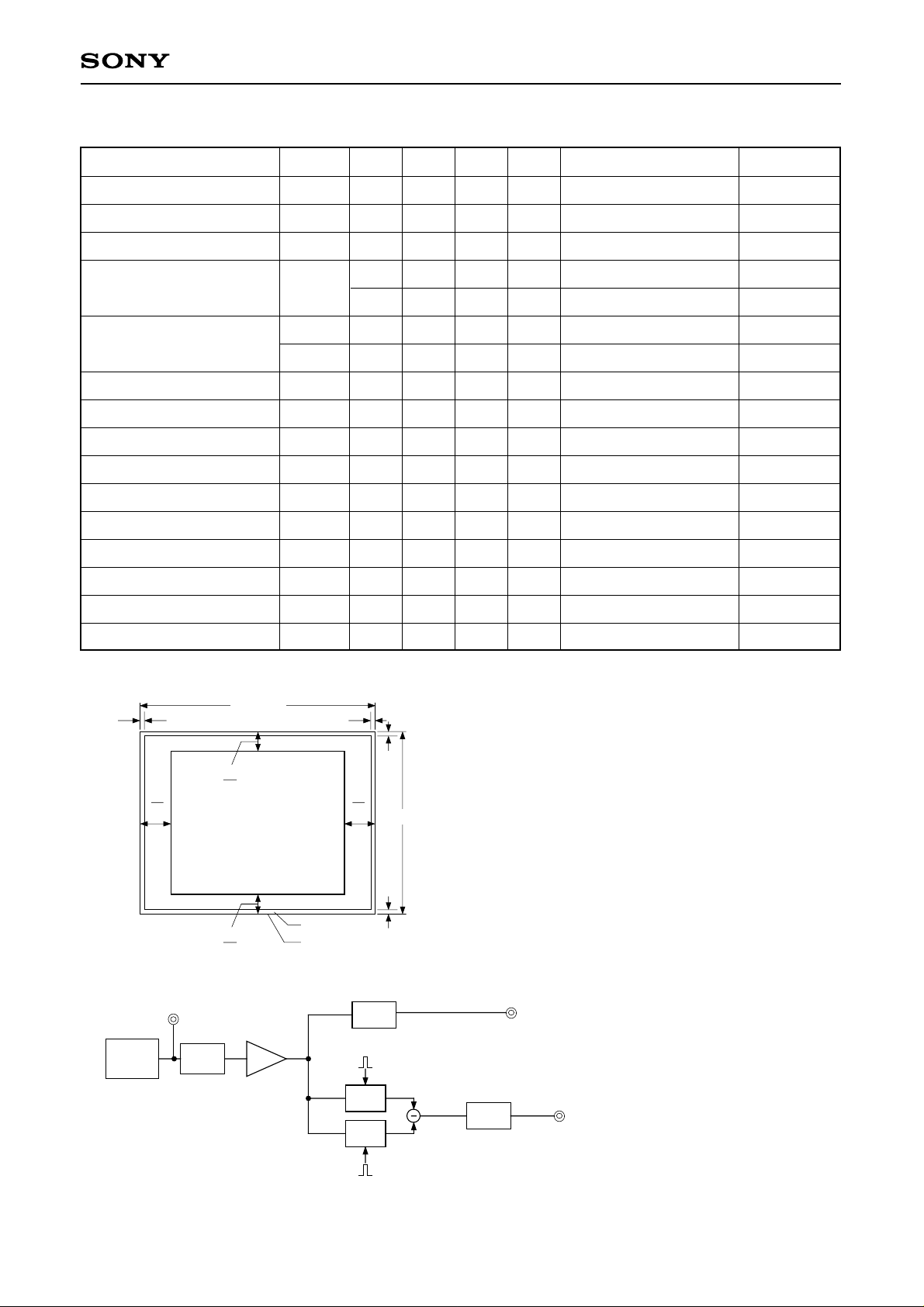
Image Sensor Characteristics (Ta = 25°C)
Item
Sensitivity
Saturation signal
Smear
Video signal shading
Uniformity between video
signal channels
Dark signal
Dark signal shading
Flicker Y
Flicker R-Y
Flicker B-Y
Line crawl R
Line crawl G
Line crawl B
Line crawl W
Symbol Min. Typ. Max. Unit Measurement method Remarks
S
Ysat
Sm
260
540
330
0.009 0.015
20
mV
mV
%
%
1
2
Ta = 60°C
3
4
Zone 0, I
SHy
%
%
%
mV
mV
%
%
%
%
%
%
%
4
Zone 0 to II'
5
5
6
7
Ta = 60°C
Ta = 60°C
8
8
8
9
9
9
9
∆Sr
∆Sb
Ydt
∆Ydt
Fy
Fcr
Fcb
Lcr
Lcg
Lcb
Lcw
25
10
10
2
1
2
5
5
3
3
3
3
Lag
Lag
Zone Definition of Video Signal Shading
752 (H)
12
V
H
8
10
Zone 0, I
V
10
12
H
8
Zone II, II'
Ignored region
Effective pixel region
Measurement System
[∗A]
CCD signal output
CCD C.D.S
AMP
LPF1
(3dB down 6.3MHz)
8
582 (V)
6
0.5
%
[∗Y]
Y signal output
10
S/H
S/H
LPF2
(3dB down 1MHz)
[∗C]
Chroma signal output
Note) Adjust the amplifier gain so that the gain between [∗A] and [∗Y] and between [∗A] and [∗C] equal 1.
– 9 –
Page 10
ICX059AK
Image Sensor Characteristics Measurement Method
Measurement conditions
1) In the following measurements, the substrate voltage and the reset gate clock voltage are set to the values
indicated on the device, and the device drive conditions are at the typical values of the bias and clock
voltage conditions.
2) In the following measurements, spot blemishes are excluded and, unless otherwise specified, the optical
black level (OB) is used as the reference for the signal output, which is taken as the value of Y signal output
or chroma signal output of the measurement system.
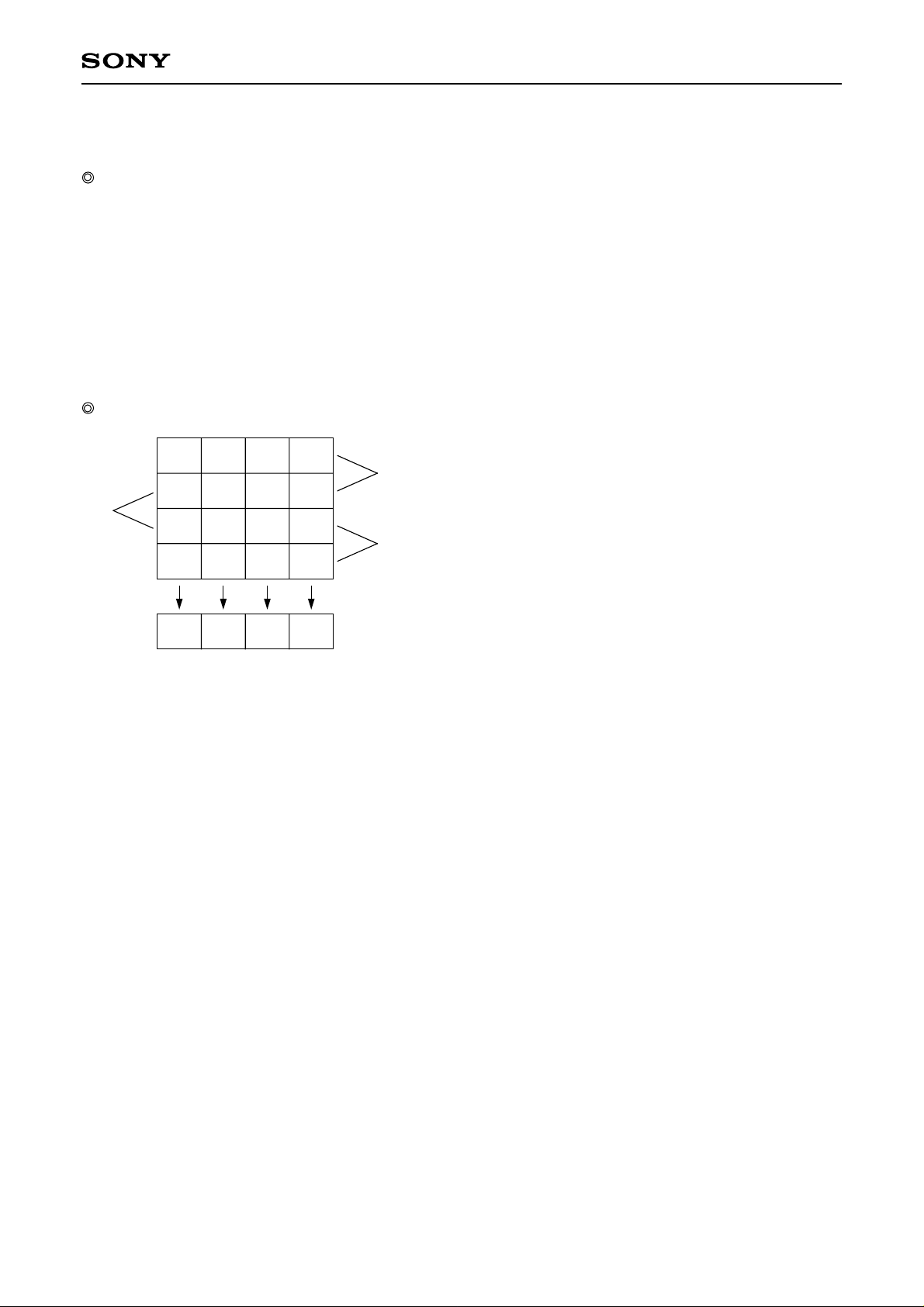
Color coding of this image sensor & Composition of luminance (Y) and chroma (color difference) signals
Cy Ye
G
B
Cy Ye
Mg
Mg
G
Cy Ye
Mg
G
Cy Ye
Mg
As shown in the left figure, fields are read out. The charge is
A1
mixed by pairs such as A1 and A2 in the A field. (pairs such
as B in the B field)
As a result, the sequence of charges output as signals from
A2
G
Hreg
the horizontal shift register (Hreg) is, for line A1, (G + Cy),
(Mg + Ye), (G + Cy), and (Mg + Ye).
Color Coding Diagram
These signals are processed to form the Y signal and chroma (color difference) signal. The Y signal is formed
by adding adjacent signals, and the chroma signal is formed by subtracting adjacent signals. In other words,
the approximation:
Y = {(G + Cy) + (Mg + Ye)} × 1/2
= 1/2 {2B + 3G + 2R}
is used for the Y signal, and the approximation:
R – Y = {(Mg + Ye) – (G + Cy)}
= {2R – G}
is used for the chroma (color difference) signal. For line A2, the signals output from Hreg in sequence are
(Mg + Cy), (G + Ye), (Mg + Cy), (G + Ye).
The Y signal is formed from these signals as follows:
Y = {(G + Ye) + (Mg + Cy)} × 1/2
= 1/2 {2B + 3G + 2R}
This is balanced since it is formed in the same way as for line A1.
In a like manner, the chroma (color difference) signal is approximated as follows:
– (B – Y) = {(G + Ye) – (Mg + Cy)}
= – {2B – G}
In other words, the chroma signal can be retrieved according to the sequence of lines from R – Y and – (B – Y)
in alternation. This is also true for the B field.
– 10 –
Page 11

ICX059AK
Definition of standard imaging conditions
1) Standard imaging condition I:
Use a pattern box (luminance 706cd/m2, color temperature of 3200K halogen source) as a subject. (Pattern
for evaluation is not applicable.) Use a testing standard lens with CM500S (t = 1.0mm) as an IR cut filter and
image at F5.6. The luminous intensity to the sensor receiving surface at this point is defined as the standard
sensitivity testing luminous intensity.
2) Standard imaging condition II:
Image a light source (color temperature of 3200K) with a uniformity of brightness within 2% at all angles.
Use a testing standard lens with CM500S (t = 1.0mm) as an IR cut filter. The luminous intensity is adjusted
to the value indicated in each testing item by the lens diaphragm.
1. Sensitivity
Set to standard imaging condition I. After selecting the electronic shutter mode with a shutter speed of
1/250s, measure the Y signal (Ys) at the center of the screen and substitute the value into the following
formula.
S = Ys × [mV]
250
50
2. Saturation signal
Set to standard imaging condition II. After adjusting the luminous intensity to 10 times the intensity with
average value of the Y signal output, 200mV, measure the minimum value of the Y signal.
3. Smear
Set to standard imaging condition II. With the lens diaphragm at F5.6 to F8, adjust the luminous intensity to
500 times the intensity with average value of the Y signal output, 200mV. When the readout clock is
stopped and the charge drain is executed by the electronic shutter at the respective H blankings, measure
the maximum value YSm [mV] of the Y signal output and substitute the value into the following formula.
Sm =
YSm
××
200
1
500
1
× 100 [%] (1/10V method conversion value)
10
4. Video signal shading
Set to standard imaging condition II. With the lens diaphragm at F5.6 to F8, adjust the luminous intensity so
that the average value of the Y signal output is 200mV. Then measure the maximum (Ymax [mV]) and
minimum (Ymin [mV]) values of the Y signal and substitute the values into the following formula.
SHy = (Ymax – Ymin)/200 × 100 [%]
5. Uniformity between video signal channels
Set to standard imaging condition II. Adjust the luminous intensity so that the average value of the Y signal
output is 200mV, and then measure the maximum (Crmax, Cbmax [mV]) and minimum (Crmin, Cbmin
[mV]) values of the R – Y and B – Y channels of the chroma signal and substitute the values into the
following formula.
∆Sr = | (Crmax – Crmin)/200 | × 100 [%]
∆Sb = | (Cbmax – Cbmin)/200 | × 100 [%]
6. Dark signal
Measure the average value of the Y signal output (Ydt [mV]) with the device ambient temperature 60°C and
the device in the light-obstructed state, using the horizontal idle transfer level as a reference.
– 11 –
Page 12

ICX059AK
7. Dark signal shading
After measuring 6, measure the maximum (Ydmax [mV]) and minimum (Ydmin [mV]) values of the Y signal
output and substitute the values into the following formula.
∆Ydt = Ydmax – Ydmin [mV]
8. Flicker
1) Fy
Set to standard imaging condition II. Adjust the luminous intensity so that the average value of the Y signal
output is 200mV, and then measure the difference in the signal level between fields (∆Yf [mV]). Then
substitute the value into the following formula.
Fy = (∆Yf/200) × 100 [%]
2) Fcr, Fcb
Set to standard imaging condition II. Adjust the luminous intensity so that the average value of the Y signal
output is 200mV, insert an R or B filter, and then measure both the difference in the signal level between
fields of the chroma signal (∆Cr, ∆Cb) as well as the average value of the chroma signal output (CAr, CAb).
Substitute the values into the following formula.
Fci = (∆Ci/CAi) × 100 [%] (i = r, b)
9. Line crawls
Set to standard imaging condition II. Adjust the luminous intensity so that the average value of the Y signal
output is 200mV, and then insert a white subject and R, G, and B filters and measure the difference
between Y signal lines for the same field (∆Ylw, ∆Ylr, ∆Ylg, ∆Ylb [mV]). Substitute the values into the
following formula.
Lci = (∆Yli/200) × 100 [%] (i = w, r, g, b)
10. Lag
Adjust the Y signal output value generated by strobe light to 200mV. After setting the strobe light so that it
strobes with the following timing, measure the residual signal (Ylag). Substitute the value into the following
formula.
Lag = (Ylag/200) × 100 [%]
FLD
SG1
Strobe light
timing
Output
Light
Ylag (lag)Y signal output 200mV
– 12 –
Page 13

–8.5V
A]
∗
[
ICX059AK
CCD OUT
1M
1/35V
3.3/16V
820
100k39k
47/6.3V
1/6.3V
100
7
12345 6 8
3.9k
0.01
2SK523
V
V
OUT
V
SS
V
GG
GND
Vφ
1
Vφ
2
Vφ
3
Vφ
4
DD
GND
SUB
V
L
RG
ICX059
(BOTTOM VIEW)
13 12 11 10 9
LHφ
1
Hφ
1
Hφ
2
3.3/20V
16 15 14
0.01
15k
47k
15k
39k
0.1
2SC2785 × 3
270k
0.1
27k
0.1
56k
100k
1/35V
1/35V
10/20V
22/16V
22/20V
Drive Circuit
15V
201918171615141312
CXD1250
1
2
3
4
5
6
7
8
5V
XV2
XSUB
XV1
XSG1
XV3
XSG2
9
XV4
11
10
22
/10V
– 13 –
Hφ2Hφ1
100k
1/20V
50k
RG
Page 14
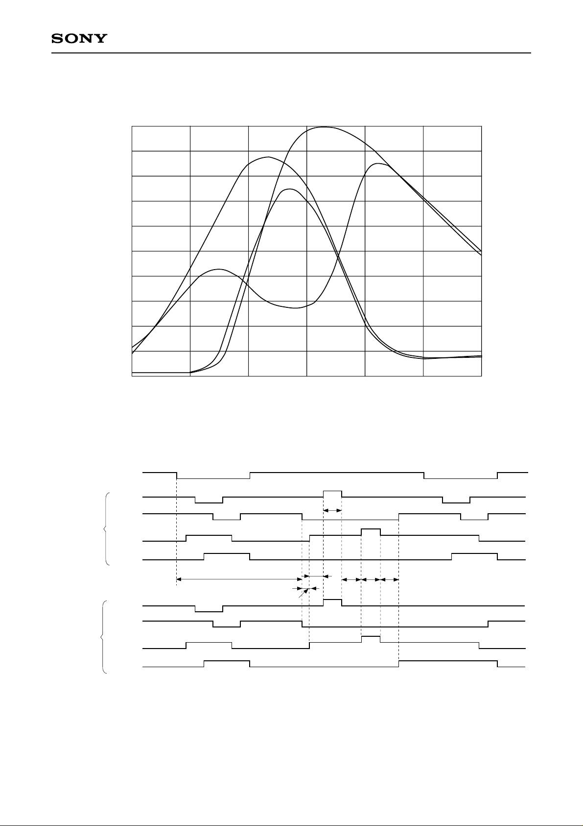
Spectral Sensitivity Characteristics
(Includes lens characteristics, excludes light source characteristics)
ICX059AK
1.0
0.9
0.8
0.7
0.6
0.5
0.4
Relative Response
0.3
0.2
0.1
0.0
400
450
Cy
500
Wave Length [nm]
Mg
Ye
G
600
650
700550
Sensor Readout Clock Timing Chart
HD
V1
V2
Odd Field
V3
V4
V1
V2
Even Field
V3
V4
41.6
0.2
1.6
2.5
2.5 2.5 2.5
Unit : µs
– 14 –
Page 15
340
ICX059AK
25
335
330
325
320
315
310
5
3
1
5
3
1
582
6
4
2
6
4
2
581
FLD
VD
BLK
HD
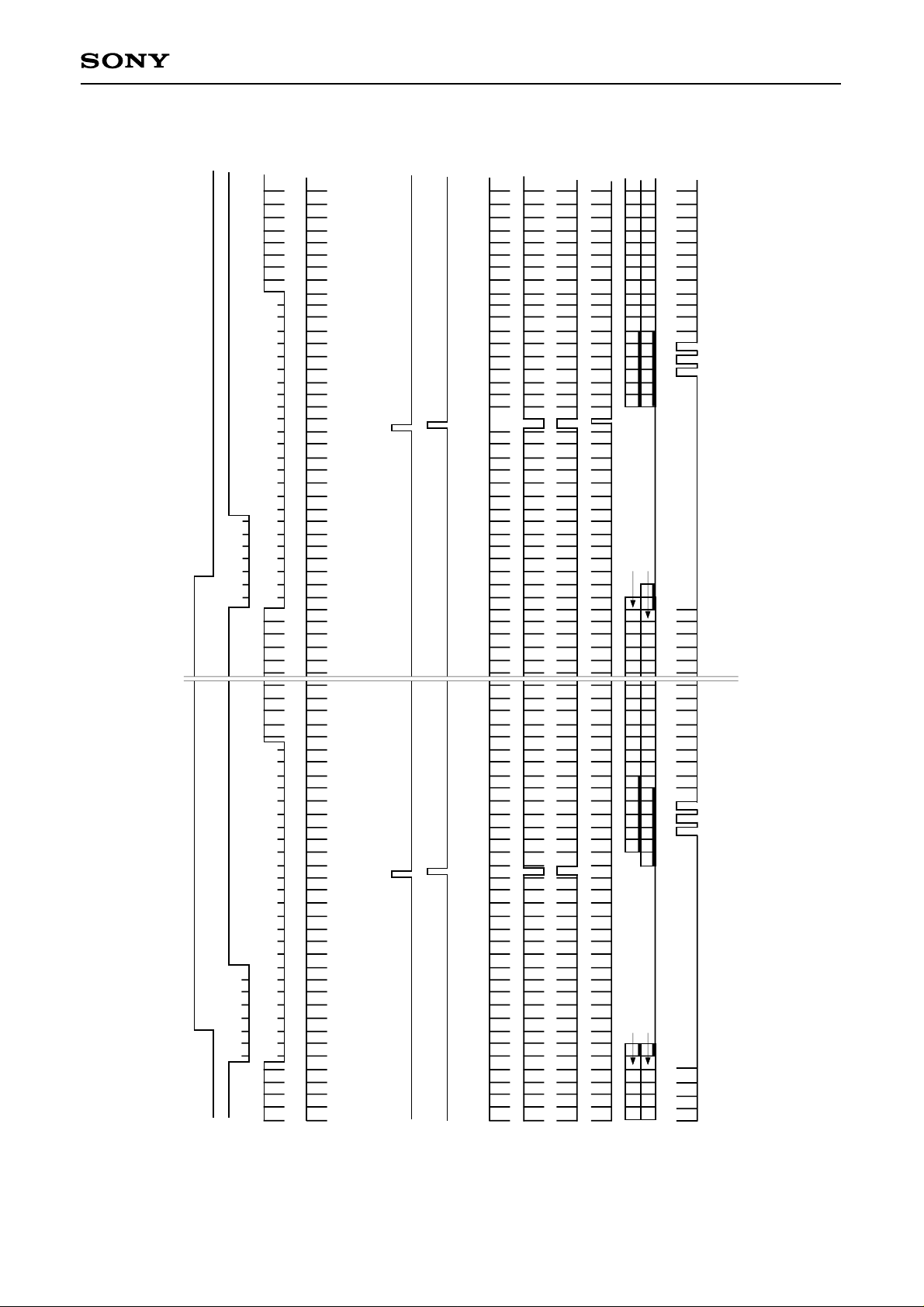
Drive Timing Chart (Vertical Sync)
V4
246
246
581
CCD
135
135
582
OUT
CLP1
20
15
10
5
4
3
2
1
625
620
V1
V2
SG1
SG2
V3
– 15 –
Page 16
ICX059AK
20
10
3
2
1
3
2
1
22
20
10
5
3
2
1
HD
BLK
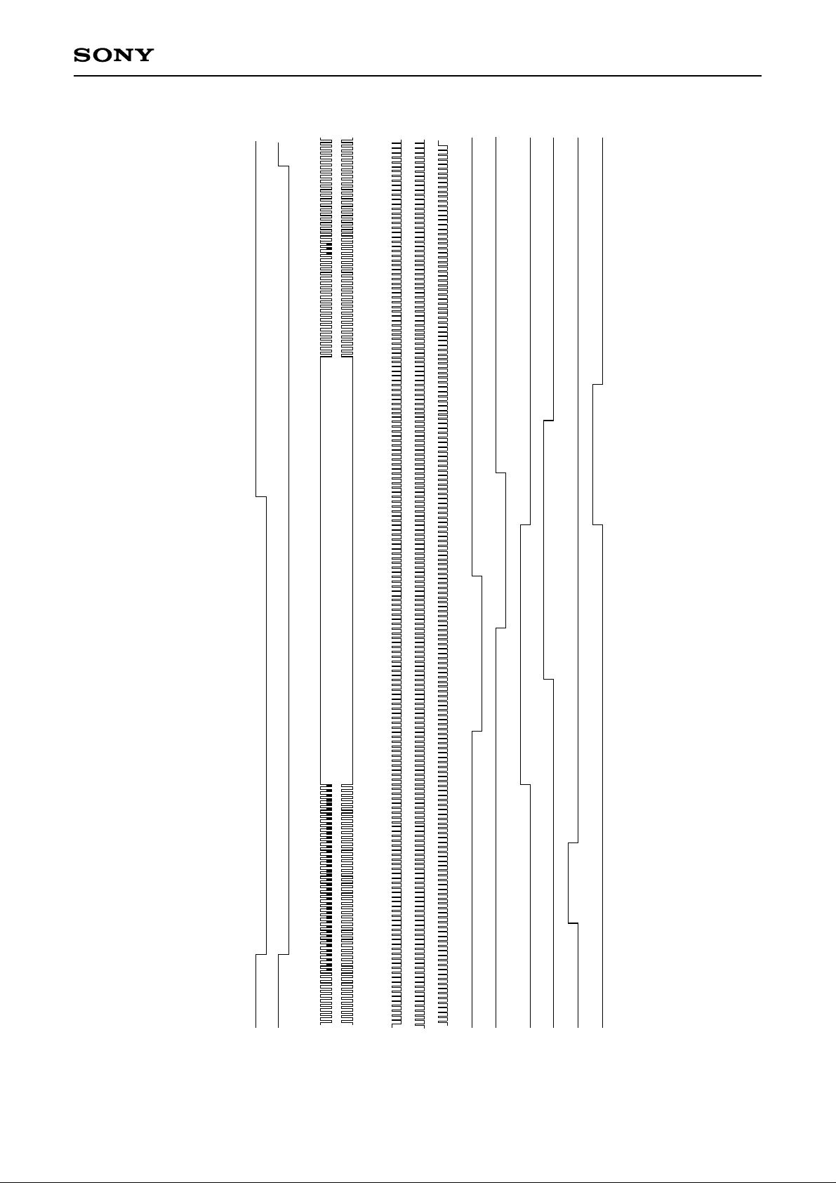
Drive Timing Chart (Horizontal Sync)
H2
H1/LH1
40
30
20
10
5
3
1
752
750
745
V1
V2
V3
RG
SHP
SHD
V4
CLP1
SUB
– 16 –
Page 17

ICX059AK
Notes on Handling
1) Static charge prevention
CCD image sensors are easily damaged by static discharge. Before handling be sure to take the following
protective measures.
a) Either handle bare handed or use non-chargeable gloves, clothes or material.
Also use conductive shoes.
b) When handling directly use an earth band.
c) Install a conductive mat on the floor or working table to prevent the generation of static electricity.
d) Ionized air is recommended for discharge when handling CCD image sensor.
e) For the shipment of mounted substrates, use boxes treated for the prevention of static charges.
2) Soldering
a) Make sure the package temperature does not exceed 80°C.
b) Solder dipping in a mounting furnace causes damage to the glass and other defects. Use a ground 30W
soldering iron and solder each pin in less than 2 seconds. For repairs and remount, cool sufficiently.
c) To dismount an image sensor, do not use a solder suction equipment. When using an electric desoldering
tool, use a thermal controller of the zero cross On/Off type and connect it to ground.
3) Dust and dirt protection
a) Operate in clean environments (around class 1000 is appropriate).
b) Do not either touch glass plates by hand or have any object come in contact with glass surfaces. Should
dirt stick to a glass surface, blow it off with an air blower. (For dirt stuck through static electricity ionized air
is recommended.)
c) Clean with a cotton bud and ethyl alcohol if the grease stained. Be careful not to scratch the glass.
d) Keep in a case to protect from dust and dirt. To prevent dew condensation, preheat or precool when
moving to a room with great temperature differences.
e) When a protective tape is applied before shipping, just before use remove the tape applied for
electrostatic protection. Do not reuse the tape.
4) Do not expose to strong light (sun rays) for long periods, color filters will be discolored.
5) Exposure to high temperature or humidity will affect the characteristics. Accordingly avoid storage or usage
in such conditions.
6) CCD image sensors are precise optical equipment that should not be subject to mechanical shocks.
– 17 –
Page 18
2.5
ICX059AK
2-R0.5
16
9
0° to 9°
C
D
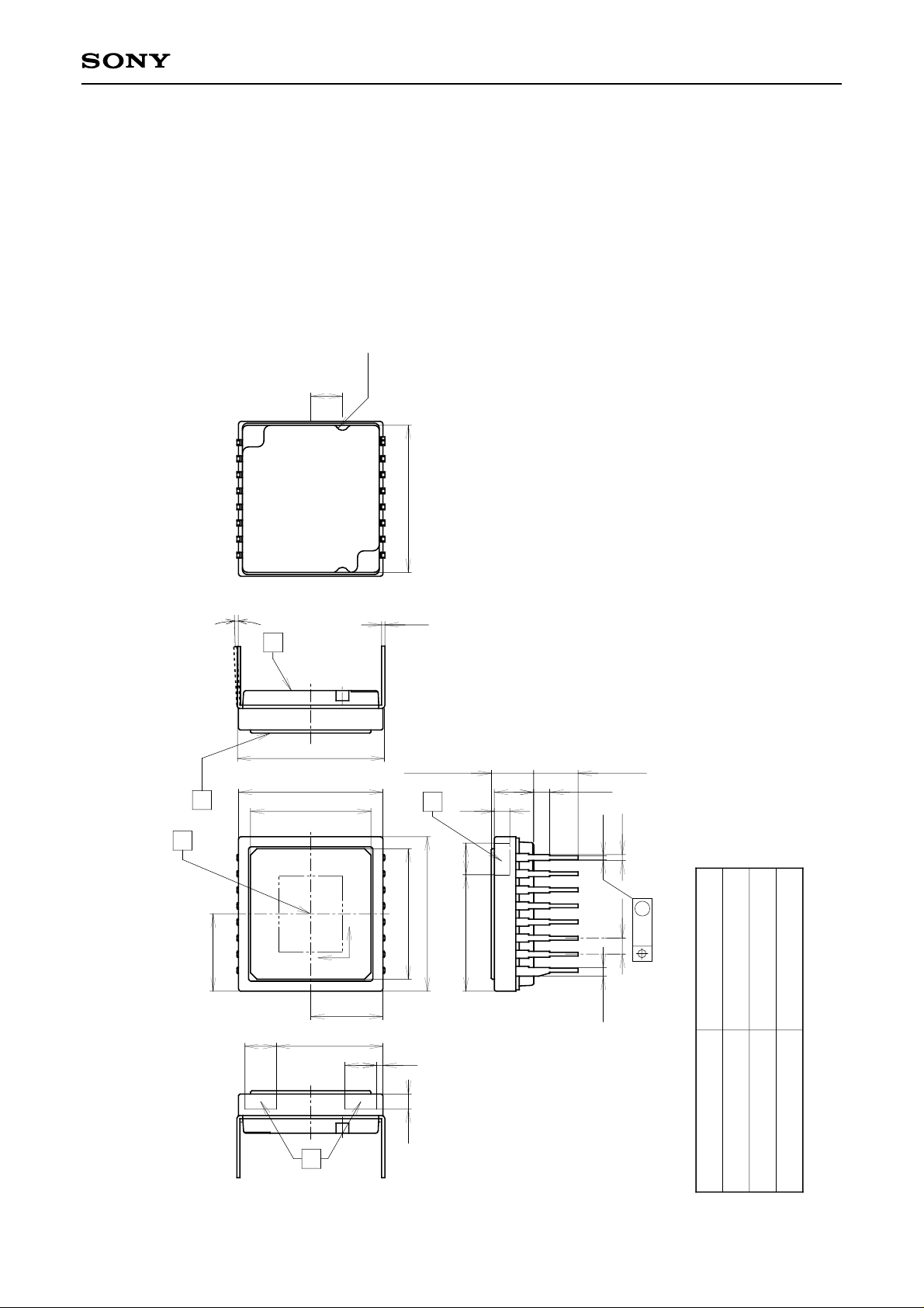
16pin DIP (450mil)
A
11.43
9.5
1
11.6
8
0.25
1. “A” is the center of the effective image area.
2. The two points “B” of the package are the horizontal reference.
The point “B'” of the package is the vertical reference.
3. The bottom “C” of the package, and the top of the cover glass “D”
are the height reference.
4. The center of the effective image area relative to “B” and “B'”
is (H, V) = (6.1, 5.7) ± 0.15mm.
5. The rotation angle of the effective image area relative to H and V is ± 1°.
6. The height from the bottom “C” to the effective image area is 1.41 ± 0.10mm.
The height from the top of the cover glass “D” to the effective image area is 1.94 ± 0.15mm.
7. The tilt of the effective image area relative to the bottom “C” is less than 50µm.
The tilt of the effective image area relative to the top “D” of the cover glass is less than 50µm.
8. The thickness of the cover glass is 0.75mm, and the refractive index is 1.5.
9. The notches on the bottom of the package are used only for directional index, they must
not be used for reference of fixing.
3.35 ± 0.15
11.4 ± 0.1
B'
2.5
3.1
1.2
0.3
~
3.5 ± 0.3
1.27
0.46
Package Outline Unit: mm
6.1
2.5
~
M
0.69
1.27
0.3
Plastic
GOLD PLATING
42 ALLOY
0.9g
8.4
10.3
H
V
5.7
2.5
12.2 ± 0.1
0.5
9.2
~
(For the first pin only)
1.2
B
PACKAGE MATERIAL
LEAD TREATMENT
PACKAGE WEIGHT
LEAD MATERIAL
PACKAGE STRUCTURE
– 18 –
 Loading...