

Page 1
Bay Linear, Inc
2478 Armstrong Street, Livermore, CA 94550 Tel: (925) 989-7144, Fax: (925) 940-9556 www.baylinear.com
3-1/2 Digit LCD/LED Display, A/D Converter
ICL7106 / 7107
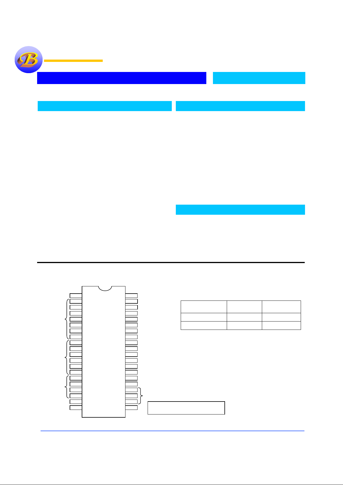
Pin Connection
Ordering Information
Device Package Temp.
ICL7106P 40PDIP
0 to 70°C
ICL7107P 40PDIP
0 to 70°C
Description
The ICL7106 and ICL 7107 are high performance, low power
3-1/2 digit A/D converters. Included are seven segment
decoders, Display drivers, a reference and a clock. The ICL
7106 is designed to interface with a liquid crystal display
(LCD and includes a multiplexed backplane drive; the ICL
7107 will directly drive an instrument size light emitting diode
(LED) display.
The ICL7106 and ICL 7107 bring together a combination of
high accuracy, versatility and true economy. True differential
inputs and reference are useful in all systems, but give the
designer advantage when measurin g load cells, strain gauges,
and other Bridge type transducers.
By providing the true economy of a single power supply
operation, the ICL7106 enables a high performance panel
meter to be built with the addition of only 10 passive
components and a display.
Features
• Guaranteed Zero Reading for OV Input
on All Scales
• True Polarity at Zero for Precise Null
Detection
• True Differential Input and Reference,
Direct Display Drive
• Low Noise less than 15µµµµVp-p
• On chip clock and reference
• Low Power Dissipation, ≤≤≤≤10mW (typ.)
• No Additional Active Circuits Required
• Available in Small Outline Surface Mount
Package, 44MQFP
Applications
• 7106 for LCD
• 7107 for LED
• Measuring Bridge Type Transducers
• Instrumentation
• Digital Thermometers
1 V+
2 D1
3 C1
4 B1
5 A1
6 F1
7 G1
8 E1
9 D2
10 C2
11 B2
12 A2
13 F2
14 E2
15 D3
16 B3
17 F3
18 E3
19 AB4
20 POL
OSC1 40
BP 21
G3 22
A3 23
C3 24
G2 25
V- 26
IN HI 31
IN LO 30
A-Z 29
BUFF 28
INT 27
TEST 37
REF HI 36
REF LO 35
C
REF
+
34
C
REF
-
33
COM 32
OSC2 39
OSC3 38
(
100’s
)
(
100’s
)
(
10’s
)
(
1’s
)
(
1000
)
(
Minus
)
Bay Linear
Bay LinearBay Linear
Bay Linear
ICL7106P
For 7107, Pin 21 is GND
’
Bay Linear
Bay LinearBay Linear
Bay Linear
Inspire the Linear Power
Ins
p
ire the Linear PowerInspire the Linear Power
Ins
p
ire the Linear Power
Page 2
Bay Linear, Inc
2478 Armstrong Street, Livermore, CA 94550 Tel: (925) 989-7144, Fax: (925) 940-9556 www.baylinear.com
ICL7106 / 7107
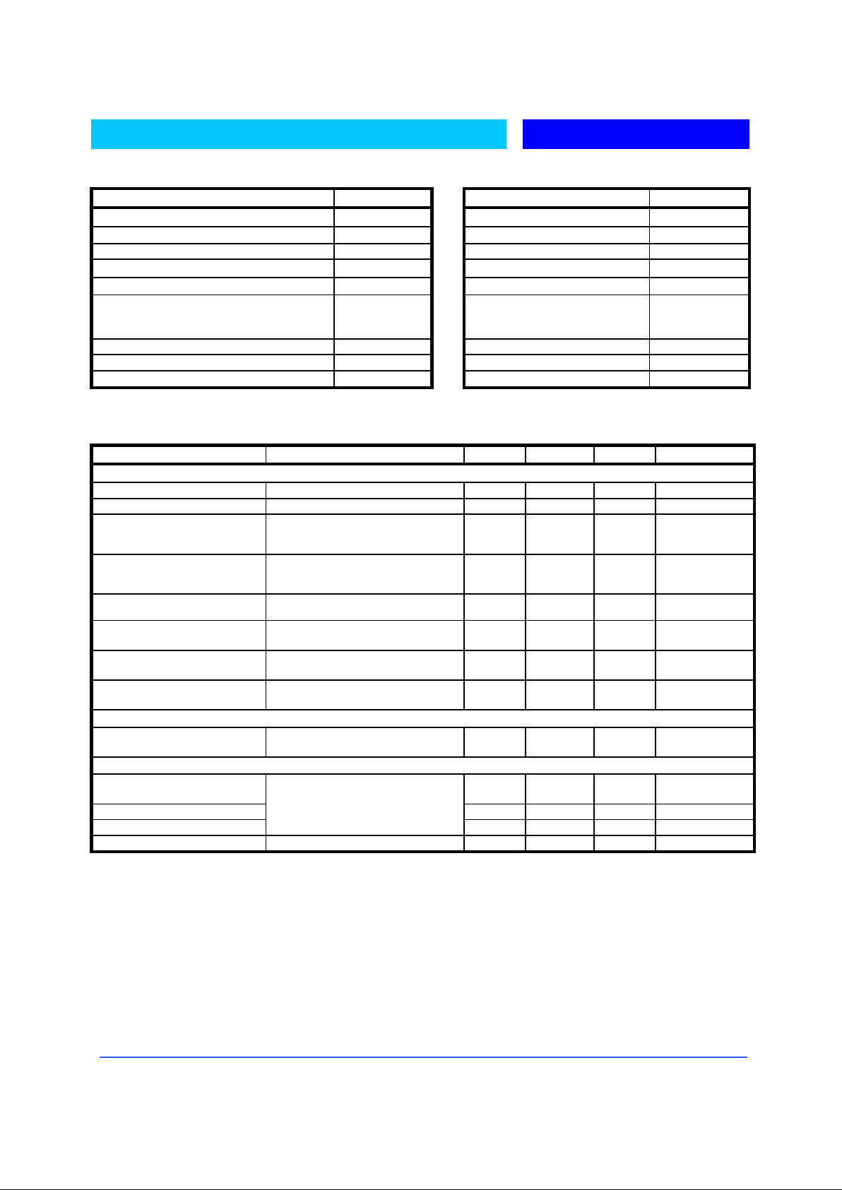
Absolute Maximum Rating Thermal Information
Parameter Parameter
Input Supply Voltage Thermal Resistance, Typical
θ
JA
(°C/W)
ICL7106 , V+ to V-
15V PDIP 50
ICL7107, V+ to GND 6V MQFP 75
ICL7107, V- to GND
-
9V
Max. Junction Temperature
150°C
Analog Input Voltage (Either Input) (Note 1)
V+ to V
-
Max. Storage Temperature Range
-65°C to 150°C
Reference Input Voltage (Either Input)
V+ to V
-
Max. Lead Temperature
(Soldering 10S)
MQFP – Lead Tips Only
300°C
Clock Input
ICL7106 TEST to V+ Operating Temperature Range
0°C to 70°C
ICL7107 GND to V+
Electrical Characteristics
(TA = 25°C , F
CLOCK
= 48kHz unless otherwise specified, see Note 2)
Parameter Conditions MIN TYP MAX UNIT
System Performance
Zero Input Reading
VIN = 0.0V, Full Scale = 200mV
-000.0
±
000.0
±
000.0
Digital Reading
Ratiometric Reading
V
IN
= V
REF
, V
REF
= 100mV
999/1000
Rollover Error
-V
IN
= +VIN ≅ 200Mv
Difference In Rea ding for Eq ual Positive
and Negative Inputs Near Full Scale
-1 +1 Counts
Linearity
Full Scale = 200mV or Full Scale = 2V
Maximum Deviation from Best straight
Line fit (Note 3)
-1 +1 Counts
Common Mode Rejection Ratio
V
CM
= 1V, VIN = 0V, Full Scale =
200mV (Note 3)
50
µ
V/V
End Power Supply Character
V+ Supply Current
V
IN
= 0 (Does Not Include LED Current
for ICL7107)
1.8 mA
End Power Supply Character
V- Supply Current
ICL7107 Only
1.8 MA
Common Pin Analog Common
Voltage
25 kΩ Between Common and Positive
Supply ( With Respect to + Supply
2.4 3.2 V
Display Driver ICL7106 Only
Pk-Pk Segment Drive Voltage
Pk-Pk Backplane Drive Voltage
V+ = to V- = 9V
4 5 6 V
Display Driver ICL7107 Only
Segment Sinking Current
(Except Pin 19 and 20)
V+ = 5V, Segment Voltage = 3V
5
8
mA
Pin 19 Only 10 16 mA
Pin 20 Only 4 7 mA
Notes:
1. Input voltages may exceed the supply voltages provided the input current is limited to ±100µA.
2. Unless otherwise noted, specifications apply to both the ICL7106 and ICL7107 at T
A
= +25°C, f
CLOCK
= 48kHz. ICL7107 is tested in the circuit
of Figure 1. ICL7107 is tested in the circuit of Figure 2.
3. Not Tested, guaranteed by design
Page 3

Bay Linear, Inc
2478 Armstrong Street, Livermore, CA 94550 Tel: (925) 989-7144, Fax: (925) 940-9556 www.baylinear.com
ICL7106/7107
Typical Applications and Test Circuits
Figure 1. ICL7106 test circuit and typical application with LCD display components selected for 200mV full scale.
Figure 2. ICL7107 test circuit and typical application with LED display components selected for 200mV full scale.
Page 4

Bay Linear, Inc
2478 Armstrong Street, Livermore, CA 94550 Tel: (925) 989-7144, Fax: (925) 940-9556 www.baylinear.com
Design Information Summary Sheet
!" Oscillator Frequency Summary Sheet
f
OSC
= 0.45/RC
C
OSC
>
50pF; R
OSC
>
50kΩ
f
OSC
(typ) = 48kHz
!" Oscillator Period
t
OSC
= RC/0.45
!" Integration Clock Frequency
F
CLOCK
= f
OSC
/4
!" Integration Period
t
INT
=1000 x (4/f
OSC
)
!" 60/50Hz Rejection Criterion
t
INT /t60HZ
or t
INT /t60HZ
= Integer
!" Optimum Integration Current
I
INT
= 4µA
!" Full Scale Analog Inout Voltage
V
INFS
(Typ) = 200mV or 2V
!" Integration Resistor
R
INT
=
V
INFS
I
INT
!" Integration Capacitor
C
INT
=
(t
INT
)(I
INT
)
V
INT
!" Integrator Output Voltage Swing
V
INT =
(t
INT
)(I
INT
)
C
INT
!" V
INT
Maximum Swing
(V- + 0.5V) < V
INT <
(V+ = -0.5V), V
INT
(typ) = 2V
!" Display Count
Count = 1000 x
V
IN
V
REF
!"
Conversion Cycle
t
CYC = tCLOCK
x 4000
t
CYC = tOSC
x 16,000
when f
OSC
= 48kHz; t
CYC
= 333ms
!" Common Mode Input Voltage
(V- + 1V) < V
IN <
(V+ = -0.5V)
!" Auto-Zero Capacitor
0.01µF < C
AZ <
1µF
!" Reference Capacitor
0.01µF < C
REF <
1µF
!" V
COM
Biased between Vi and V-
!" V
COM
≅≅≅≅ V+ - 2.8V
Regulation lost when V+ to V- < ≅6.8V
If V
COM
is externally pulled down to (V+ to V-) / 2,
the V
COM
circuit will turn off.
!" ICL7106 Power Supply: Single 9V
V+ - V- = 9V
Digital supply is generated internally
V
GND
≅
V+ - 4.5V
!" ICL7106 Display: LCD
Direct drive type with digital logic supply amplitude.
!" ICL7107 Power Supply: Dual ±
±±
±5.0V
V+ = +5V to GND
V- = -5V to GND
Digital Logic and LED driver supply V+ to GND
!" ICL7106 Display: LED
Non-Multiplexed Common Anode
Advance Information
-
These data sheets contain descriptions of products that are in development. The specifications are based on the engineering calculations,
computer simulations and/ or initial prototype evaluation.
Preliminary Information
-
These data sheets contain minimum and maximum specifications that are based on the initial device characterizations. These limits are
subject to change upon the completion of the full characterization over the specified temperature and supply voltage ranges.
The application circuit examples are only to explain the representative applications of the devices and are not intended to guarantee any circuit
design or permit any industrial property right to other rights to execute. Bay Linear takes no responsibility for any problems related to any
industrial property right resulting from the use of the contents shown in the data book. Typical parameters can and do vary in different
applications. Customer’s technical experts must validate all operating parameters including “ Typical” for each customer application.
LIFE SUPPORT AND NUCLEAR POLICY
Bay Linear products are not authorized for and should not be used within life support systems which are intended for surgical
implants into the body to support or sustain life, in aircraft, space equipment, submarine, or nuclear facility applications without
the specific written consent of Bay Linear President.
 Loading...