

Page 1
IA3004-CE10A
Contact image sensor heads
Color image sensor head (300dpi)
IA3004-CE10A
The IA3004-CE10A is a color image sensor head that uses LED chips of the three colors red, green, and blue. Through
the use of ROHM’s further improvements in optical technologies and LSI circuit designing, the IA3004-CE10A provides
excellent color reproducibility and noise resistance and has taken its place as the industry’s highest level compact and
lightweight image sensor head.
Applications
!!!!
Color scanners
Check readers
Image scanning devices
Features
!!!!
1) Each sensor IC is equipped with a built-in amplifier for greatly increased noise resistance.
2) Red, green, and blue LED chips are used for the light source to obtain excellent color reproducibility.
3) Uses a single power supply operational amplifier. Operation requires only a single 5V power supply.
4) Uses a ceramic board as the base board for excellent dimensional stability, and excellent stability in optical
characteristics.
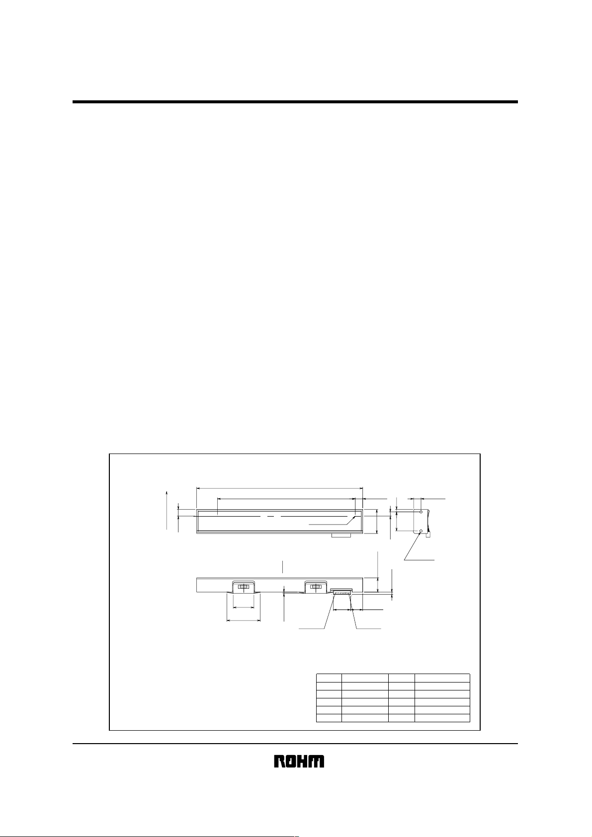
External dimensions
!!!!
Note) Diflection at the top of glass : 0~0.25 Projection to platen is positive.
Socket Housing : IL-Z-9S-S125C3(JAE)
Socket Contact : IL-Z-C3-A-15000(JAE)
(Units : mm)
(5)
Paper feed direction
124±0.5
103(Effective Reading Width : 101.6)
C
L
A
(15.5)
(25)
Max. 1.5
No.9
No.1 Pixel
Pin No.
No.1
No.2
No.3
No.4
No.5
(12.9)
Ao
GND
SI
CLK
DD
V
5.5±0.3
(9.05)
No.1
14.2±0.2
4−φ1.9
Effective Depth 7
5.5±0.2
SignalSignal Pin No.
R-GND
G-GND
B-GND
VLED
1.9±0.2
18±0.5
3.1±0.3
10.68±0.4
Max.2
No.6
No.7
No.8
No.9
Page 2
Contact image sensor heads
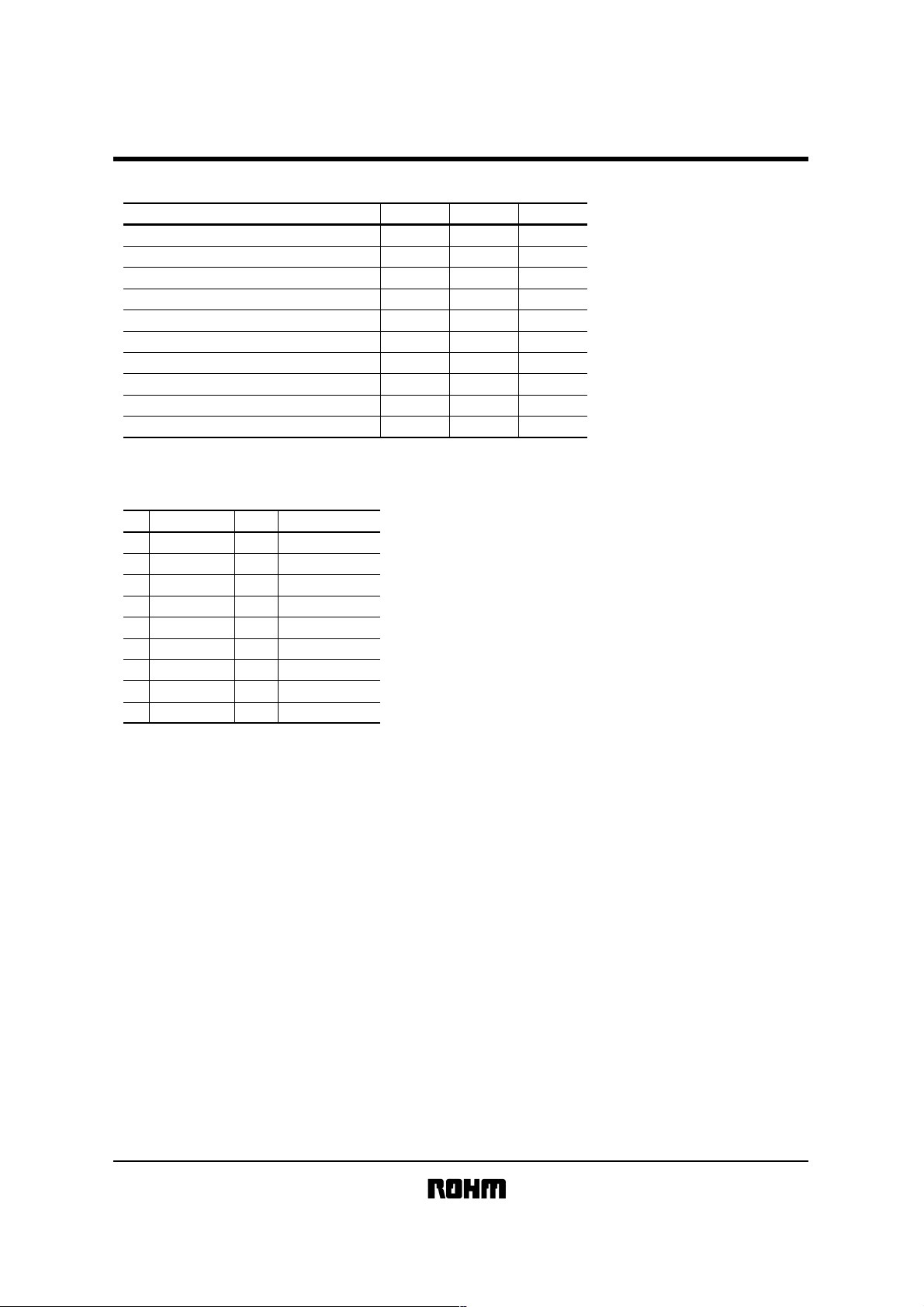
Characteristics
!!!!
Parameter
Effective scanning width
Primary scan dot density
Total dot number
Power supply voltage
Scanning speed
Clock frequency
Maximum dynamic range
Minimum dynamic range
Dark output
Operating temperature
Pin assignments
!!!!
Symbol Typ. Unit
−
−
−
DD
V
SLT
CLK
VRMax.
VRMin.
Vod
−
101.6
300
1216
5
3
3
0.5
0.25
1.0±0.1
5~45
mm
dpi
dots
V
ms / line
MHz
V
V
V
°C
IA3004-CE10A
No.
1
2
3
4
5
6
7
8
9
Circuit
Ao
GND
Sl
CLK
DD
V
R-GND
G-GND
B-GND
VLED
I / O
Analog output
O
Ground
I
I
Serial-in
I
Clock
I
Power supply
I
LED red ground
I
LED green ground
I
LED blue ground
I
LED power supply
Functions
Page 3

Contact image sensor heads
Timing chart
!
(a) CLK Timing Chart
1/fCLK
tw1
tw2
CLK
0 1 11 12 13
IA3004-CE10A
tSETUP
tHOLD
SI
ts
Ao
1 pixel 2 pixel
Fig.1
(b) Data Output Timing Chart
After turning on the SI pulse, the analog output shape starts from the setting down point of 12CLK pulse.
0
2 4 6 8 10 12 14 16
CLK
SI
Ao
Note) The CLK section area which is over the effective pixel numbers
(Output blank part) cannot be used as the analog Output standard level.
Page 4

Contact image sensor heads
Equivalent circuit
!
V
DD
GND
O
A
SI
CLK
LED
V
R
GND
G
GND
B
GND
1µF×4
1
IA3004-CE10A
1216
1216 BIT SHIFT REGISTER
Fig.2
 Loading...