

Page 1
400 Hot Springs Road, Carson City NV 89706 • (775) 883-0820 • Fax (775) 883-0827 • www.hytek.com • 33
HY-7110
Micro-heater
TEC Controllers Laser Diode Drivers Micro-heaters
Miniature Proportionally
Controlled Heater
Description:
The HY71 10
is a miniature proportionally controlled heater
whose temperature can be programmed with a single external resistor. This device is ideally suited for regulating the
temperature of sensitive electronic components such as microwave filters, optical waveguides, multiplexers and crystal
oscillators. The HY71 10 in a ceramic package can supply
up to 28 Watts of power from an unregulated 28 V olt supply .
Operating characteristics:
Characteristic Symbol Min Max Unit
Supply Voltage
VDD +8 +35 Vdc
(Pin 1 to Pin 2)
Steady State Supply
I
S
0.015 1.0 Adc
Current @ VDD = +35 Vdc
Temperature variation over
∆T
V
2°C
operating voltage
Temperature variation
∆T
L
10 °C
with load
Control T emperature Range T
C
50 100 °C
Control Resistor Value
R
C
0 35K Ω
Pin 3 to Pin 4 (See Figure 1)
Maximum Control
T
MAX
110 °C
Temperature when Rc = 0Ω
Turn on power at start-up
P
D
25 28 Watts
@VDD = +28 Volts
Maximum ratings:
Rating Symbol Value Unit
Supply Voltage VDD 35 Vdc
Reverse Voltage VR –50 Vdc
Power Dissipation PD 35 Watts
Operating Temperature (Case) TMAX/MIN 100/–20 °C
Storage Temperature Range –65 to +150 °C
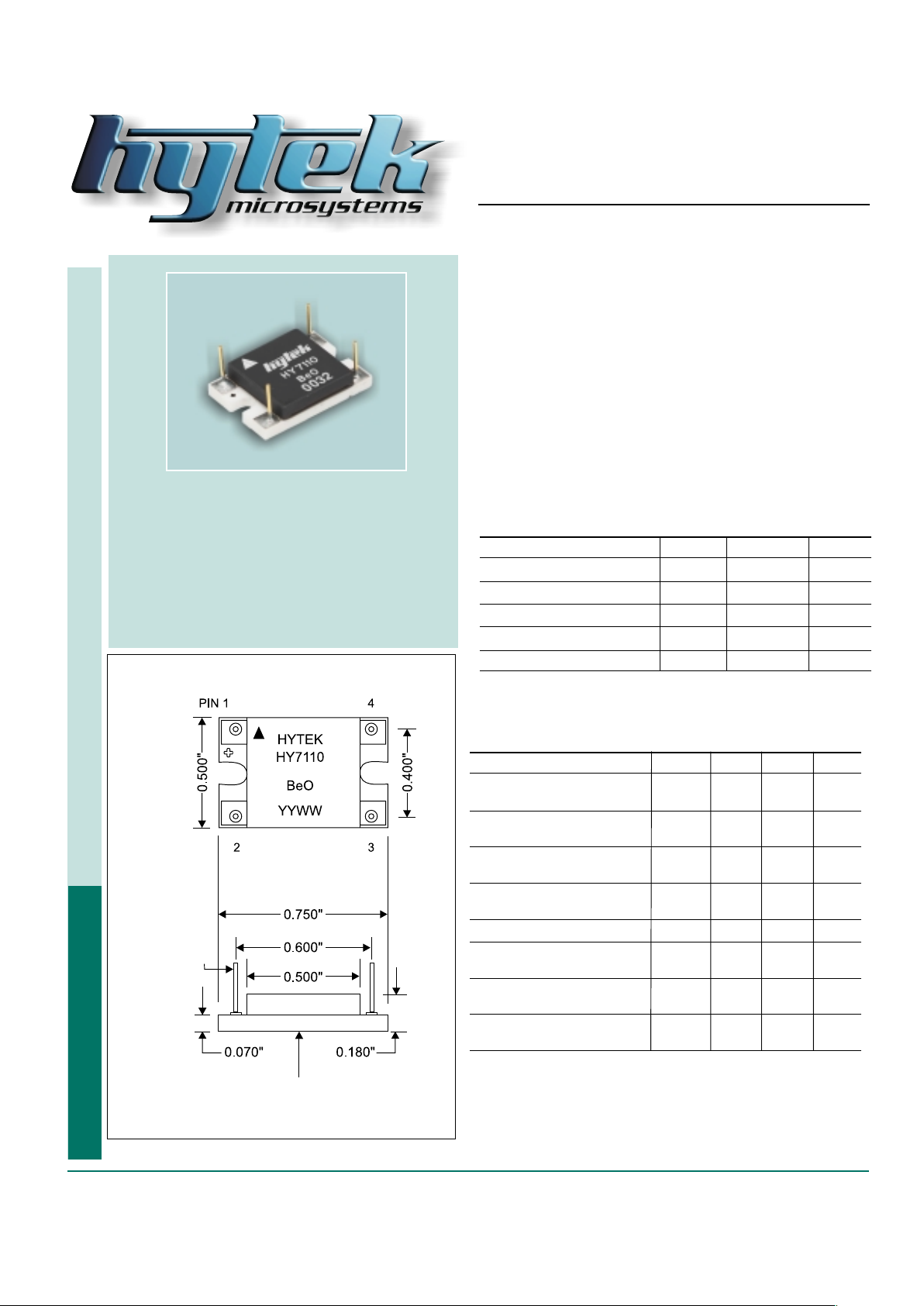
OUTLINE DIMENSIONS
BERYLLIA BASE
TWO TIMES ACTUAL SIZE
0.018" diameter
Cu with Au flash
Features:
✦ Beryllia base for good thermal conduction
✦ Regulation temperature from 40°C to 100°C
✦ Electrically isolated from the case
✦ Epoxy sealed
✦ Hermetically sealed and military screened
units available
Page 2
34 • 400 Hot Springs Road, Carson City NV 89706 • (775) 883-0820 • Fax (775) 883-0827 • www.hytek.com
HY-7110
Micro-Heater
NOTES:
1. Optimum heat transfer between the HY71 10 and the device being heated occurs when a thermal compound, such as
Dow Corning 340, is applied to the mounting surface of the heater.
2. Operation is possible from 100 °C to 120°C, however electrical performance is not guaranteed.
3. Special environmental and electrical screening is available on request.
4. Special custom engineered micro-heater available on request.
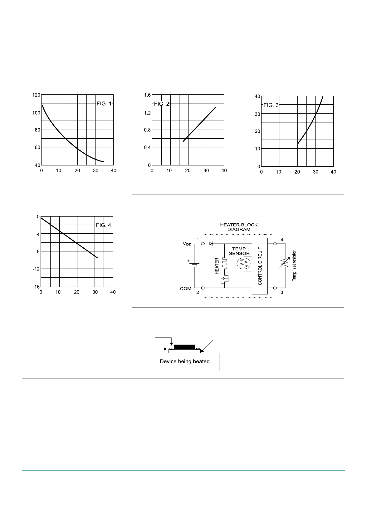
HEATER BLOCK
DIAGRAM
TYPICAL
BASE TEMPERA TURE
VS
CONTROL RESISTOR
BASE TEMPERATURE °C
MAX START-UP CURRENT
VS
SUPPL Y VOLT AGE
SUPPLY CURRENT (AMPS)
MAX THERMAL POWER
AVAILABLE
VS
SUPPL Y VOLT AGE
OUTPUT POWER (WA TTS)
TYPICAL BASE TEMPERATURE
LOSS WITH
POWER DISSIPA TION
TEMPERATURE CHANGE °C
MOUNTING THE HY7110 HEATER
Thermal compound
between surfaces
Do not overtighten the mounting screws.
This may result in breaking the ceramic substrate.
#2-56 mounting
screws
Electrical pin
not shown
for clarity
CONTROL RESISTOR R
C
IN KΩ SUPPLY VOL T AGE (VOL TS D.C.) SUPPLY VOL T AGE (VOL TS D.C.)
POWER OUTPUT (WA TTS)
FROM HY7110
 Loading...