

Page 1
HY6330
Laser Diode Driver
Switchable Constant Current Laser Diode Driver
Features:
✦✦
✦ Adjustable current to 170mA @ 5Volts
✦✦
✦✦
✦ Enable/disable pin
✦✦
✦✦
✦ For common cathode or isolated laser diode
✦✦
current drive
✦ Very small size
✦ Thru-hole or surface-mount package option
Description:
The HY6330 Laser Diode Driver is a program-
mable voltage controlled constant current transconductance amplifier with optical feedback.
The HY6330 is used in applications that require a
stable, selectable current source to drive a laser diode.
The current is selectable from zero to over 170mA. Constant optical output power can be maintained using feedback from a back facet photodetector. Optical output
can also be monitored using the voltage proportional output provided. The HY6330 comes in 10-pin thruhole or
surface mount packages.
The HY6330 is designed for applications requiring
constant current drive for the operation of laser diodes
such as pump sources for EDFA’s telecom lasers, and
diode pumped semiconductors.
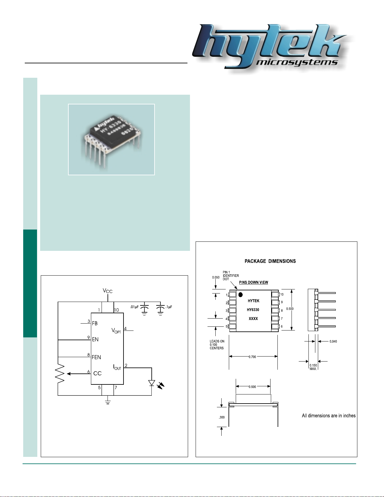
FIGURE 1
TEC Controllers Laser Diode Drivers Micro-heaters
FIGURE 2
28 • 400 Hot Springs Road, Carson City NV 89706 • (775) 883-0820 • Fax (775) 883-0827 • www.hytek.com
Page 2
Laser Diode Driver
Input Specifications
Power Supply Input (VCC): Pins 1, 10 +5 to +8V @250mA max.
Drive Enable (EN): Pin 9 GND (off, disable), VCC or open (on, enable)
Current Control (CC): Pin 6 0 to 200mA for input voltage 0 to VCC
Ground (GND): Pins 5, 7 Power supply ground
Feedback-Optical (FB): Pin 3 0 <FB <VCC
Feedback-Enable (FEN): Pin 8 VCC (disable), GND or open (enable)
Output Specifications
Laser Diode Current Drive (IOUT): Pin 2 0 to 170mA @ 5V, 0 to 250mA @ 8V
Optical Output Monitor (VOPT): Pin 4 Range 0–4V
Environmental Conditions
Operating T emperature –20°C to 100°C (case)
Storage T emperature –65°C to 150°C (case)
Signal Descriptions
HY6330
VCC Input power supply , +5 V olts typical
EN The Enable pin is used to enable/disable the output. When the Enable pin is connected to ground, the
output is disabled. When this pin is connected to VCC or left open, the laser current is enabled, allowing
current to flow through the laser diode.
CC The current is set by the voltage at the current control input. The voltage, on the current control input,
programs the laser diode drive current, IOUT. When the input is at GND the modulation current is zero.
Maximum laser current occurs when this voltage is VCC.
GND Ground return for VCC (input power supply).
FB This high impedance input is used with a photodetector to control Output Current.
FEN At VCC this input disables Feedback on Pin 3, which allows diode current to be set by Pin 6.
IOUT This Output provides drive current to the laser diode; (anode/positive; connect cathode to ground). Maxi-
mum drive current is dependent upon laser diode impedance and power supply input voltage.
VOPT The optical monitor voltage is proportional to the optical output power of the laser diode as sensed by a
backfacet photodetector over the range of 1µA to 1mA.
400 Hot Springs Road, Carson City NV 89706 • (775) 883-0820 • Fax (775) 883-0827 • www.hytek.com • 29
 Loading...