

Page 1
14 • 400 Hot Springs Road, Carson City NV 89706 • (775) 883-0820 • Fax (775) 883-0827 • www.hytek.com
HY5670
TEC Controller Evaluation Board
Thermoelectric Cooler Controller
Evaluation Board
The HY5670 Evaluation Board is a printed cir-
cuit board with an on-board socket which accepts
Hytek's Heat/Cool TEC Controllers (HY5620,
HY5640, or HY5650). It includes the components
needed to make an evaluation temperature controller
for Thermoelectric Coolers. This evaluation board provides the means for a designer to quickly interface
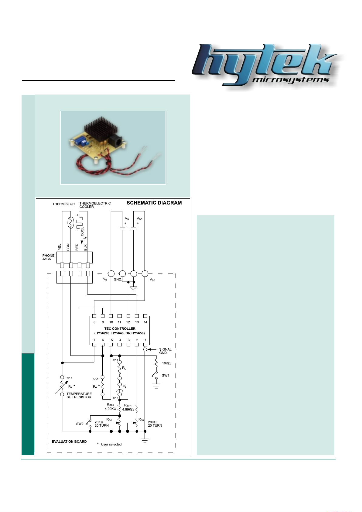
any one of Hytek's bi-polar controllers with a Thermoelectric Cooler and to evaluate performance before designing a printed circuit board. A schematic diagram
for the test board is shown below. The evaluation
board contains loop compensation components of
1µF and 6.8 MΩ (CL and RL). These components can
easily be replaced if it is found that other values are
more suitable. T erminals for the temperature set resistor (RS) are provided on the Evaluation Board for
the user to set the desired TEC temperature.
Procedure for Setting Up the
Evaluation Board
1. Connect a Thermoelectric Cooler and a
Thermistor to the evaluation board as shown in
the schematic diagram. A phone jack along
with interconnect cables is provided for interfacing the Evaluation Board to the Thermoelectric Cooler and Thermistor.
2. Select a Temperature set resistor (R
S) that will
program the controller to regulate the TEC to
the desired temperature. For example: A 56KΩ
resistor will set the TEC to a temperature of
–10°C if a Dale 1M1002, 10KΩ thermistor is
used with the HY5640. See the “Set Temperature vs. Program resistor (R
S)” curve in the
controller Data Sheet to determine the correct
value of R
S for your application. Caution: The
controller will supply maximum programmed
cooling current to the TEC if R
S is not present.
The thermoelectric cooler could be damaged if
this condition exists for a prolonged period of
time.
3. A 1 µF capacitor and a 6.8MΩ resistor have
been selected for the loop stabilization components C
L and RL. These values will more than
likely be satisfactory for most applications.
They can easily be changed if they are not.
(Reference the controller data sheet)
4. There is a position for R
G, the loop gain control
resistor, on the evaluation board. However, this
resistor has been omitted. This is because
there is a 10MΩ resistor internal to Hytek's
controllers that is in parallel with R
G that will, in
most cases, provide sufficient loop gain.
TEC Controllers Laser Diode Drivers Micro-heaters
Figure 1
Page 2
400 Hot Springs Road, Carson City NV 89706 • (775) 883-0820 • Fax (775) 883-0827 • www.hytek.com • 15
HY5670
TEC Controller Evaluation Board
Procedure for Setting Up the HY5670 Evaluation Board
(continued)
5. Connect the VS and VDD power supplies to the test
board. The desired values for these supplies should be
set before the power supplies are connected to the
evaluation board. Note that V
S should be able to supply
more than 2 Amperes of current. Before turning on the
power supplies, make certain the TEC, the Thermistor
and the temperature set resistor (RS) are connected to
the Evaluation Board. In addition, SW1 and SW2 should
be “off.”
6. Turn on the power supplies. The current flowing through
the TEC will either be in a direction to cool the TEC or to
heat it depending on the value of the temperature set
resistor R
S and the temperature of the Thermistor. If RS
is greater in value than the resistance of the thermistor,
the controller will supply maximum cooling current. If RS
is smaller in value than the thermistor the controller will
supply maximum heating current. The controller will
continue to supply maximum heating or cooling current
until the resistance of the Thermistor equals the value
RS. The current supplied by the controller will then
decrease to a value required to maintain the TEC at the
set temperature.
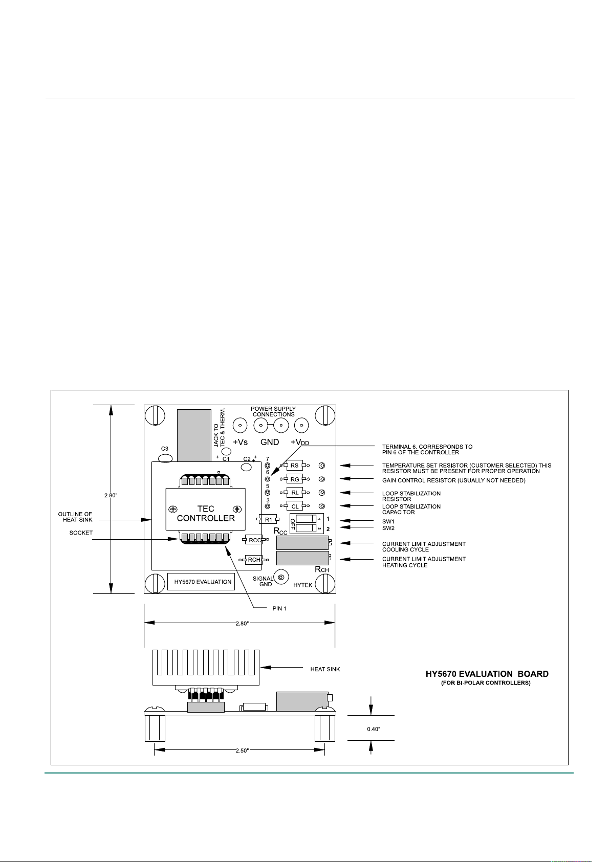
7. Potentiometer R
CC controls the maximum TEC current
in the cooling mode and Potentiometer RCH controls the
maximum current in the heating mode. The Evaluation
Board should be adjusted for the maximum cooling and
heating currents desired for the TEC being used. T o
adjust the cooling current, push Switch #1 to the "on"
position. This action forces the controller to supply
maximum cooling current to the TEC. This maximum
cooling current can then be adjusted to the desired value
with the potentiometer labeled RCC. Do not exceed the
maximum current specification for the TEC. Return SW1
to the “off” position after the adjustment of R
CC. T o
adjust the heating current, push Switch #2 to the “on”
position. This forces the controller to deliver maximum
heating current to the TEC. This maximum heating
current can then be adjusted to the desired value with
the potentiometer labeled RCH. Return SW2 to the “off”
position after the adjustment of RCH. Note that both
SW1 and SW2 must be in the “off” position for normal
operation.
Figure 2
Page 3
16 • 400 Hot Springs Road, Carson City NV 89706 • (775) 883-0820 • Fax (775) 883-0827 • www.hytek.com
HY5670
TEC Controller Evaluation Board
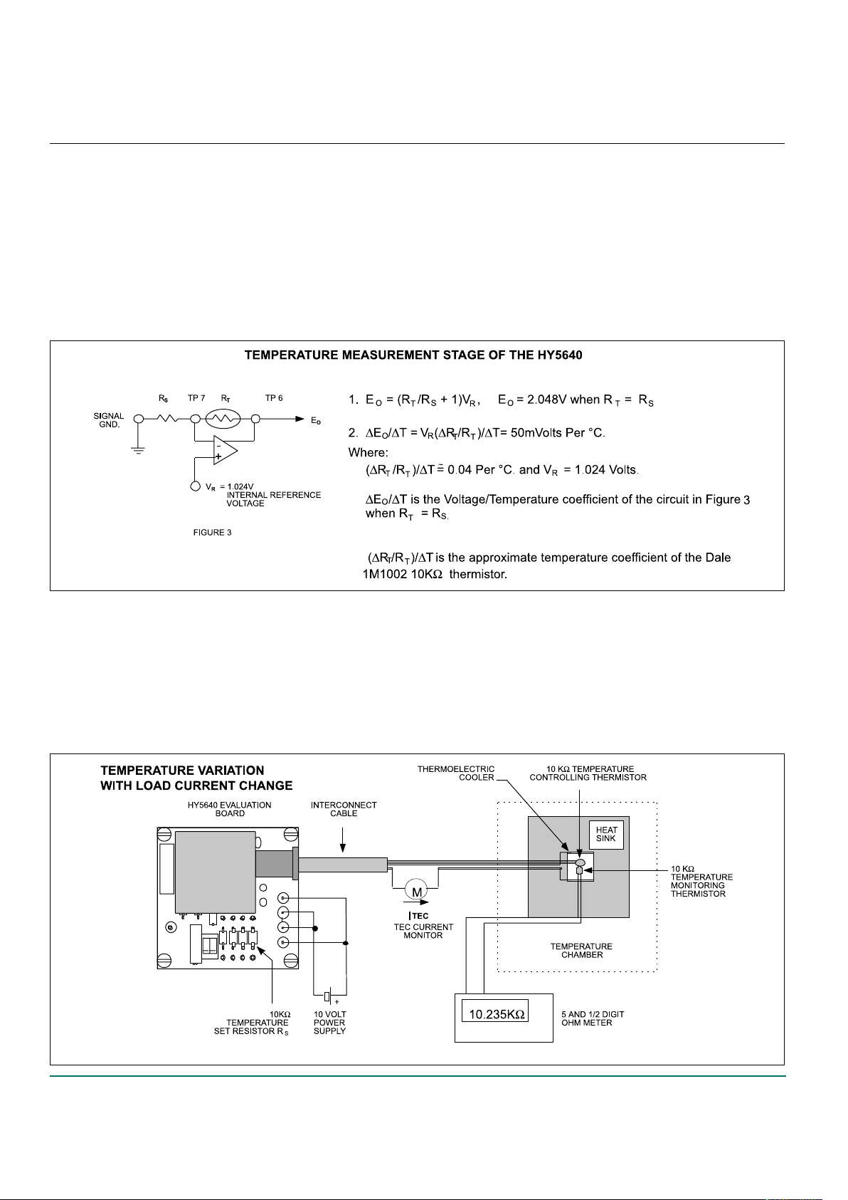
The output of the temperature measuring circuit of the
HY5640 is Pin 6. T est Point 6 on the evaluation board corresponds to this output. The temperature measurement circuit
of the HY5640 is illustrated in Figure 3 where RT is the thermistor that measures the temperature of the Thermoelectric
Cooler and RS is the temperature set resistor. The output
voltage (EO) at T est Point 6 is given by the equation below .
This output feeds the integrator portion of the HY5640 which
in turn applies power to the TEC. Cooling of the TEC results
The temperature controlling stability of the HY5640 vs. Thermoelectric Cooler (TEC) drive current is measured using the
test setup illustrated in Figure 4. The thermoelectric cooler
and temperature sensing thermistor are placed in a temperature chamber. An identical thermistor is mounted in intimate contact with the sensing thermistor. Both thermistors
are embedded in an aluminum block that is attached to the
top surface of the TEC. The bottom face of the TEC is attached to a heat sink. The temperature of the controlling
until RT equals RS. This produces a voltage (EO) of 2.048
Volts between TP 6 and signal ground. The V oltage/T emperature coefficient at TP 6 is approximately 50 mVolts per
°C when this occurs. Monitoring Test Point 6 will tell the
user when the loop is stabilized and how accurately the
temperature is controlled. When the loop has stabilized, the
voltage at TP 6 will be stable to better than 1 mVolt. This
equates to a temperature stability of better than .01 °C.
EXAMPLE: Measuring the Temperature Regulating Performance of the HY5640
thermistor is set to approximately 25°C by selecting an RS
value of 10KΩ. RS is a precision temperature stable resistor .
TEC drive current is monitored as the temperature of the
chamber is increased above 25°C. Resistance of the second thermistor is recorded and converted to temperature for
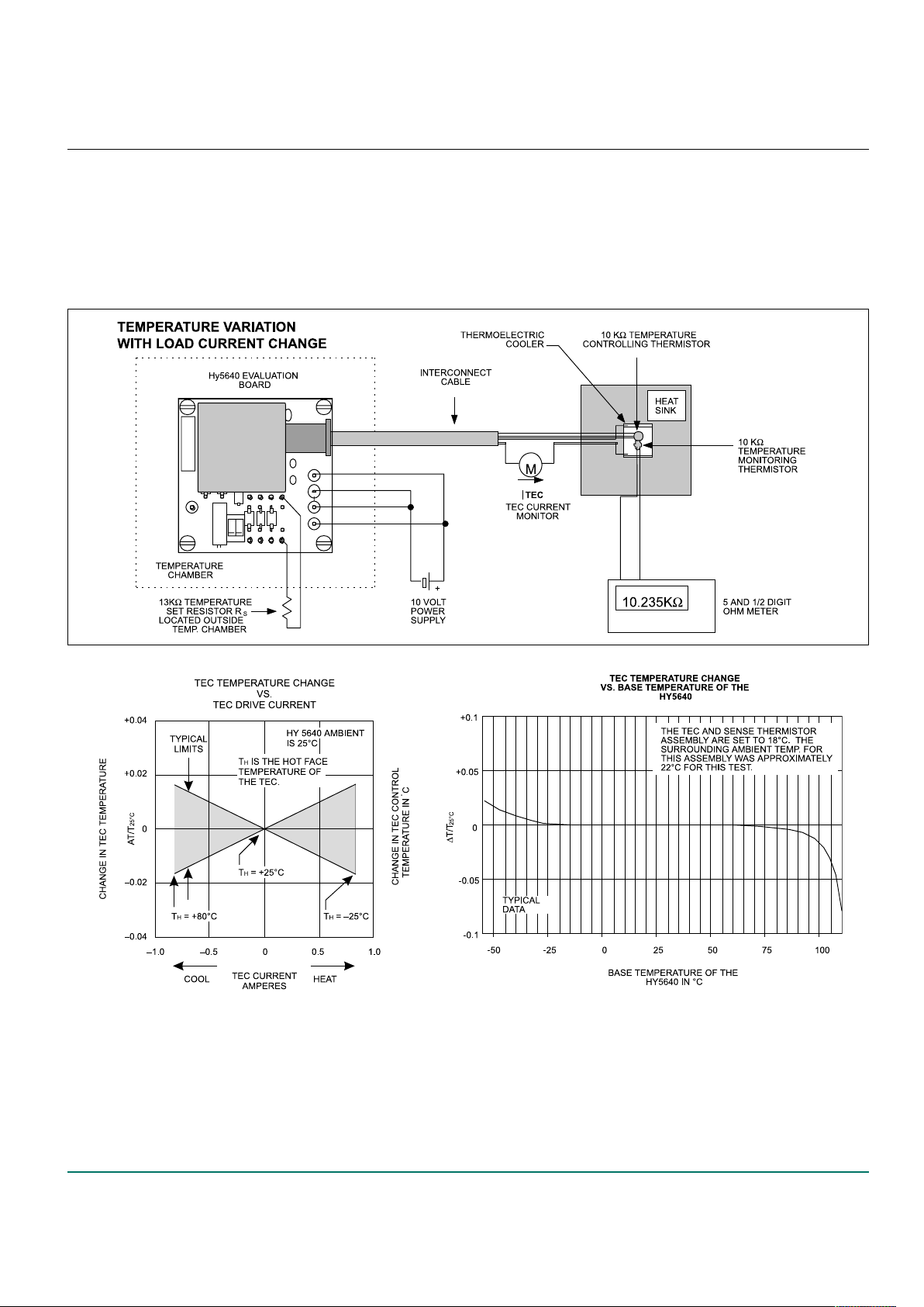
various TEC drive currents. A typical plot of T emperature
stability vs. TEC Drive Current is shown in Figure 6.
Figure 4
Page 4
400 Hot Springs Road, Carson City NV 89706 • (775) 883-0820 • Fax (775) 883-0827 • www.hytek.com • 17
HY5670
TEC Controller Evaluation Board
The temperature controlling stability of the HY5640 vs.
Base T emperature* is measured using the test setup illustrated in Figure 5. The HY5640 is placed inside the temperature chamber. The thermoelectric cooler/thermistor
assembly is placed outside the chamber. In addition, the
13KΩ temperature set resistor RS is located outside the
chamber to eliminate any temperature effects due to this
* Base T emperature is the temperature of the aluminum heat spreader (Base) of the HY5640. In the experiment illustrated
in Figure 5, the programmed temperature of the TEC assembly and its ambient temperature are almost equal. The TEC
current is therefore almost zero amperes thus eliminating any self heating effects in the HY5640. In this case, the temperature of the HY5640 is virtually equal to the temperature of the chamber. In practice, the temperature of the base of
the HY5640 is a function of the TEC drive current, the HY5640 heat sink size, the air flow across the heat sink and the
temperature of the surrounding air.
resistor. This value of RS sets the temperature of the controlling thermistor to approximately 18°C. The temperature
of the test chamber is varied from –55°C to +1 10°C. Resistance of the temperature measuring thermistor is recorded
and converted to temperature. A typical plot of T emperature
stability vs. Base temperature of the HY5640 is shown in
Figure 7.
Figure 5
Figure 6 Figure 7
 Loading...