

Page 1
400 Hot Springs Road, Carson City NV 89706 • (775) 883-0820 • Fax (775) 883-0827 • www.hytek.com • 1
HY5620
TEC Controller
TEC Controllers Laser Diode Drivers Micro-heaters
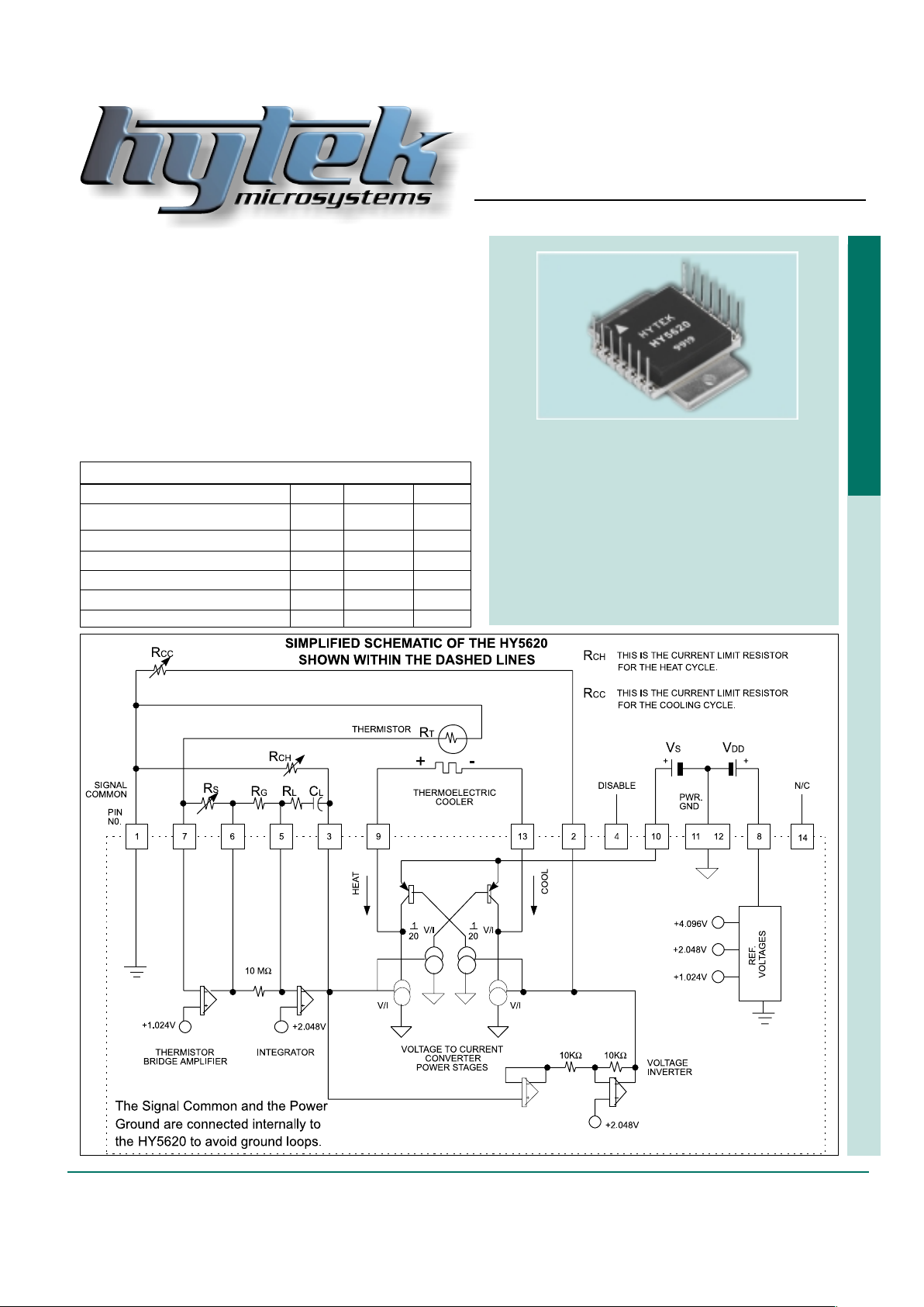
Figure 1
Subminiature Controller for
Thermoelectric Coolers
(Grounded Thermistor)
The HY5620 is a subminiature proportional temperature
controller for thermoelectric coolers (TEC). This device is intended for “heat or cool” fixed temperature applications where
front panel controls and digital readouts are not required. The
HY5620 uses a thermistor bridge to precisely measure and
regulate the temperature of a device affixed to a TEC. With
proper heat sinking, the power stage of this device will deliver
up to +/- 2 Amperes of current to a TEC. This controller was designed for a grounded thermistor configuration. In addition, the
device can be operated with dual supplies where Vs can be as
low as +3V and V
DD as low as +5V.
Features:
✦ Proportional/Integral (PI) control
✦ Small size
✦ Drive current to +/–2 amps
✦ Operation to 12 volts
✦ Control above/below ambient
✦ T emperature stability of 0.01°C
✦ Single supply operation
✦ Thru-hole or surface-mount packaging option
✦ Digital Enable/Disable Control
Maximum ratings:
Rating Symbol Value Unit
Supply Voltage 1 (Voltage on Pin 8) VDD +20 Volts DC
Supply Voltage 2 (Voltage on Pin 10) VS +12 Volts DC
Current Sink (Heat and Cool Cycle) Is 2.5 Amperes
Maximum Power Dissipation PMAX 6 Watts
Operating Temperature (Case) TMAX/MIN 100/–20 °C
Storage Temperature TSTG –65 to +150 °C
Page 2

2 • 400 Hot Springs Road, Carson City NV 89706 • (775) 883-0820 • Fax (775) 883-0827 • www.hytek.com
HY5620
TEC Controller
•
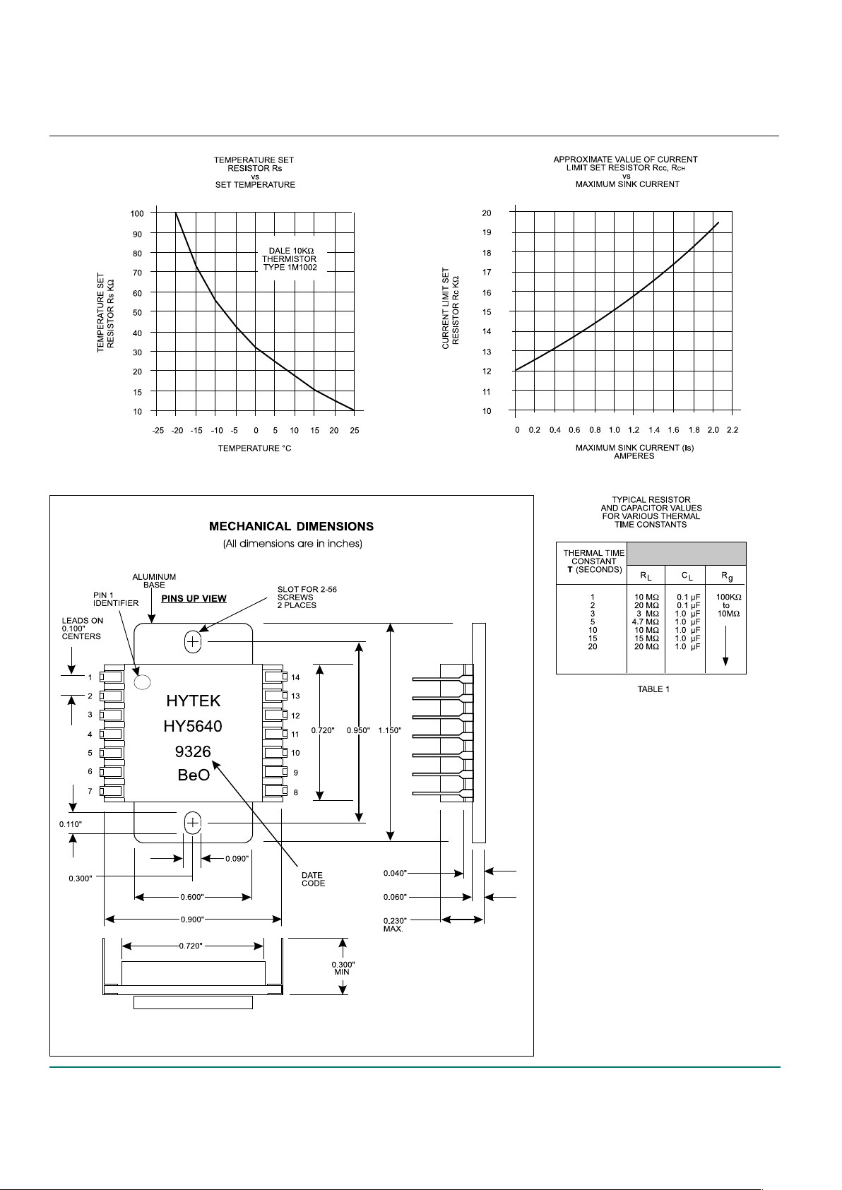
Temperature Set Resistor Rs (Pin 6 to Pin 7)
The temperature set resistor for the HY5620 controls the
temperature at which the TEC will operate. When the circuit has stabilized, the resistance of the thermistor will
be equal to that of the set resistor Rs. For example, if a
Dale 10KΩ thermistor is used as the temperature sensing device, a set resistor of approximately 56KΩ will set
an operating temperature of –10°C. A graph of Rs vs. set
temperature is shown in figure 4 when using a Dale
1M1002 thermistor.
• Thermistor, RT (Pin 1 to Pin 7)
The thermistor should be located in close proximity to
the device being temperature controlled by the TEC. It
should be in good thermal contact to avoid stability problems. The thermistor ground must be connected to Pin 1.
The HY5620 has been designed for a negative temperature coefficient (NTC) thermistor . A thermistor with a
positive temperature coefficient can be used by reversing
the leads of the TEC in which case Rcc and RCH must
be interchanged.
• Gain Set Resistor, RG (Pin 5 to Pin 6)
The ratio of the gain set resistor RG to RL controls the
response time of the servo loop. A ratio that is too large
can cause slow response and a ratio that is too small
can cause loop instability. In most applications R G may
not be needed since a 10MΩ resistor is internal to the
HY5620 and generally provides enough gain for good operation.
• Loop Stability Network, RL and C
L
(Pin 3 to Pin 5)
The RC time constant of these two components is a first
approximation of the thermal time constant of the servo
loop. The thermal time constant of the combination of the
device being cooled, the thermistor, and the TEC can be
approximated by applying constant power to the TEC
and measuring the length of time it takes to reach 66%
of its final temperature.
For example, if the thermal time constant was observed to be 5 seconds, then a 1µF capacitor and a
4.7MΩ could be chosen as the loop stabilizing components. Typical values for loop compensation components
are shown in T able 1.
Note: The values of RG, RL, and CL are generally selected
by experiment. CL should be a low leakage
nonpolarized capacitor.
• Current Limit Resistors, RCH & R
CC
(Pin 1 to Pin 3, and Pin 1 to Pin 2)
These resistors limit the maximum current that the
HY5620 can supply to the TEC when in the cooling
cycle and in the heating cycle. Rcc limits the maximum
current for the cooling cycle and RCH limits the maximum current in the heating cycle. This feature prevents
damage to the TEC during turn on. It is often desirable
to limit the maximum value of heating current as much
as 30% less than the maximum cooling current. This is
because TECs are much more efficient heating than
cooling. Figure 5 shows the approximate values for Rcc
and RCH required to program a desired turn on current.
For example, an Rcc value of 17KΩ will limit the maximum cooling current to 1.5 Amperes and an RCH value
of 13.5KΩ will limit the maximum heating current to 0.5
Amperes.
• VDD (Pin 8 to Pins 11 & 12) +5 < VDD < +20 Volts
This input supplies the voltage to the internal circuitry of
the HY5620. The maximum current drain at this terminal
is 5mA.
• Vs (Pin 10 to Pins 11 & 12) +3 < Vs < +12 Volts
This input supplies the voltage to the HY5620 power drive
circuitry . The maximum current drain at this terminal
should not exceed 2 Amperes. Note that VDD and VS can
be driven with the same power supply in the range of +5V
< VDD = VS <+12V.
Ideally VS is no more than 1.5V higher than the VMAX
of the selected TEC. Setting VS higher than this can
cause excessive heating of the controller.
• Thermoelectric Cooler, TEC (Pin 9 to Pin 13)
The cooling lead of the TEC should be connected to Pin
13 and the heating lead should be connected to Pin 9 of
the HY5620. If the temperature of the thermistor is
greater than the set temperature at turn on, maximum
cooling current will flow into Pin 13 and out of Pin 9.
Conversely , maximum heating current will flow into Pin
13 and out of Pin 9 if the temperature of the thermistor is
less than the set temperature at turn on. The maximum
turn on current is limited by Rcc and RCH. Once the TEC
reaches its set temperature, the current through the TEC
will decrease to exactly the value required to maintain
the correct set temperature.
Description of the HY5620 Pin Outs
• Disable (Pin 4)
The TEC current can be disabled by applying a TTL
high (+5V) to Pin 4 of the HY5620. The HY5620 is enabled when Pin 4 is connected to ground or left open (no
connection).
Page 3
400 Hot Springs Road, Carson City NV 89706 • (775) 883-0820 • Fax (775) 883-0827 • www.hytek.com • 3
HY5620
TEC Controller
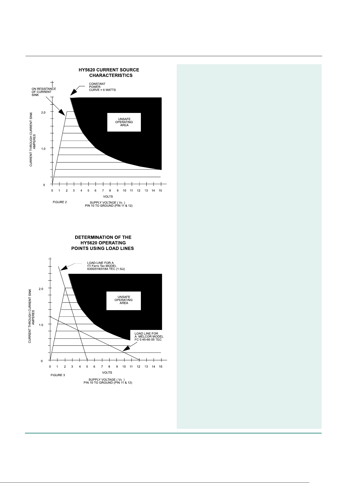
Figure 2 illustrates the characteristics of
the HY5620 power drive section. It also
illustrates the unsafe operating area
where the power dissipated in the device
exceeds the maximum 6 Watt rating.
This curve applies for both heating and
cooling operation.
Note that the resistance of the power
drive section is approximately one ohm
when the HY5620 is fully turned on.
Figure 3 illustrates the locus of operating
current and voltage for two different TECs.
Example 1:
A supply voltage of 5 Volts was chosen for
use with the ITI Ferro T ek Model
6300/018/018A TEC. This device is rated for
a maximum current of 1.8 Amperes at a
maximum allowable voltage of 2.7 Volts.
This is a load resistance of approximately
1.5 ohms. The intersection of the 1.5 ohm
load line and the HY5620 current source
characteristics defines the locus of operation
voltage and current for both the HY5620
and the TEC. In this application the current
was limited to 1.8 Amperes when cooling and
to 0.6 Amperes when heating by proper
selection of RCC and RCH.
Example 2:
A supply voltage of 12 Volts was chosen for
the Melcor FC 0.45-66-05 TEC. This device
has a maximum rated voltage of 7.98 Volts
at a current of 0.8 Amperes. A load line for
this device is also shown on the plot. Once
again maximum turn on current is set by
proper selection of RCC and RCH.
Note that the power dissipated in the HY5620
never exceeds the 6 Watt maximum
power dissipation in both of these examples.
Page 4
4 • 400 Hot Springs Road, Carson City NV 89706 • (775) 883-0820 • Fax (775) 883-0827 • www.hytek.com
HY5620
TEC Controller
Figure 4
Figure 6
Figure 5
NOTES:
1. Make certain the heat sink to which
the HY5620 is mounted is flat and
clean, otherwise the ceramic
substrate may break.
2. Use a thermal compound such as
Dow Corning 340 between the
HY5620 and the heat sink for good
thermal conduction.
3. Note that the Pin 1 identifier is shown
in a bottom view. From a top view, Pin
numbers ascend in clockwise
fashion.
Specifications subject to change without
notice.
 Loading...