

Page 1
❇
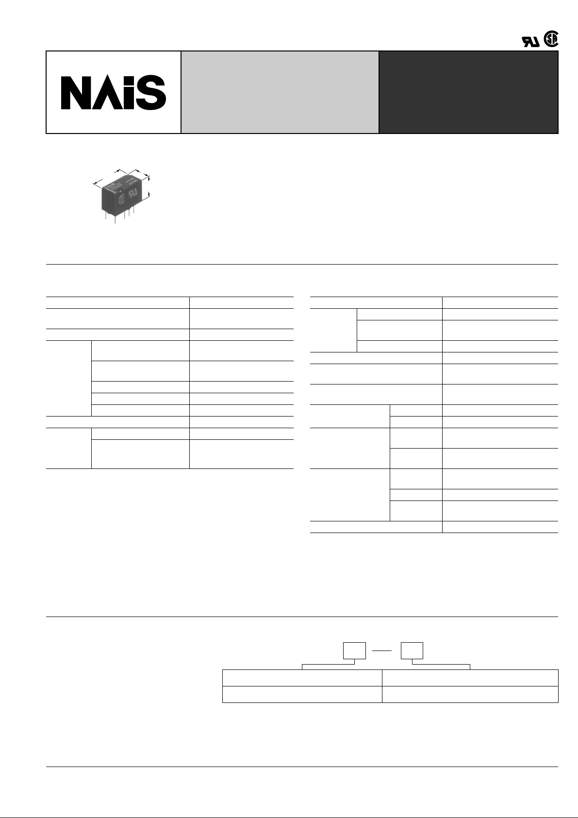
Compact & Slim 2 Form C
Non-polarized Relay
HX-RELAYS
FEATURES
15.0
.591
7.4
.291
9.4
.370
• Compact size of (W) 7.4 × (L) 15.0 × (H)
9.4 mm (W) .291 × (L) .591 × (H) .370
inch.
• Surge withstand voltage of 1,500 V
(between contact and coil)
Conforms to FCC Part 68.
mm inch
• High-density mounting is possible
• High reliability
The use of a gold-clad bifurcated structure for the movable contacts, and a low
gas material for the forming materials and
coil wiring ensures high contact reliability.
SPECIFICATIONS
Contact
Arrangement 2 Form C
Initial contact resistance
(By voltage drop 6 V DC 1 A)
Contact material Gold-clad silver alloy
Nominal switching
capacity (resistive load)
Max. switching power
Rating
(resistive load)
Max. switching voltage 110 V DC, 125 V AC
Max. switching current 1 A
Min. switching capability ❇ 1
Nominal operating power 320 mW
Expected
life (min.
operations)
Mechanical (at 180 cpm) 10
Electrical (at 20 cpm)
Note:
1This value can change due to the switching frequency, en vironmental conditions,
and desired reliability level, therefore it is recommended to chec k this with the actual load.
Remarks
* Specifications will vary with foreign standards certification ratings.
1
*
Measurement at same location as "Initial breakdown voltage" section.
2
By resistive method, nominal voltage applied to the coil; contact carrying current:
*
1A.
3
Nominal voltage applied to the coil, excluding contact bounce time.
*
4
*
Half- wave pulse of sine wave: 11ms, detection time: 10 µ s
5
Half- wave pulse of sine wave: 6ms
*
6
*
Detection time: 10 µ s
7
*
Refer to 5. Conditions for operation, transport and storage mentioned in
AMBIENT ENVIRONMENT (Page 61)
Max. 100 m Ω
1 A 30 V DC, 0.3 A 125 V AC
30 W (DC), 37.5 VA (AC)
1 mA 1 V DC
7
5
10
(1 A 30 V DC,
0.3 A 125 V AC resistive)
Characteristics
Initial insulation*
Initial
breakdown
voltage
Temperature rise*
Operate time*
(at 20 ° C 68 ° F)
Release time(without diode)*
(at 20 ° C 68 ° F)
Shock resistance
Vibration resistance
Conditions for
opetation, transport
and storage*
Unit weight Approx. 2g .07 oz
1
resistance Min. 1,000 M Ω (at 500 V DC)
Between contacts 750 V rms for 1 min.
Between contact and
coil
1,000 V rms for 1 min.
Between contacts sets 1,000 V rms for 1 min.
2
3
3
Functional*
Destructive*
Functional*
Destructive
4
5
6
at double amplitude of 1.0 mm
at double amplitude of 1.5 mm
Ambient
temperature
7
Humidity 5 to 85% R.H.
Atmospheric
pressure
Max. 60 ° C
Max. 6 ms (Approx. 4 ms)
Max. 5 ms (Approx. 3 ms)
Min. 100 m/s
Min. 1,000 m/s
2
{10G}
2
{100G}
10 to 55 Hz
10 to 55 Hz
–40 to +70 ° C
–40 to +158 ° F
86 to 106 kPa
TYPICAL
APPLICATIONS
• Telephone exchange, transmission
equipment
• Communications devices
• Measurement devices
• Home appliances, and audio/visual
equipment
• Office equipment
ORDERING INFORMATION
Ex. HX 2 3V
Contact arrangement Coil voltage(DC)
2: 2 Form C 1.5, 3, 4.5, 5, 6, 9, 12, 24 V
Note: 2,500V Surge (Bellcore) type is also available.
Please consult us for details.
183
Page 2
HX
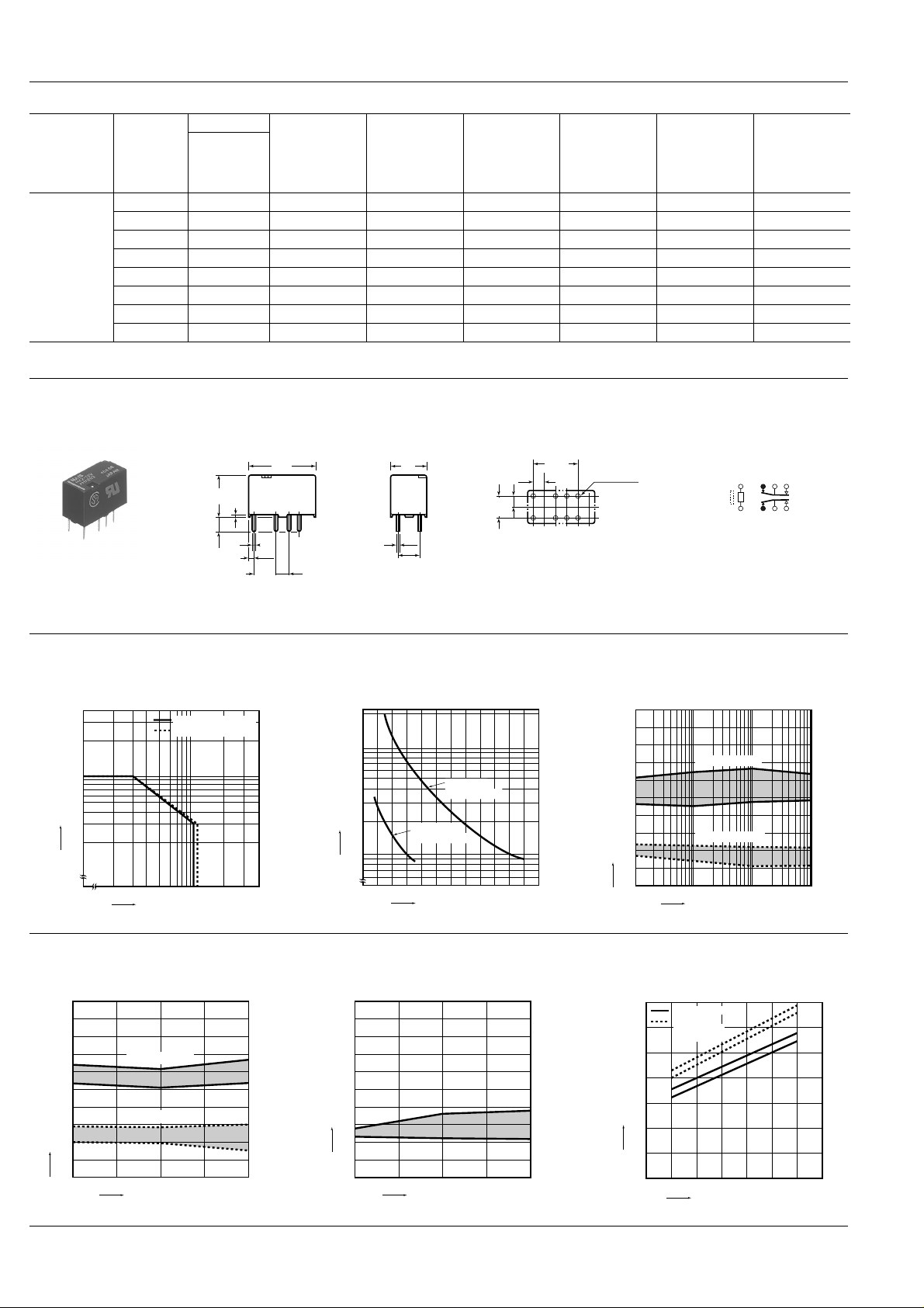
TYPES AND COIL DATA
Part No.
Contact
arrangement
Coil rating,
V DC
1.5 HX2-1.5V 1.13 0.15 214 7.0 320 1.65
3 HX2-3V 2.25 0.3 107 28.1 320 3.3
4.5 HX2-4.5V 3.38 0.45 71.1 63.3 320 4.95
2 Form C
5 HX2-5V 3.75 0.5 64.0 78.1 320 5.5
6 HX2-6V 4.5 0.6 53.6 112 320 6.6
9 HX2-9V 6.75 0.9 35.6 253 320 9.9
12 HX2-12V 9 1.2 26.7 450 320 13.2
24 HX2-24V 18 2.4 13.3 1,800 320 26.4
Standard packing: Tube; 40 pcs.; Case : 1,000 pcs.
Standard
PC board
terminal
arrangement
Pick-up
voltage,
V DC (max.)
(at 20 ° C 68 ° F)
V DC (min.)
(at 20 ° C 68 ° F)
Drop-out
voltage,
(at 20 ° C 68 ° F)
Normal
operating
current,
mA ( ± 10%)
Resistance,
ohm ( ± 10%)
(at 20 ° C 68 ° F)
Coil
Nominal
operating
power,
mW
Max. allowable
voltage,
V DC
(at 70 ° C 158 ° F)
DIMENSIONS
1. Standard PC board terminal type
9.4
0.45
.370
.018
3.5
.138
1.15
.138
General tolerance: ± 0.3 ± .012
0.5
.020
5.08
.200
15.00
.591
2.54
.100
0.25
.010
7.4
.291
5.08
.200
PC board pattern (Bottom view)
10.16
5.08
.200
2.54
.100
.400
2.54
.100
8-1 dia
8-.039 dia
T olerance: ± 0.1 ± .004
REFERENCE DATA
1. Maximum switching capacity 2. Life curve 3. Mechanical life
3.0
2.0
1.0
0.5
0.4
Switching current, A
0.3
0.2
20 30 50 100 200 300
Switching voltage, V
DC load (cos ϕ = 1)
AC load (cos ϕ = 1)
200
4
100
50
30
20
No. of operations, ×10
10
0.2 0.4 0.6 0.8 1.0 1.2
30 V DC
resistive load
125 V AC
resistive load
Switching current, A
Tested sample: HX2-12 V, 10 pcs.
100
90
80
70
60
50
40
30
20
Ratio against the rated voltage, %V
10
0
mm inch
Schematic (Bottom view)
112310495
8
Pick-up voltage
Drop-out voltage
100 500 1,000
No. of operations, ×10
4
Max.
Min.
Max.
Min.
4. Electrical life (1 A 30 V DC resistive load)
Tested sample: HX2-12 V, 6 pcs.
Operating frequency: 20 cpm
Change of pick-up and drop-out voltage Change of contact resistance
100
90
80
70
60
50
40
30
20
Ratio against the rated voltage, %V
10
0
Pick-up voltage
Drop-out voltage
510
No. of operations, ×10
Max.
Min.
Max.
Min.
4
Contact resistance, mΩ
100
90
80
70
60
50
40
30
20
10
0
510
No. of operations, ×10
184
5. Coil temperature rise
Tested sample: HX2-12 V
Measured portion: Inside the coil
Ambient temperature: 25 ° C 77 ° F, 70 ° C 158 ° F
70
70°C 158°F
Room
temperature
60
(25°C 77°F)
50
40
Max.
Min.
4
30
Temperature rise, °C
20
10
0
100 110 120 130 140 150
Coil applied voltage, %V
1 A
0 A
1 A
0 A
Page 3
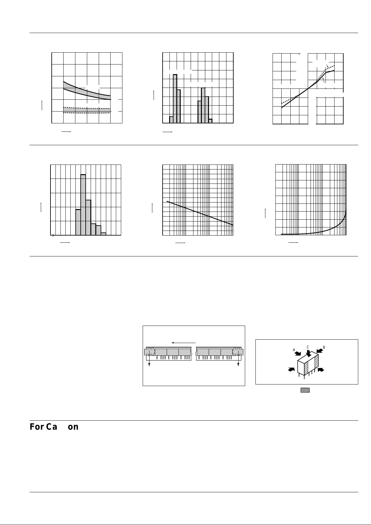
6. Operate/release time characteristics
Pick-up voltage
Drop-out
voltage
Variation ratio, %
Ambient temperature, °C
0–20–40
–10
–20
–30
–40
–10
–20
–30
–40
4020 60 80
A
C
B
Tested sample: HX2-12V, 10 pcs.
6
5
4
3
Set/reset time, msec.
2
1
0
80 90 100 110 120
Set time
Reset time
Coil applied voltage, %V
Max.
Min.
Max.
Min.
7. Distribution of pick-up and drop-out voltage
Tested sample: HX2-12V, 50 pcs.
35
30
Drop-out voltage
25
Quantity
20
15
10
5
0
10 20 30 40 50 60 70 80 90 100
Pick-up voltage
Ratio against the rated voltage, %V
8. Ambient temperature characteristics
Tested sample: HX2-12V, 5 pcs.
HX
9. Distribution of contact resistance
Tested sample: HX2-12V, 25 pcs. (25 × 4 contacts)
50
40
30
Quantity
20
10
0
20 30 40
Contact resistance, mΩ
NOTES
1. Coil operating power
Pure DC current should be applied to the
coil. The wav e form should be rectangular.
If it includes ripple, the ripple factor should
be less than 5%.
However, check it with the actual circuit
since the characteristics may be slightly
different. The nominal operating voltage
should be applied to the coil for more than
10 ms to set/reset the latching type relay.
2. Cleaning
In automatic cleaning, cleaning with the
boiling method is recommended. A v oid ultrasonic cleaning which subject the relay
to high frequency vibrations. It may cause
the contacts to stick.
lt is recommended that a fluorinated hydrocarbon or other alcoholic solvent be
used.
10.-(1) High frequency characteristics
Isolation characteristics
100
Isolation, dB
50
10 100 1,000
Frequency, MH
Z
3. Packing style
• Packing direction
The relay is packed in a tube with the rela y
orientation mark on the left side, as shown
in the figure below.
Take note of the relay orientation when
mounting relays on the printed circuit
board.
Orientation (indicates PIN No. 1) stripe
Stopper
(gray)
Stopper
(green)
The temperature range is –40 to +70 ° C
–40 to +158 ° F
10.-(2) High frequency characteristics
Insertion loss characteristics
0.5
0.4
Insertion loss, dB
0.3
0.2
0.1
0
10 100 1,000
Frequency, MH
Z
4. Automatic insertion
To maintain the internal function of the relay, the chucking pressurre should not exceed the values below.
Chucking pressure in direction A:
9.8 N {1 kgf} or less
Chucking pressure in direction B:
9.8 N {1 kgf} or less
Chucking pressure in direction C:
4.9 N {500 gf} or less
Please chuck the portion.
Avoid chucking the center of the relay.
For Cautions for Use, see Relay Technical Information (Page 48 to 76).
185
Go To Online Catalog
9/1/2000 All Rights Reserved, © Copyright Matsushita Electric Works, Ltd.
 Loading...