

Page 1
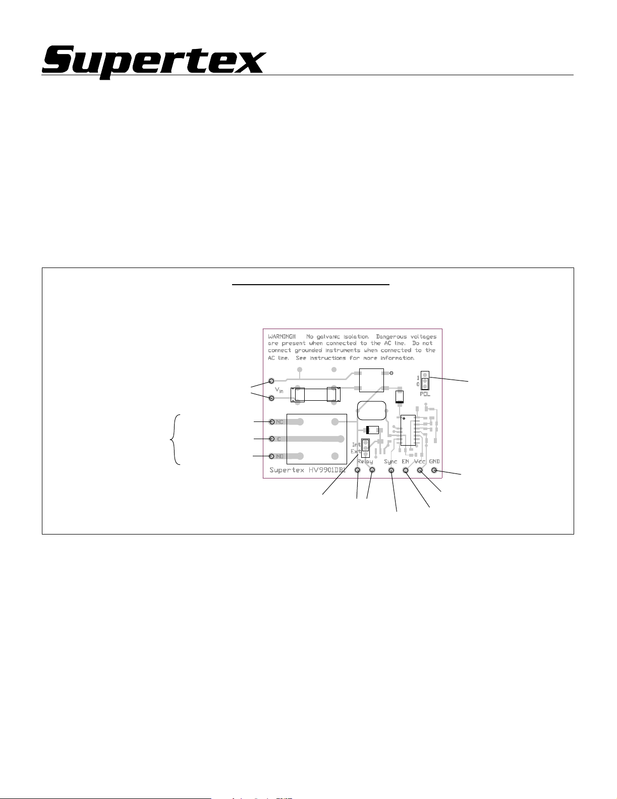
HV9901DB1
Universal Relay Driver
Introduction
The HV9901 is a universal relay driver employing PWM
switching techniques utilizing the relay coils inductance to
provide efficient operation over a wide supply voltage range.
Relay drive is constant-current. Pull-in current, pull-in time,
and hold current are all programmable via 2 resistors and a
capacitor. An adjustable regulator provides 1mA for external
circuitry.
The HV9901DB1 demo board contains all the circuitry
necessary to demonstrate the operation of the HV9901.
Included on-board are a full-wave input rectifier, fuse, the
HV9901, and a 10A relay. Provisions for connecting an
external relay are available. The circuit may be modified to
accomodate the drive requirements of other relays.
WARNING!!!
Board Layout and Connections
Do not connect earth-grounded
instruments when connected to the
AC line. Doing so will short the AC
line, resulting in damage to the demo
board and/or the instrument. Use an
isolation transformer on the AC line,
use high voltage differential probes,
or use a floating instrument to make
measurements when connected to
the AC line.
Input
Voltage
Normally Closed
Relay
Contacts
Common
Normally Open
Specifications
Input Voltage 10400VDC, 24277VAC
Relay Drive Current 72mA pull-in, 24mA hold
Pull-in Time 20ms
Contact Form SPDT (1FormC)
Contact Rating 10A@125VAC, 6A@277VAC
Auxillary Regulator (V
) 5.0V@1mA
CC
Enable <1.5V off, >3.5V on
Switching Frequency 21kHz
~
D1
~
F1
K1
+
D2
C1
D3
Q1
C2
C4
R1
R2
IC1
R4
R5
R3
C5
R6
C3
R7
Enable Polarity
Selector
WARNING!!!
No galvanic isolation. Dangerous voltages
are present when connected to the AC line.
Input Voltage
Supply voltage. May be a DC source in the range of
10400VDC, or an AC source in the range of 24277VACrms.
A full-wave bridge rectifier on board rectifies the AC. Also
included is a 250mA 2AG fuse.
Relay Contacts
For connecting an external load. The PCB traces are rated at
10A for a 20°C rise.
Relay Selector
In the Int position, the on-board relay is operated. In the Ext
position, a relay connected to the External Relay terminals is
operated.
External Relay
For connection of an off-board relay.
Relay
Selector
Ground
V
External
Relay
Sync
Enable
CC
Sync
Synchronizes multiple HV9901s to the same frequency or to a
master clock. Frequency will be the highest independent
frequency. Connect to the Sync pins of other HV9901s or to a
master clock.
Enable
Logic-level enable for relay operation. See Enable Polarity
Selector for polarity.
V
CC
Supplies 5V at 1mA for external circuitry.
Ground
Circuit common. Since galvanic isolation is not provided,
ground will be at the AC line potential!
Enable Polarity Selector
Sets Enable polarity. In the 0 position, Enable is active low. In
the 1 position, Enable is active high.
Page 2
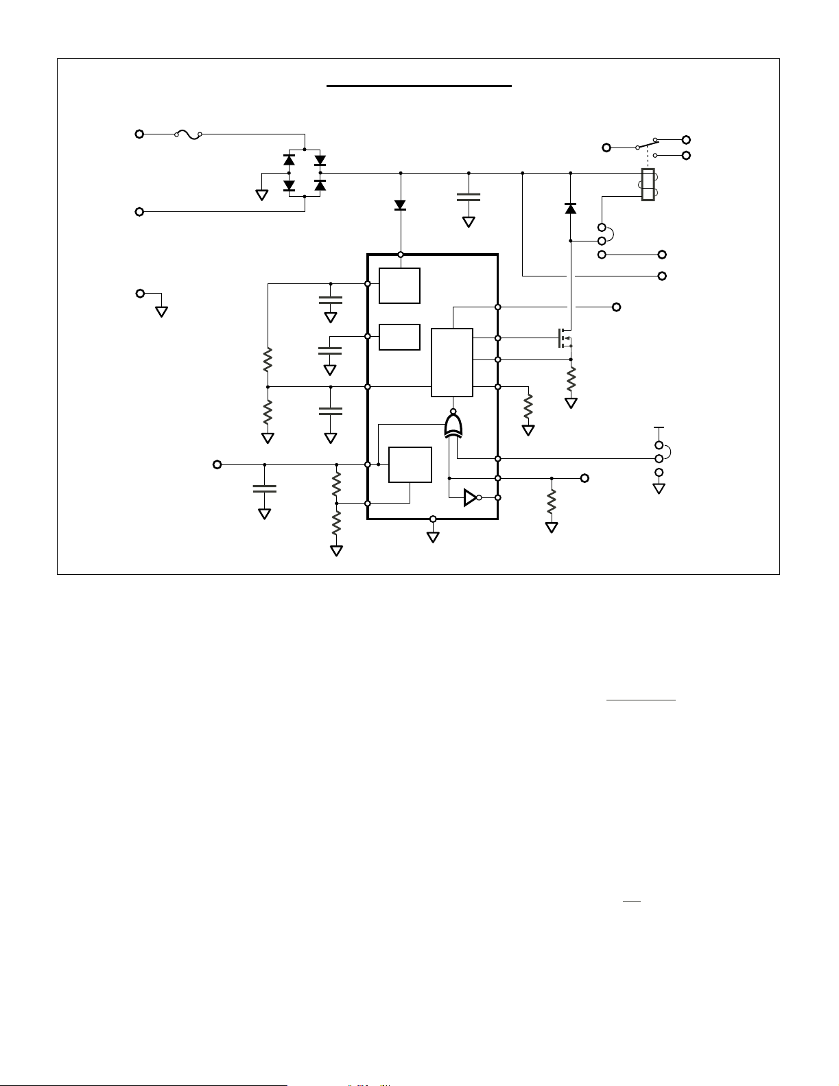
HV9901DB1 Schematic
F
1
250mA
V
IN
D
1
DF06
D
S1J
C
C
2
VIN
100nF
1
D
ES1J
3
INT
EXT
RELAY
NC
NO
K
1
NAIS JS1-5V
VDD
GND
V
CC
5.0V @ 1mA
226kΩ
8.25kΩ
C
1.0µF
R
1
R
2
5
C
4.7µF
100nF
1.0µF
374kΩ
124kΩ
2
VREF
C
3
H/D
C
4
VCC
R
3
R
4
Modifications
External Relay
Connect the coil of the external relay to the External Relay
terminals and move the Relay Selector shunt to the Ext
position.
Pull-in Current, Pull-in Time, and Hold Current
For use with other relays, these parameters may be changed
via resistors R
data sheet for details.
and R2 and capacitor C4. Refer to the HV9901
1
Int
Reg
V
REF
Aux
Reg
PWM
SYNC
GT
CS
RT
POL
ENI
ENOFB
R
6
1.21MΩ
R
270kΩ
Q
VN2450
R
11Ω
7
1
5
EN
SYNC
V
CC
1
POL
0
Switching Frequency
To change the PWM switching frequency, change R
to the following equation:
f
PWM
=
3.23kHz
21.8GHz
+
⋅
Ω
R
6
This equation is valid for frequencies 25kHz and above. Be
advised that frequencies below 20kHz may cause the relay coil
to emit audible noise. And avoid higher frequencies that
approach the coils resonant frequency.
according
6
Monitoring Relay Current
For the on-board relay, coil current may be monitored by
replacing the Relay Selector shunt with either a wire loop (for
current probe use) or with a low value sense resistor (for
voltage probe use). Remember that galvanic isolation is not
provided! See warnings on the first page.
V
CC
As provided, the HV9901DB1 supplies 5V for external circuitry.
Other volltages in the range 2.0V to 5.5V may be obtained by
changing R
Note that changing V
. Current rating remains at 1mA.
3
V
CC
CC
also changes the Enable logic levels.
<
3.0
)(
>
7.0
)(
R
3
+=
1V25.1
R
4
VV
CCloEN
VV
CChiEN
 Loading...