

Page 1
High-Voltage Current-Mode PWM Controller
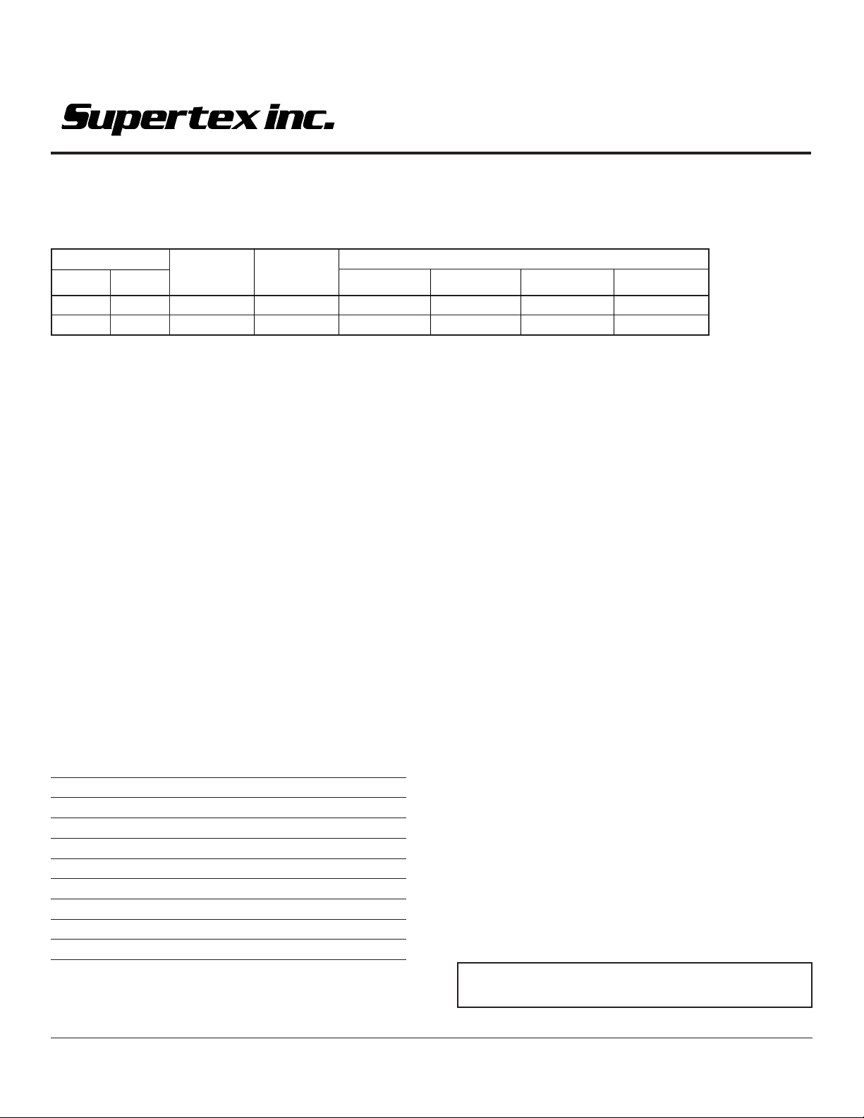
Ordering Information
HV9120
HV9123
+V
IN
Min Max
10V 450V <±2% 49% HV9120P HV9120NG HV9120PJ HV9120X
10V 450V <±2% 99% HV9123P HV9123NG HV9123PJ HV9123X
Standard temperature range for all parts is industrial (-40° to +85°C).
Feedback Max
Accuracy Duty Cycle
16 Pin 16 Pin 20 Pin
Plastic DIP SOIC Plastic PLCC
Features
❏ 10 to 450V input acceptance range
❏ <1.3mA supply current
❏ >1.0MHz clock
❏ >20:1 dynamic range @ 500KHz
❏ Low internal noise
Applications
❏ Off-line high frequency power supplies
❏ Universal input power supplies
❏ High density power supplies
❏ Very high efficiency power supplies
❏ Extra wide load range power supplies
Absolute Maximum Ratings
Voltages are referenced to -V
+VIN Input Voltage 450V
VDD Device Supply Voltage 15.5V
Logic Input Voltages -0.3 to VDD + 0.3V
Linear Input Voltages -0.3 to VDD + 0.3V
IIN Preregulator Input Current (continuous) 2.5mA
Tj Operating Junction Temperature 150° C
Storage Temperature -65°C to 150°C
Power Dissipation, PDIP 1000mW
Power Dissipation PLCC 1400mW
Power Dissipation SOIC 900mW
IN
Package Options
General Description
The Supertex HV9120 and HV9123 are Switch Mode Power
Supply (SMPS) controller subsystems that can start and run
directly from almost any DC input, from a 12V battery to a rectified
and filtered 240V AC line. They contain all the elements required
to build a single-switch converter except for the switch, magnetic
assembly, output rectifier(s) and filter(s).
A unique input circuit allows the 912x to self-start directly from a
high voltage input, and subsequently take the power to operate
from one of the outputs of the converter it is controlling, allowing
very efficient operation while maintaining input-to-output galvanic
isolation limited in voltage only by the insulation system of the
associated magnetic assembly. A ±2% internal bandgap reference, internal operational amplifier, very high speed comparator,
and output buffer allow production of rugged, high performance,
high efficiency power supplies of 50 watts or more, which can still
be over 80% efficient at outputs of 1.0W or less. The wide dynamic
range of the controller system allows designs with extremely wide
line and load variations with much less difficulty and much higher
efficiency than usual. The exceptionally wide input voltage acceptance range also allows much better usage of energy stored in
input dropout capacitors than with other PWM ICs. Remote on/off
controls allow either latching or nonlatching remote shutdown.
During shutdown, power required is under 6.0mW.
DIE
For detailed circuit and application information, please refer
to application notes AN-H13 and AN-H21 to AN-H24.
11/12/01
Supertex Inc. does not recommend the use of its products in life support applications and will not knowingly sell its products for use in such applications unless it receives an adequate "products liability
indemnification insurance agreement." Supertex does not assume responsibility for use of devices described and limits its liability to the replacement of devices determined to be defective due to
workmanship. No responsibility is assumed for possible omissions or inaccuracies. Circuitry and specifications are subject to change without notice. For the latest product specifications, refer to the
Supertex website: http://www.supertex.com. For complete liability information on all Supertex products, refer to the most current databook or to the Legal/Disclaimer page on the Supertex website.
1
Page 2
Electrical Characteristics
(Unless otherwise specified, V
Symbol Parameters Min Typ Max Unit Conditions
Reference
= 10V, +V
DD
= 48V, Discharge = -V
IN
= 0V, R
IN
= 390KΩ, R
BIAS
= 330KΩ,TA = 25°C.)
OSC
HV9120/HV9123
V
REF
Z
OUT
I
SHORT
∆V
Output Voltage 3.92 4.00 4.08 V RL = 10MΩ
Output Impedance
Short Circuit Current 125 250 µAV
Change in V
REF
Oscillator
f
MAX
f
OSC
∆V
TC
Oscillator Frequency 1.0 3.0 MHz R
Initial Accuracy
Voltage Stability 15 % 9.5V < V
OSC
Temperature Coefficient
OSC
PWM
D
MAX
D
MIN
Maximum Duty Cycle
Deadtime
Minimum Duty Cycle 0 %
Minimum Pulse Width 80 125 nsec
Before Pulse Drops Out
1
with Temperature
REF
2
1
3.84 4.00 4.16 R
= 10MΩ,
L
T
= -55°C to 125°C
A
15 30 45 KΩ
= -V
REF
1
80 100 120 KHz R
160 200 240 R
1
1
HV9120 49.0 49.4 49.6 %
0.25 mV/°CTA = -55°C to 125°C
OSC
OSC
OSC
170 ppm/°CTA = -55°C to 125°C
IN
= 0Ω
= 330KΩ
= 150KΩ
<13.5V
DD
HV9123 95 97 99
HV9123 225 nsec
1
Current Limit
V
lim
t
d
Maximum Input Signal 1.0 1.2 1.4 V V
Delay to Output
1
Error Amplifier
V
FB
I
IN
V
OS
A
VOL
GB Unity Gain Bandwidth
Z
OUT
I
SOURCE
I
SINK
PSRR Power Supply Rejection
Notes:
1. Guaranteed by design. Not subject to production test.
2. Stray C on OSC IN pin must be ≤5pF.
Feedback Voltage 3.92 4.00 4.08 V V
Input Bias Current 25 500 nA V
Input Offset Voltage nulled during trim
Open Loop Voltage Gain
Output Impedance
1
1
1
Output Source Current -1.4 -2.0 mA V
Output Sink Current 0.12 0.15 mA V
1
80 150 ns V
60 80 dB
1.0 1.3 MHz
see fig. 1 Ω
see fig. 2 dB
= 0V
FB
= 1.5V, V
SENSE
Shorted to Comp
FB
= 4.0V
FB
= 3.4V
FB
= 4.5V
FB
COMP
≤ 2.0V
2
Page 3
Electrical Characteristics (continued)
(Unless otherwise specified, V
Symbol Parameters Min Typ Max Unit Conditions
Pre-regulator/Startup
= 10V, +V
DD
= 48V, Discharge = -V
IN
= 0V, R
IN
= 390KΩ, R
BIAS
= 330KΩ,TA = 25°C.)
OSC
HV9120/HV9123
+V
+I
V
V
IN
TH
LOCK
Input Voltage 450 V I
IN
Input Leakage Current 10 µAV
VDD Pre-regulator Turn-off Threshold Voltage 8.0 8.7 9.4 V I
Undervoltage Lockout 7.0 8.1 8.9 V
Supply
I
DD
I
Q
I
BIAS
V
DD
Supply Current 0.75 1.3 mA CL < 75pF
Quiescent Supply Current 0.55 mA Shutdown = -V
Nominal Bias Current 20 µA
Operating Range 9.0 13.5 V
Shutdown Logic
t
SD
t
SW
t
RW
t
LW
V
IL
V
IH
I
IH
I
IL
Shutdown Delay
Shutdown Pulse Width
RESET Pulse Width
Latching Pulse Width
Input Low Voltage 2.0 V
Input High Voltage 7.0 V
Input Current, Input Voltage High 1.0 5.0 µAVIN = V
Input Current, Input Voltage Low -25 -35 µAVIN = 0V
< 10µA; VCC > 9.4V
IN
> 9.4V
DD
= 10µA
PREREG
IN
1
1
1
1
50 ns
50 ns
25 ns Shutdown and reset low
50 100 ns CL = 500pF, V
DD
SENSE
= -V
IN
Output
V
OH
V
OL
R
OUT
t
R
t
F
Note:
1. Guaranteed by design. Not subject to production test.
Output High Voltage VDD -0.25 V I
Output Low Voltage 0.2 V I
Output Resistance Pull Up 15 25 Ω I
Pull Down 8.0 20
Pull Up 20 30 Ω I
Pull Down 10 30 T
Rise Time
Fall Time
1
1
-0.3 I
V
DD
0.3 I
30 75 ns CL = 500pF
20 75 ns CL = 500pF
= 10mA
OUT
= 10mA,
OUT
T
= -55°C to 125°C
A
= -10mA
OUT
= -10mA,
OUT
= -55°C to 125°C
T
A
= ±10mA
OUT
= ±10mA,
OUT
= -55°C to 125°C
A
3
Page 4
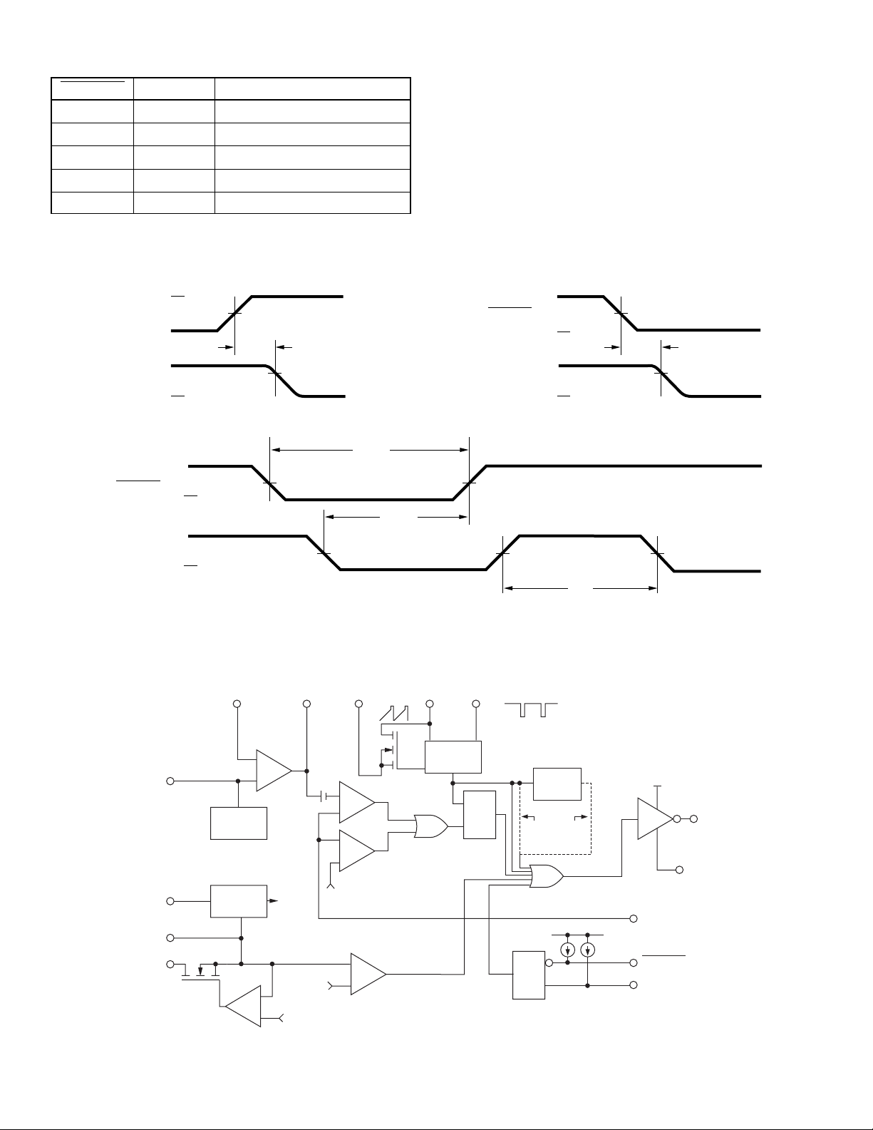
Truth Table
Shutdown Reset Output
H H Normal Operation
HH → L Normal Operation, No Change
L H Off, Not Latched
L L Off, Latched
L → H L Off, Latched, No Change
Shutdown Timing Waveforms
1.5V
Sense
Output
V
DD
50%
0
t
0
t
≤ 10ns
R
d
Shutdown
Output
HV9120/HV9123
t
V
DD
50%
0
t
SD
V
DD
0
90%90%
≤ 10ns
F
V
DD
Shutdown
Reset
0
V
DD
0
50%
Functional Block Diagram
COMP Discharge
14 (18) 10 (12) 9 (11) 8 (10)
Error
Amplifier
–
+
4V
–
+
To
Internal
Circuits
8.6V
2V
8.1V
+V
V
REF
BIAS
V
DD
IN
15 (19)
11 (14)
16 (20)
7 (9)
1 (3)
Pre-regulator/Startup
FB
REF
GEN
Current
Sources
1.2V
50%
–
+
+
–
t
SW
–
+
t
LW
OSC
In
Modulator
Comparator
Current Limit
Comparator
Undervoltage
Comparator
OSC
OSC
Out
R
S
50%
Q
50%
TQ
9123
S
Q
R
t
9120
V
DD
RW
50%
4 (5)
12 (16)
13 (17)
To V
DD
6 (8)
Sense
Shutdown
Reset
5 (6)
-
V
t
R
Output
IN
, tF ≤ 10ns
Pin number in parentheses are for PLCC package.
4
Page 5
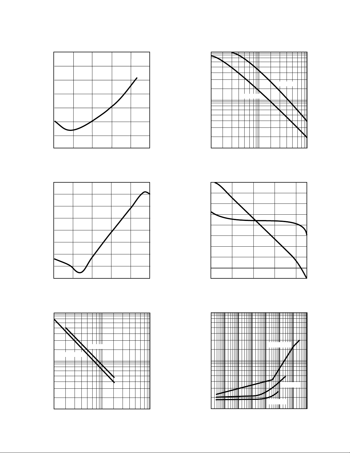
Typical Performance Curves
HV9120/HV9123
Fig. 1
Fig. 2
Error Amplifier Output Impedance (Z0)
6
10
5
10
4
10
3
10
(Ω)
O
Z
2
10
10
1
.1
100 1K 10K 100K 1M
Frequency (Hz)
PSRR — Error Amplifier and Reference
0
-10
-20
-30
-40
PSSR (dB)
-50
-60
-70
10M
Fig. 4
OUT
f (Hz)
Fig. 5
1M
100k
10k
10k
80
70
60
50
40
30
Gain (dB)
20
10
0
Output Switching Frequency
vs. Oscillator Resistance
HV9123
HV9120
100 k
R
(Ω)
OSC
Error Amplifier
Open Loop Gain/Phase
1M
180
120
-60
-120
-180
60
0
Phase (°C)
Fig. 3
Bias Current (µA)
-80
100
10
1M10K100 100K1K110
Frequency (Hz)
Fig. 6
VDD = 12V
VDD = 10V
-10
100 1K 10K
Frequency (Hz)
R
4
10
3
10
DISCHARGE
vs. t
100K 1M
(9123 only)
OFF
R
= 100K
OSC
(nsec)
OFF
t
R
= 10K
OSC
R
= 1K
2
1
5
10
6
10
7
10
Bias Resistance (Ω)
10
-1
0
10
10
1
10
10
R
DISCHARGE
OSC
2
3
4
5
10
10
10
6
10
(Ω)
5
Page 6
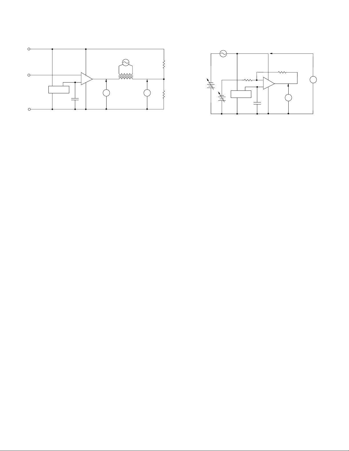
Test Circuits
+
–
Reference
V
1
V
2
0.1V swept 10Hz – 1MHz
0.1µF
10.0V
4.00V
100K1%
100K1%
PSRR
HV9120/HV9123
+10V
)
(V
DD
(FB)
GND
(–V
)
IN
NOTE: Set Feedback Voltage so that
V
Detailed Description
Preregulator
The preregulator/startup circuit for the HV912x consists of a highvoltage n-channel depletion-mode DMOS transistor driven by an
error amplifier to form a variable current path between the V
terminal and the VDD terminal. Maximum current (about 20 mA)
occurs when V
shuts off altogether when V
and 9.4V, so that if V
(generally the supply the chip is controlling) no current other than
leakage is drawn through the high voltage transistor. This minimizes dissipation.
An external capacitor between VDD and VSS is generally required
to store energy used by the chip in the time between shutoff of the
high voltage path and the VDD supply’s output rising enough to
take over powering the chip. This capacitor should have a value
of 100X or more the
being driven, i.e.,
C
≥ 100 x (gate charge of FET at 10V ÷ 10V)
storage
as well as very good high frequency characteristics. Stacked
polyester or ceramic caps work well. Electrolytic capacitors are
generally not suitable.
A common resistor divider string is used to monitor VDD for both
the undervoltage lockout circuit and the shutoff circuit of the high
voltage FET. Setting the undervoltage sense point about 0.6V
lower on the string than the FET shutoff point guarantees that the
undervoltage lockout always releases before the FET shuts off.
Bias Circuit
An external bias resistor, connected between the bias pin and V
is required by the HV912x to set currents in a series of current
mirrors used by the analog sections of the chip. Nominal external
bias current requirement is 15 to 20µA, which can be set by a
390KΩ to 510KΩ resistor if a 10V V
680KΩ resistor if V
required; ± 5% is fine.
Clock Oscillator
The clock oscillator of the HV912x consists of a ring of CMOS
inverters, timing capacitors, a capacitor discharge FET, and, in
Error Amp Z
–
+
Reference
0.1µF
= V
COMP
= 0, with current reducing as VDD rises. This path
DD
± 1mV before connecting transformer
DIVIDE
rises to somewhere between 7.8
DD
is held at 10 or 12V by an external source
DD
effective
gate capacitance of the MOSFET
OUT
1.0V swept 100Hz – 2.2MHz
Tektronix
P6021
(1 turn
V
1
secondary)
is used, or a 510kΩ to
DD
will be 12V. A precision resistor is
DD
V
2
60.4K
40.2K
SS
not
the 50% maximum duty cycle versions, a frequency dividing flipflop. A single external resistor between the OSC In and OSC Out
IN
pins is required to set oscillator frequency (see graph). For the
50% maximum duty cycle versions the Discharge pin is internally
connected to V
Discharge can either be connected to V
through a resistor used to set a deadtime.
V
SS
(ground). For the 99% duty cycle version,
SS
directly or connected to
SS
One difference exists between the Supertex HV912x and competitive 912x’s: The oscillator is shut off when a shutoff command is
received. This saves about 150µA of quiescent current, which
aids in the construction of power supplies to meet CCITT specification I-430, and in other situations where an absolute minimum
of quiescent power dissipation is required.
Reference
The Reference of the HV912x consists of a stable bandgap
reference followed by a buffer amplifier which scales the voltage
up to approximately 4.0V. The scaling resistors of the reference
buffer amplifier are trimmed during manufacture so that the output
of the error amplifier when connected in a gain of –1 configuration
is as close to 4.000V as possible. This nulls out any input offset
of the error amplifier. As a consequence, even though the observed reference voltage of a specific part may not be exactly
4.0V, the feedback voltage required for proper regulation will be.
A ≈50KΩ resistor is placed internally between the output of the
reference buffer amplifier and the circuitry it feeds (reference
output pin and non-inverting input to the error amplifier). This
allows overriding the internal reference with a low-impedance
voltage source ≤6.0V. Using an external reference reinstates the
input offset voltage of the error amplifier, and its effect of the exact
value of feedback voltage required. In general, because the
reference voltage of the Supertex HV912x is not noisy, as some
previous examples have been, overriding the reference should
seldom be necessary.
Because the reference of the 912x is a high impedance node, and
usually there will be significant electrical noise near it, a bypass
capacitor between the reference pin and V
mended. The reference buffer amplifier is intentionally compensated to be stable with a capacitive load of 0.01 to 0.1µF.
6
is strongly recom-
SS
Page 7
Detailed Description (continued)
HV9120/HV9123
Error Amplifier
The error amplifier in the HV912x is a true low-power differential
input operational amplifier intended for around-the-amplifier compensation. It is of mixed CMOS-bipolar construction: A PMOS
input stage is used so the common-mode range includes ground
and the input impedance is very high. This is followed by bipolar
gain stages which provide high gain without the electrical noise of
all-MOS amplifiers. The amplifier is unity-gain stable.
Current Sense Comparators
The HV912x uses a true dual comparator system with independent comparators for modulation and current limiting. This allows
the designer greater latitude in compensation design, as there are
no clamps (except ESD protection) on the compensation pin. Like
the error amplifier, the comparators are of low-noise BiCMOS
construction.
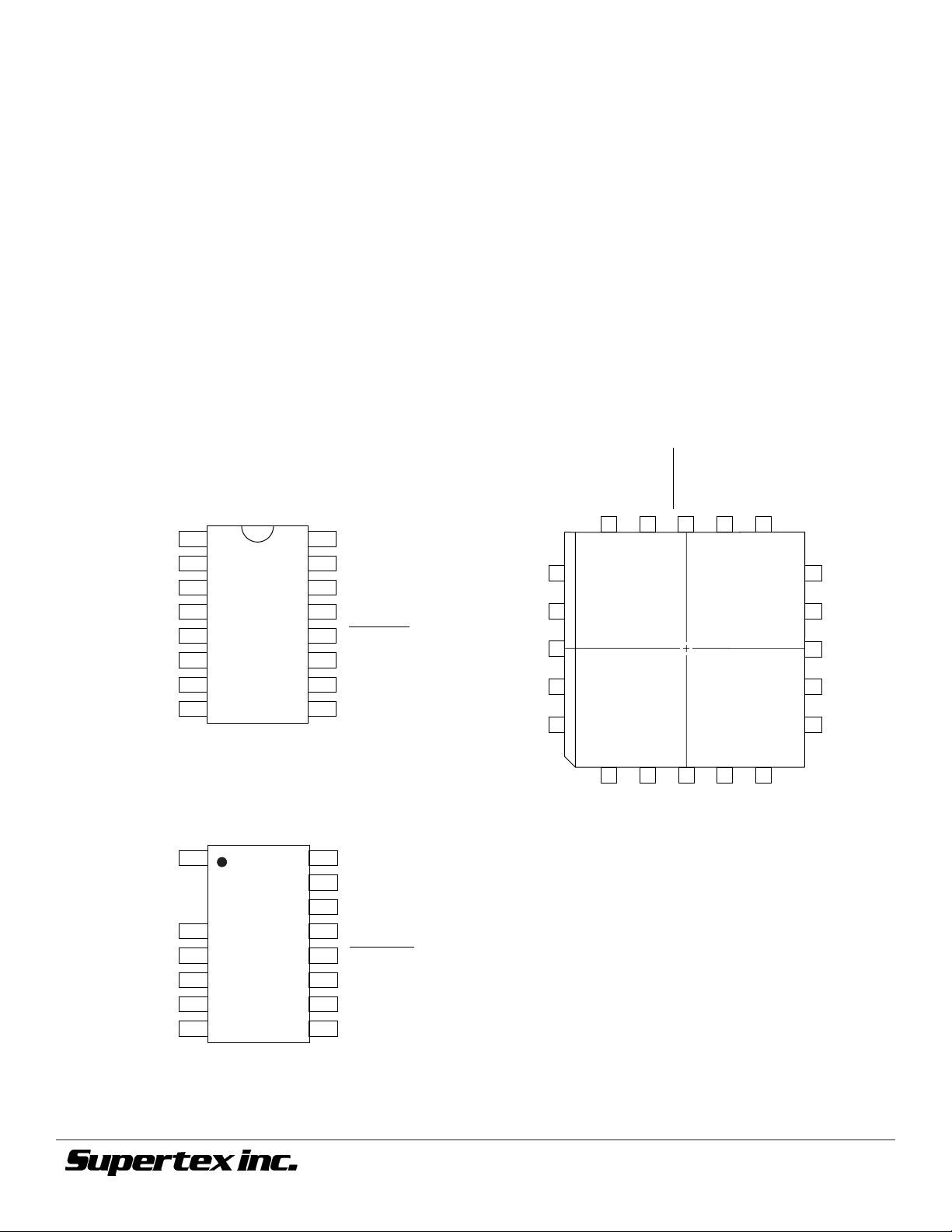
Pinout
+V
NC
NC
Sense
Output
–V
V
DD
OSC Out
1
IN
2
3
4
5
6
IN
7
8
16 Pin Dip Package
top view
16
15
14
13
12
11
10
9
BIAS
FB
COMP
Reset
Shutdown
V
REF
Discharge
OSC In
Remote Shutdown
The shutdown and reset pins of the HV912x can be used to
perform either latching or non-latching shutdown of a converter as
required. These pins have internal current source pull-ups so they
can be driven from open-drain logic. When not used they should
be left open, or connected to V
DD
.
Output Buffer
The output buffer of the HV912x is of standard CMOS construction (P-channel pull-up, N-channel pull-down). Thus the bodydrain diodes of the output stage can be used for spike clipping if
necessary, and external Schottky diode clamping of the output is
not required.
NC
7 8
NC
V
–V
REF
IN
13
NC
12
Discharge
11
OSC In
10
OSC Out
V
9
DD
FB
BIAS
NC
NC
+V
COMP
Reset
Shutdown
18 17 16
19
20
1
•
2
3
IN
4 5 6
15 14
NC
Sense
Output
+V
Sense
Output
–V
V
OSC Out
DD
1
IN
4
5
6
IN
7
8
16
15
14
13
12
11
10
9
BIAS
FB
COMP
Reset
Shutdown
V
REF
Discharge
OSC In
16 Pin SOIC
top view
Note: Pins 2 and 3 are removed
©2001 Supertex Inc. All rights reserved. Unauthorized use or reproduction prohibited.
20-pin PJ Package
top view
11/12/01
1235 Bordeaux Drive, Sunnyvale, CA 94089
TEL: (408) 744-0100 • FAX: (408) 222-4895
7
www.supertex.com
 Loading...