

Page 1
10-Channel Serial-Input Latched Display Driver
Ordering Information
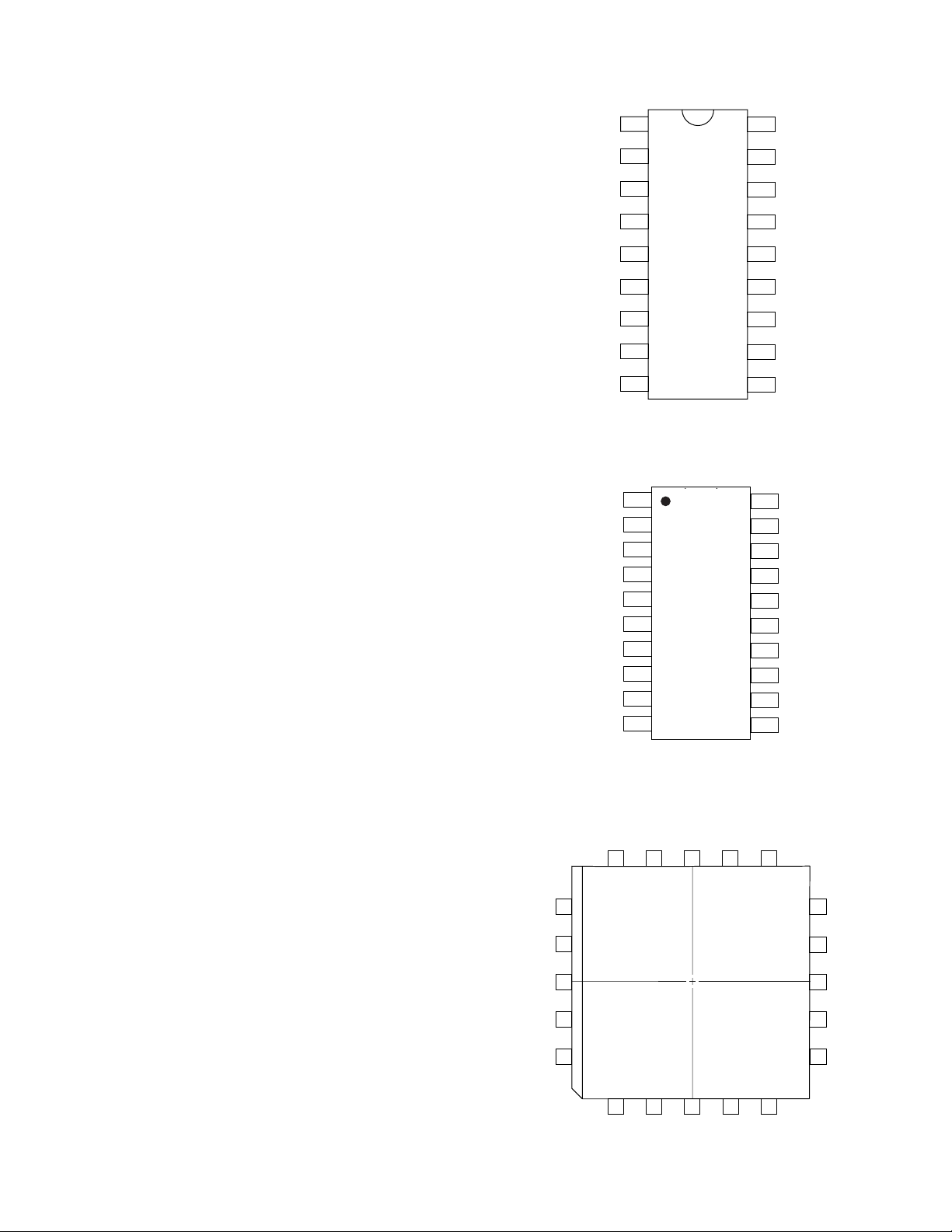
Package Options
Device 18-Pin 20-Pin Small 20-Pin Plastic Die
Plastic DIP Outline Package Chip Carrier
HV6810 HV6810P HV6810WG HV6810PJ HV6810X
*For Hi-Rel process flow, refer to page 5-3 of the Databook.
HV6810
Features
■■ High output voltage 80V
■■ High speed 5MHz @ 5V
■■ Low power IBB ≤ 0.1mA (All high)
■■ Active pull down 100µA min
■■ Output source current 100mA at 60V V
■■ Each device drives 10 lines
■■ High-speed serially-shifted data input
■■ 5V CMOS-compatible inputs
■■ Latches on all driver outputs
■■ Pin-compatible improved replacement for UCN5810A
and TL4810A, TL4810B
Absolute Maximum Ratings
Logic supply voltage, V
Driver supply voltage, V
Output voltage
Input voltage
Continuous total power dissipation 18-Pin P-DIP
at 25°C free-air temperature
Operating Temperature Range -40° to +85*C
Notes:
1. Over operating free-air temperature.
2. All voltages are referenced to V
3. For operation above 25°C ambient derate linearly to 85°C at 15mW/°C.
4. For operation above 25°C ambient derate linearly to 85°C at 16.7mW/°C.
2
2
DD
BB
DD
PP
1
2
2
-0.3V to VDD + 0.3V
3
.
SS
20-Pin SOIC41000mW
20-Pin PLCC41000mW
3
7.5V
90V
90V
900mW
General Description
The HV6810 is a monolithic integrated circuit designed to drive a
dot matrix or segmented vacuum fluorescent display (VFD).
These devices feature a serial data output to cascade additional
devices for large displays.
A 10-bit data word is serially loaded into the shift register on the
positive-going transition of the clock. Parallel data is transferred
to the output buffers through a 10-bit D-type latch while the latch
enable input is high and is latched when the latch enable is low.
When the blanking input is high, all outputs are low.
Outputs are structures formed by double-diffused MOS (DMOS)
transistors with output voltage ratings of 80 volts and 25 milliampere source-current capability. All inputs are compatible with
CMOS levels.
12-142
Page 2
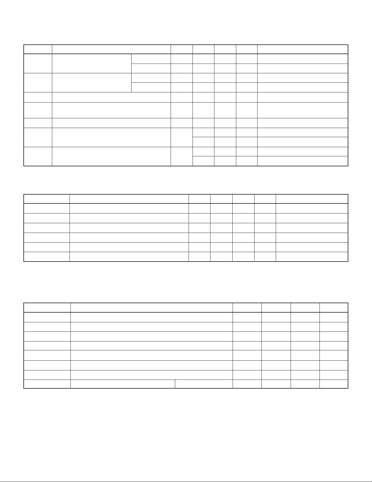
Electrical Characteristics
DC Characteristics (V
Symbol Parameter Min Typ Max Units Conditions
V
OH
V
OL
I
OL
I
O(OFF)
I
H
I
DD
I
BB
*
All typical values are at TA = 25°C, except for IO.
High-level output voltage Q outputs 57.5 58 V IOH = 25mA
Low-level output voltage Q outputs 0.15 1 V IOH = 100µA, Blanking input at V
Low-level Q output current (pull-down current) 60 80 µATA = Max, VOL = 0.7V
Off-state output current -1 -15 µAVO = 0, Blanking input
High-level input current 1 µAVI = V
Supply current from VDD (standby) 10 50 µA All inputs at 0V, one Q output high
Supply current from V
AC Characteristics (Timing requirements over recommended operating conditions)
Symbol Parameter Min Typ Max Units Conditions
t
W(CKH)
t
W(LEH)
t
SU(D)
t
H(D)
t
CKH-LEH
* Propagation delay time, latch enable to output 0.3 µs
t
pd
Switching characteristics, VBB = 60V, TA = 25°C.
*
Pulse duration, clock high 100 ns
Pulse duration, latch enable high 100 ns
Setup time, data before clock 50 ns
Hold time, data after clock 50 ns
Delay time, clock to latch enable high 50 ns
= 5V ±10%, VBB = 60V, VSS = 0, TA = 25°C unless otherwise noted)
DD
Serial output 4 4.5 V V
DD
Serial output 0.05 0.1 V VDD = 4.5V, IOL = 100µA
T
A
10 50 µA All inputs at 0V, all Q outputs low
BB
0.05 0.1 mA All outputs low, all Q outputs open
0.05 0.1 mA All outputs high, all Q outputs open
= 4.5V, IOH = -100µA
= Max at V
DD
DD
HV6810
DD
Recommended Operating Conditions
Symbol Parameter Min Nom Max Units
V
DD
V
BB
V
SS
V
IH
V
IL
I
OH
f
CLK
T
A
Note:
Power-up sequence should be the following:
1. Connect ground.
2. Apply V
3. Set all inputs (Data, CLK, Enable, etc.) to a known state.
4. Apply V
Power-down sequence should be the reverse of the above.
DD
PP
.
.
Supply voltage 4.5 5.5 V
Supply voltage 20 80 V
Supply voltage 0 V
High-level input voltage (for VDD = 5V) 3.5 5.3 V
Low-level input voltage -0.3 0.8 V
Continuous high-level Q output current -25 mA
Clock frequency 5 MHz
Operating free-air temperature Plastic -40 +85 °C
12-143
Page 3
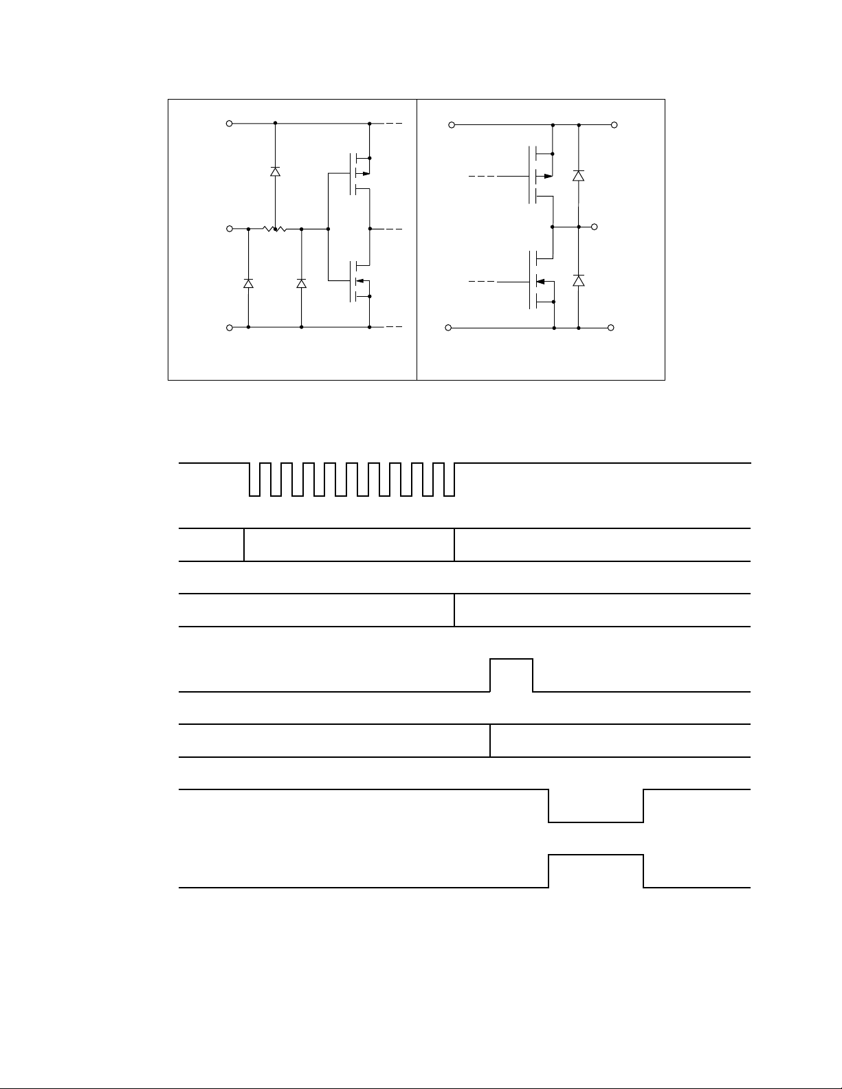
Input and Output Equivalent Circuits
HV6810
V
DD
Input
V
SS
Timing Diagram
Clock
Input Equivalent Circuit
Logic Data Output
V
Output
V
BB
SS
Data In
SR Contents
Latch
Enable
Latch
Contents
Blanking
Q Outputs
VALID IRRELEVANT
INVALID VALID
PREVIOUSLY STORED DATA NEW DATA VALID
VALID
12-144
Page 4
w(CKH)
t
50%
50%
V
IH
V
IL
V
IH
V
Valid
50% 50%
Data
Clock
h(D)
t
su(D)
t
50%
V
IH
V
IL
V
IH
V
IL
50% 50%
CKH–LEH
t
Valid
Valid
90%
Clock
Input
Latch
Enable
Output
pd
t
w(LEH)
t
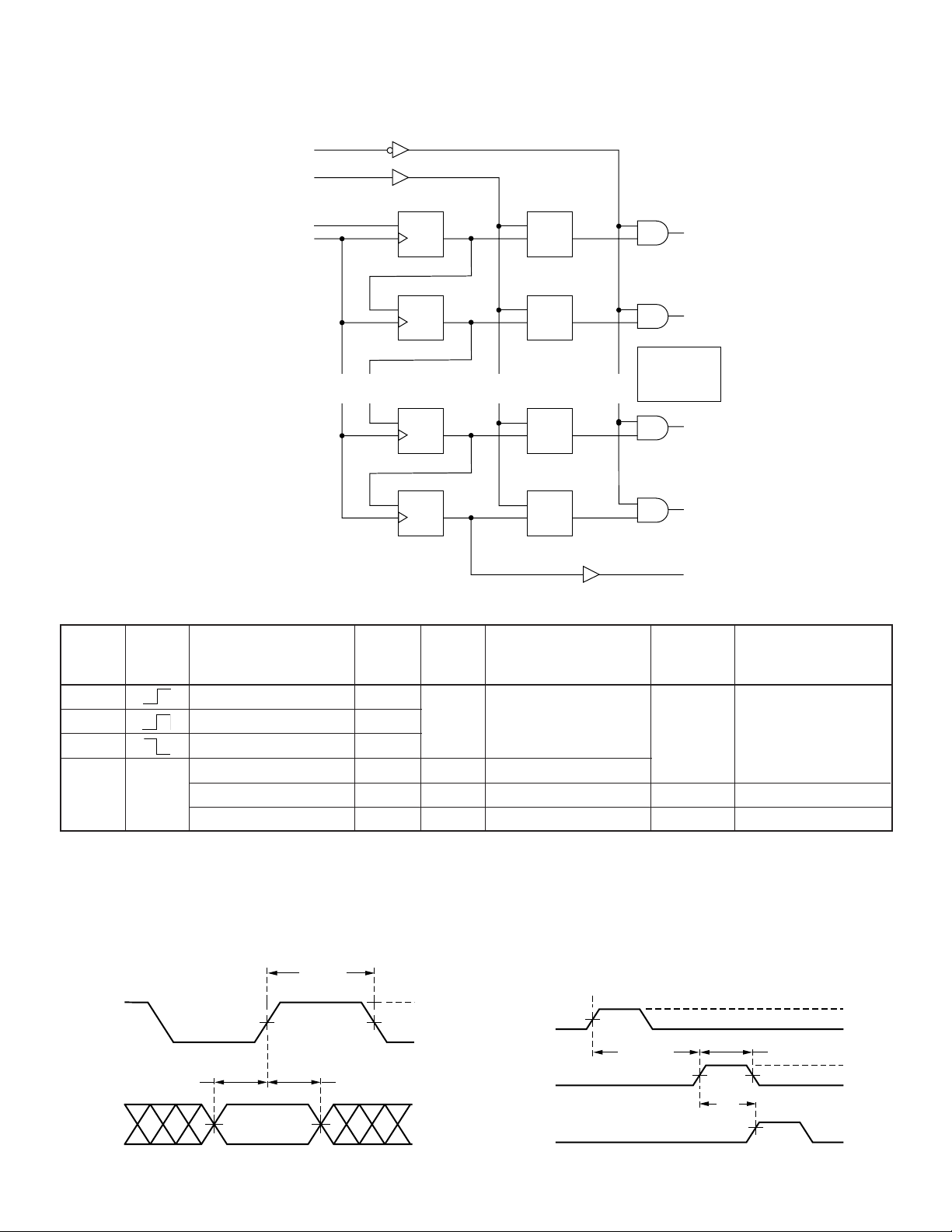
Functional Block Diagram
Blanking
Latch Enable
Data Input
Clock
Logic Diagram (positive logic)
LatchesShift Register
1D
C1
R1
C2
2D
LC1
HV6810
Q1
1D
C1
R2
C2
2D
LC2
Q2
6 Stages
•
•
•
•
•
•
1D
C1
1D
C1
R9
R10
•
•
•
C2
LC9
2D
C2
LC10
2D
(Q3 thru Q8)
•
•
not shown
•
Q9
Q10
Serial
Out
Function Table
Serial Shift Register Contents Serial Latch Contents Output Contents
Data Data
Input I
HHR
LLR
XR
L = Low logic level
H = High logic level
X = Irrelevant
P = Present state
R = Previous state
Clock Strobe Blanking
Input Input Input
1I2I3
XXX…X X X L R1R2R3…R
P1P2P3…P
1R2
1R2
1R2R3
…I
…R
…R
…R
N-1IN
N-2RN-1
N-2RN-1
N-1RN
N-1PN
Output I1I2I3…I
R
N-1
R
N-1
R
N
P
N
H
P1P2P3…P
N-1IN
N-1RN
N-1PN
L
XXX…X X H LLL…L L
I1I2I3…I
P1P2P3…P
N-1IN
N-1PN
Switching Waveforms
Input Timing Output Switching Times
12-145
Page 5
HV6810
1
2
3
4
5
6
7
8
9
18
17
16
15
14
13
12
11
10
top view
18-pin DIP
Pin Configurations
HV6810
18-Pin DIP
Pin Function Pin Function
1Q8 10Q3
2Q7 11Q2
3Q6 12Q1
4 Clock 13 Blanking
5V
SS
6V
DD
7 LE (strobe) 16 Serial data out
8 Q5 17 Q10
9Q4 18Q9
HV6810
20-Pin SOW
Pin Function Pin Function
1Q8 11Q3
2Q7 12Q2
3Q6 13Q1
4 Clock 14 Blanking
5V
SS
6 N/C 16 V
7V
DD
8 LE (strobe) 18 N/C
9 Q5 19 Q10
10 Q4 20 Q9
14 Data in
15 V
BB
15 Data in
BB
17 Serial data out
Package Outlines
1
2
3
4
5
6
7
8
9
10
20
19
18
17
16
15
14
13
12
11
HV6810
20-Pin Plastic PLCC
Pin Function Pin Function
1Q8 11Q3
2Q7 12Q2
3Q6 13Q1
4 Clock 14 Blanking
SS
DD
16 N/C
17 V
BB
5 N/C 15 Data In
6V
7V
8 LE(Strobe) 18 Serial data out
9 Q5 19 Q10
10 Q4 20 Q9
12-146
top view
SOW-20
18 17 16
19
20
1
•
2
3
4 5 6
15 14
13
12
11
10
9
7 8
top view
20-pin PLCC
 Loading...