

Page 1
275V 40-Channel Row Driver with SCR Outputs
Ordering Information
HV506
Preliminary
Package Options
Device
80-Lead 64-Lead 3-Sided
Ceramic Gullwing Plastic Gullwing Die
HV506 HV506DG HV506PG HV506X
Features
❏ Processed with HVDI technology
❏ Symmetric row drive
❏ Output voltage up to 275V
❏ Source/Sink current 300mA (min.)
❏ Shift Register Speed 3MHz
❏ Pin-programmable shift direction (DIR)
❏ Hi-Rel processing available
General Description
The HV506 is a low-voltage serial to high-voltage parallel converter with push-pull outputs. It is especially suitable for use as
a symmetric row driver in AC thin-film electroluminescent
(ACTFEL) displays.
When the data reset pin (DR
outputs of the internal shift register to zero. At the same time, the
output of the shift register will start shifting a logic high from the
least significant bit to the most significant bit. The DR
triggered at any time. The DIR pin controls the direction of data
through the device. When DIR is at logic high, DR
and DR
and the DR
Table for output sequence. The POL and OE pins perform the
is the output. When DIR is grounded, DR
IOB
is the output. See the Output Sequence Operation
IOA
polarity select and output enable function respectively. Data is
clocked through the shift register loaded on the low to high
Absolute Maximum Ratings
Logic supply voltage, LV
Output supply voltage, V
Substrate bias voltage, V
Output voltage, HV
OUT
Logic input levels -0.5V to VDD +0.5V
Continuous total power dissipation
Operating temperature range Plastic -40°C to +85°C
DD
DD
sub
1
1
-0.5V to +15V
-0.5V to +15V
See Note 3
±300V
2
Ceramic 1900mW
Plastic 1200mW
transition of the clock. A logic high in the shift register will cause
the other corresponding output to swing to V
to V
if POL is low. All other outputs will be in the High-Z state.
SS
If OE is at logic high all outputs will be in the High-Z state. An
output in the High-Z state may block up to 275V above V
275V below VDD. The DP/DN pins are for the positive/negative
discharge of the high voltage output HV
are provided for cascading devices.
LVDD requires low current for the HV506 logic section. V
requires high current for the output section . Typically these two
pins are at the same potential. The same current and potential
conditions apply to the LVSS, logic, and VSS, output pins. V
always be equal or greater than the most positive supply.
Ceramic -55°C to +125°C
Storage temperature range -65°C to +150°C
Lead temperature 1.6mm (1/16 inch) 260°C
from case for 10 seconds
Notes:
1. All voltages are referenced to V
2. For operation above 25°C ambient derate linearly to maximum operating
temperture at 20mW/°C for plasitc and at 19mW/°C for ceramic.
3. V
must be the most positive with respect to VSS.
sub
.
SS
) is at logic high, it will reset all the
IO
can be
IO
is the input
IOA
is the input
IOB
if POL is high, or
DD
. Data output buffers
OUT
must
sub
or
SS
DD
12/13/01
Supertex Inc. does not recommend the use of its products in life support applications and will not knowingly sell its products for use in such applications unless it receives an adequate "products liability
indemnification insurance agreement." Supertex does not assume responsibility for use of devices described and limits its liability to the replacement of devices determined to be defective due to
workmanship. No responsibility is assumed for possible omissions or inaccuracies. Circuitry and specifications are subject to change without notice. For the latest product specifications, refer to the
Supertex website: http://www.supertex.com. For complete liability information on all Supertex products, refer to the most current databook or to the Legal/Disclaimer page on the Supertex website.
1
Page 2
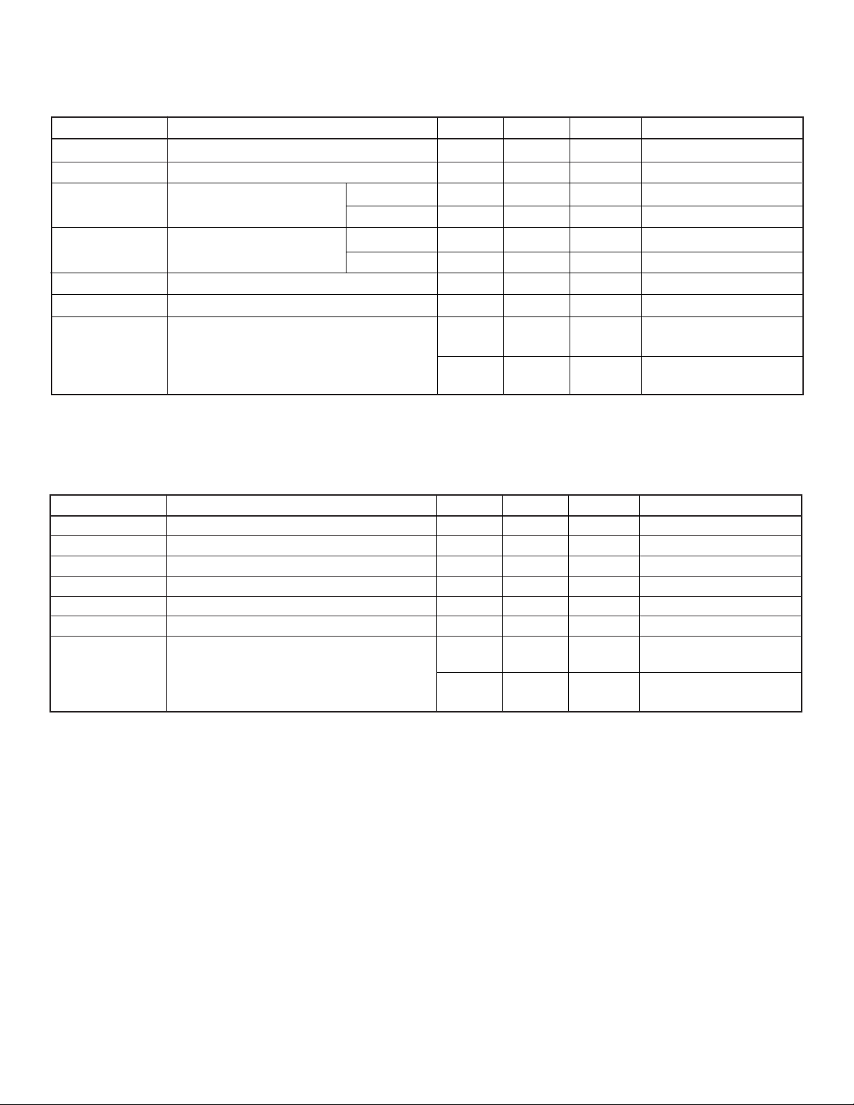
Electrical Characteristics
(over recommended operating conditions of V
DC Characteristics
Symbol Parameter Min Max Units Conditions
I
DD
I
DDQ
V
OH
V
OL
I
IH
I
IL
I
OFF
Notes:
1. Only one output can be turned on at a time.
VDD supply current 10 mA f
Quiescent VDD supply current 100 µA All VIN = V
High-level output HV
Low-level output HV
High-level logic input current 1 µAV
Low-level logic input current -1 µAV
Output OFF leakage current (High-Z) 10 µAHV
= 12V, LVDD = 12V, and TA = 25°C unless noted)
DD
OUT
VDD-10 V IO= -300mA
Data out 10.8 V IO= -100µA
OUT
VSS+10 V IO= 300mA
Data out 1.2 V I
10 µAVDD - HV
= 3MHz
CLK
= 100µA
O
= V
IH
= V
IL
OUT
V
= HV
sub
V
= V
sub
or V
SS
DD
DD
SS
- VSS = 275V,
OUT
= 275V,
OUT
DD
SCR Characteristics
Symbol Parameter Min Max Units Conditions
V
V
I
OH
OL
I
V
I
H
V
OFF
L
L
H
High-level output VDD-10 V IO= -300mA
Low-level output VSS+10 V IO= 300mA
Latching Current 15 mA
Latching Voltage 100 V
Holding Current 10 mA
Holding Voltage 10 V
Output OFF leakage current (High-Z) 10 µAHV
10 µAVDD - HV
OUT
= HV
V
sub
= V
V
sub
- VSS = 275V,
OUT
= 275V,
OUT
DD
2
Page 3
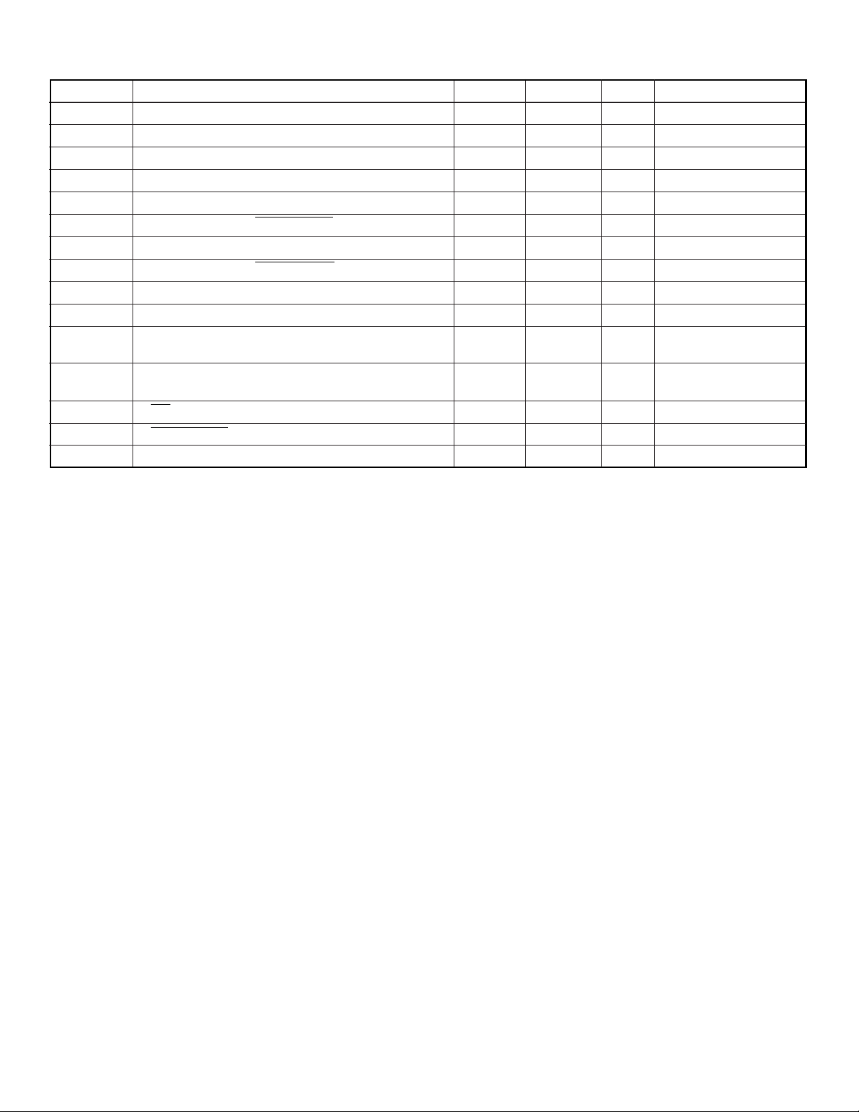
AC Characteristics
Symbol Parameter Min Max Units Conditions
f
CLK
t
W (H/L)
t
SUD
t
HD
t
SUC
t
SUE
t
HC
t
HE
*
t
DHL
*
t
DLH
t
OFF(SCR)
t
OFF(D)
t
POW
t
OEW
SR Slew rate of HV
Clock frequency 3 MHz
Pulse width - clock high or low 150 ns
Data set-up time before clock rises 50 ns
Data hold time after clock rises 50 ns
HV
delay from clock rises (Hi-Z to H or L) 1 µsCL = 10nF
OUT
HV
delay from Output Enable rises 600 ns CL = 10nF
OUT
HV
delay from clock rises (H or L to Hi-Z) 2 µsCL = 10nF
OUT
HV
delay from Output Enable rises 600 ns CL = 10nF
OUT
Delay time clock to data output falls 250 ns CL = 15pF
Delay time clock to data output rises 250 ns CL = 15pF
Turn off time of output SCR 4 µs Time after I
= 10nF
C
L
Turn off time of output diode 2 µs Time after I
CL = 10nF
POL pulse width 3 µs
Output Enable pulse width 3 µs
OUT
200 V/µs
OUT
OUT
HV506
≤ 2mA,
≤ 2mA,
* The delay is measured from the trailing edge of the clock but the data is triggered by the rising edge of the clock. There is an internal delay for the data output which is
equal to t
. Therefore the delay is measured from the trailing edge of the clock.
WH
3
Page 4
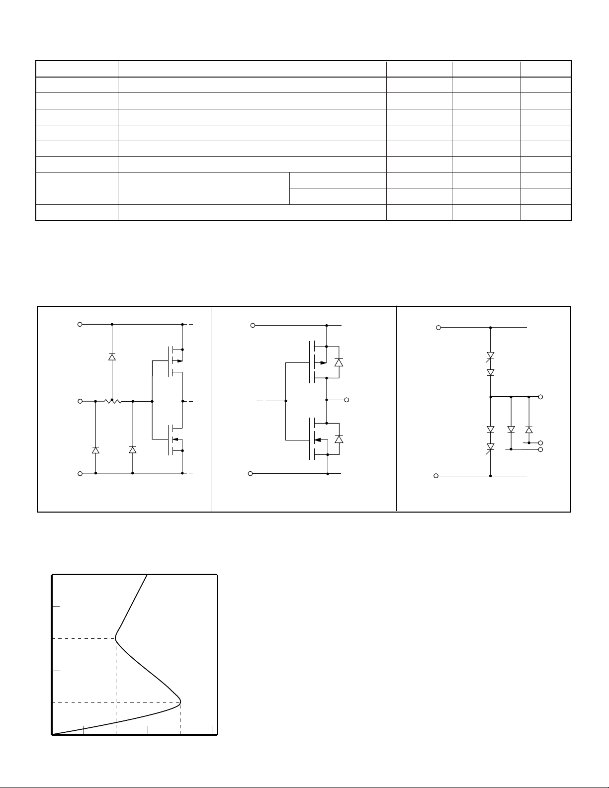
Recommended Operating Conditions
Symbol Parameter Min Max Units
LV
V
f
V
V
CLK
I
T
DD
DD
IH
IL
O
A
Logic supply voltage 10.8 13.2 V
Output supply voltage 10.8 13.2 V
High-level input voltage 0.8LV
DD
Low-level input voltage 0 0.2LV
LV
DD
DD
Clock frequency 3 MHz
High voltage output current ±300 mA
Operating free-air temperature Plastic -40 +85 °C
Ceramic -55 +125 °C
I
OD
Notes:
The substrate pin V
LV
are measured with respect to LVSS/VSS.
DD/VDD
sub
Allowable pulse current through diodes ±500 mA
(pin 39) must be biased for proper output breakdown voltage. V
≥ VDD or HV
sub
whichever is higher.
OUT
Input and Output Equivalent Circuits
HV506
V
V
LV
DD
Input
LV
SS
Logic Inputs
SCR Characteristics
I
LV
LV
DD
SS
Logic Data Output
Data Out
V
DD
HV
OUT
D
N
D
P
V
SS
High Voltage Outputs
I
H
I
L
V
H
V
L
V
4
Page 5
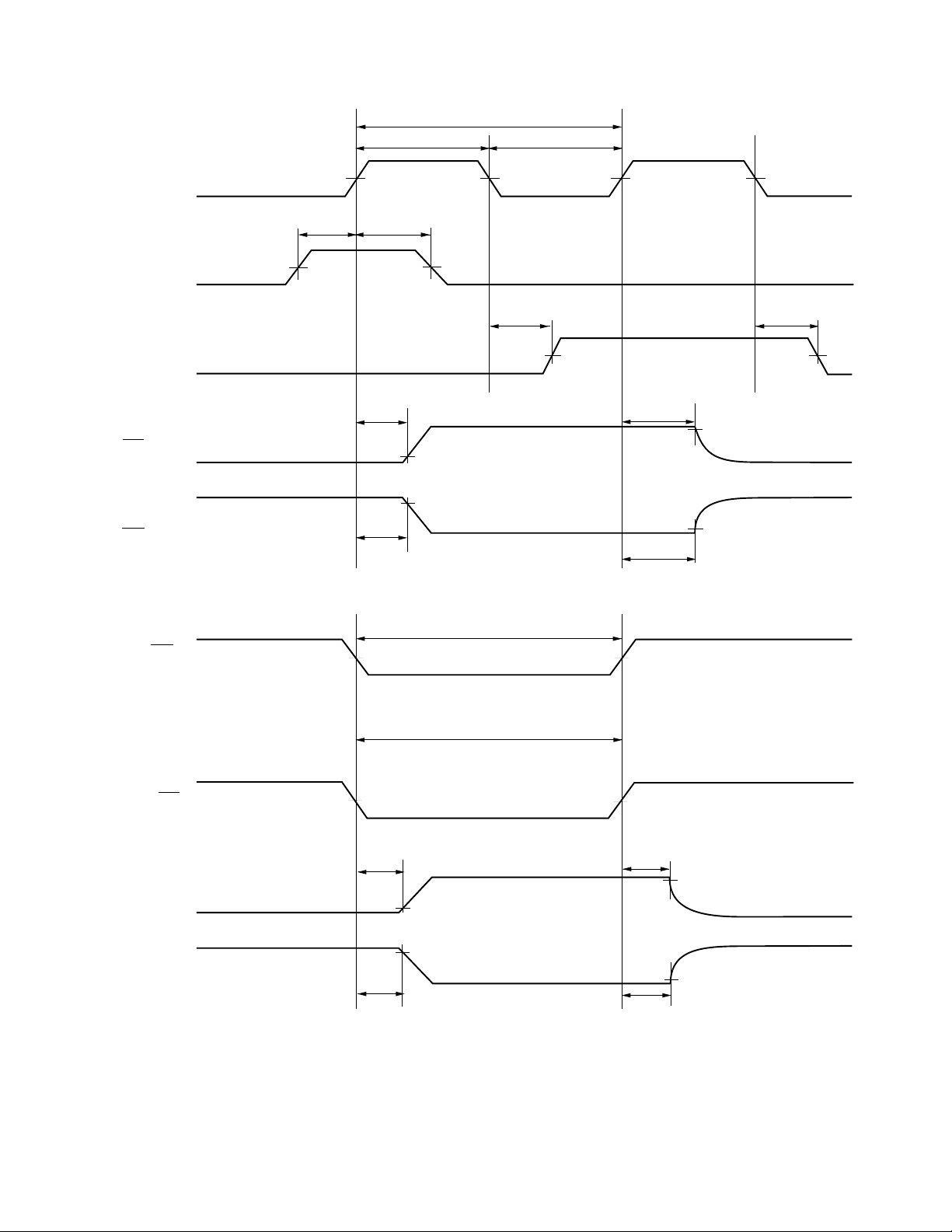
Switching Waveforms
CLK
Data Reset Input
(DR
/DR
/DR
IOB
IOB
)
)
IOA
Data Reset Output
(DR
IOA
t
SUD
50%
1/f
CLK
t
DLH
t
WL
50%
t
DHL
50%
50%
t
WH
50% 50% 50%
t
HD
Data
Valid
50%
HV506
V
IH
V
IL
V
IH
V
IL
V
OH
V
OL
HV
OUT
(POL = H)
HV
OUT
(POL = L)
POL
OE
HV
OUT
HV
OUT
t
SUC
t
SUC
50%
50%
t
SUE
t
SUE
10%
90%
10%
90%
t
POW
t
OEW
50%
50%
t
HE
t
HE
t
HC
90%
V
OH
High ImpedanceHigh Impedance
10%
t
HC
90%
V
OL
V
IH
V
IL
V
IH
V
IL
V
OH
High ImpedanceHigh Impedance
10%
V
OL
5
Page 6
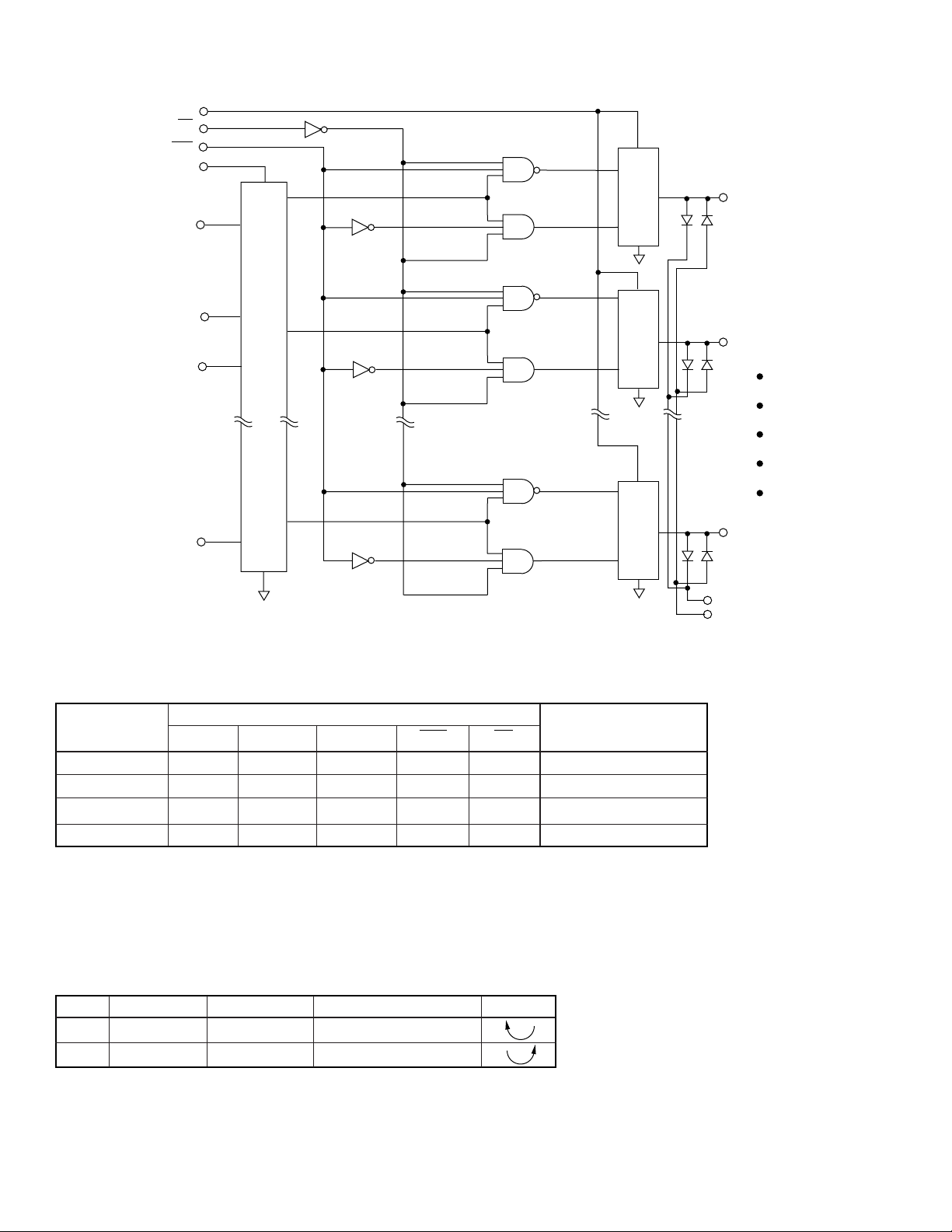
Functional Block Diagram
V
DD
OE
POL
LV
DD
DR
IOA
CLK
S/R
DIR
Output
Output
HV
HV
OUT
OUT
HV506
1
2
DR
IOB
LV
SS
Function Table
I/O Relations
CLK DIR S/R Data POL OE HV Outputs
O/P HIGH X X H H L H
O/P OFF X X L X L HIGH-Z
O/P LOW X X H L L L
O/P OFF X X X X H All O/P HIGH-Z
Note:
H = logic high level, L = logic low level, X = irrelevant
Inputs
Output Sequence Operation Table
DIR Data Reset In Data Reset Out HV
LDR
HDR
Notes:
1. DR
is DR
IOA
2. DR
is DR
IOB
3. Reference to chip layout drawing.
IOB
IOA
delayed by 40 clock pulses.
IOB
delayed by 40 clock pulses.
IOA
DR
DR
IOA
IOB
1
2
# Sequence Direction
OUT
40 → 1
1 → 40
3
Output
V
SS
HV
40
OUT
D
P
D
N
6
Page 7
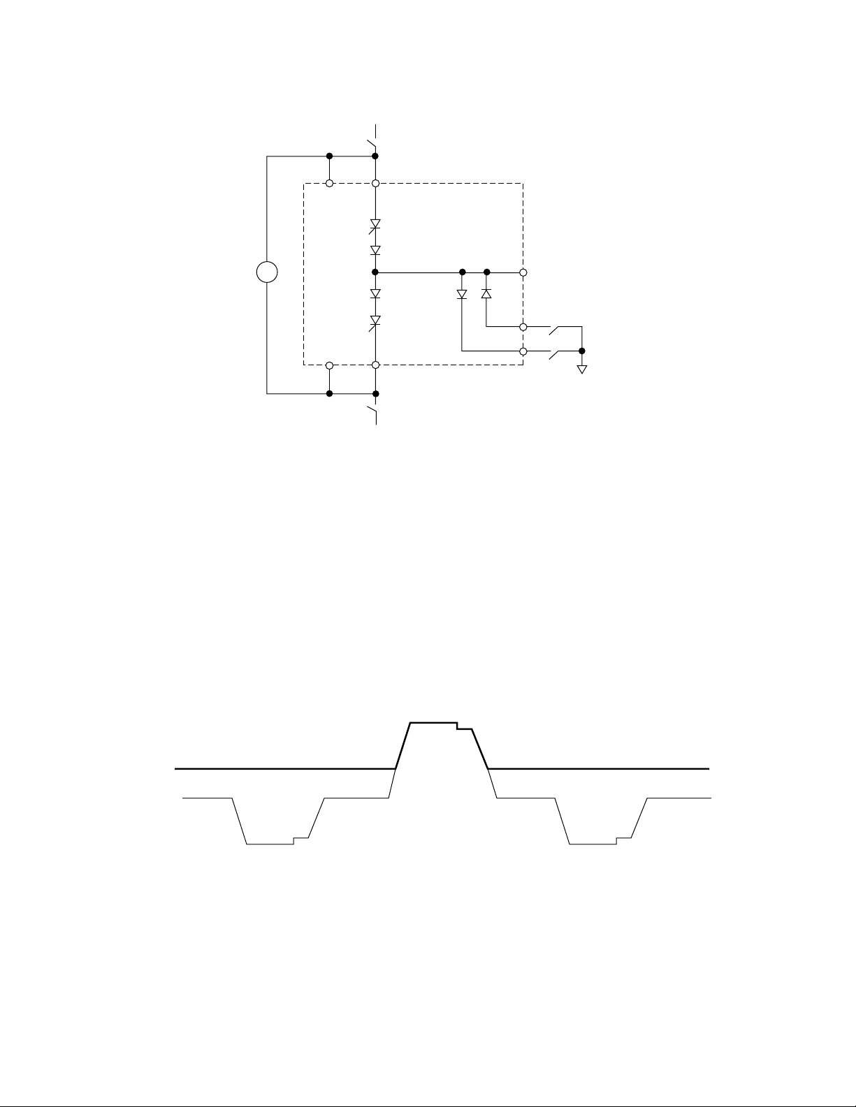
Typical Output Circuit Connections
+HV
V
DD
Source SCR
D
D
Sink SCR
V
SS
-HV
3
4
12V
LV
DD
+
–
LV
SS
HV506
HV506
HV
OUT
D
1
D
2
D
N
D
P
GND
Substrate Bias Operation
In order to achieve the desired output breakdown voltage, the
substrate must be biased to the most positive potential of any
circuit node. For this condition, V
V
sub
V
SS
sub
-HV
≥ VDD or HV
V
columns
0V
whichever is
OUT
+ HV
Note: The voltage potential between LVDD/VDD and LVSS/VSS must not exceed
recommended operating conditions of 10.8V - 13.2V (12V typical)
higher. Refer to Typical Output Circuit Connections for wiring. A
typical V
signal is shown below.
sub
Note: In general, when driving the outputs positive, V
outputs negative, V
equals most positive voltage; e.g. GND or >0V.
SUB
7
= +HV. And when driving
SUB
Page 8
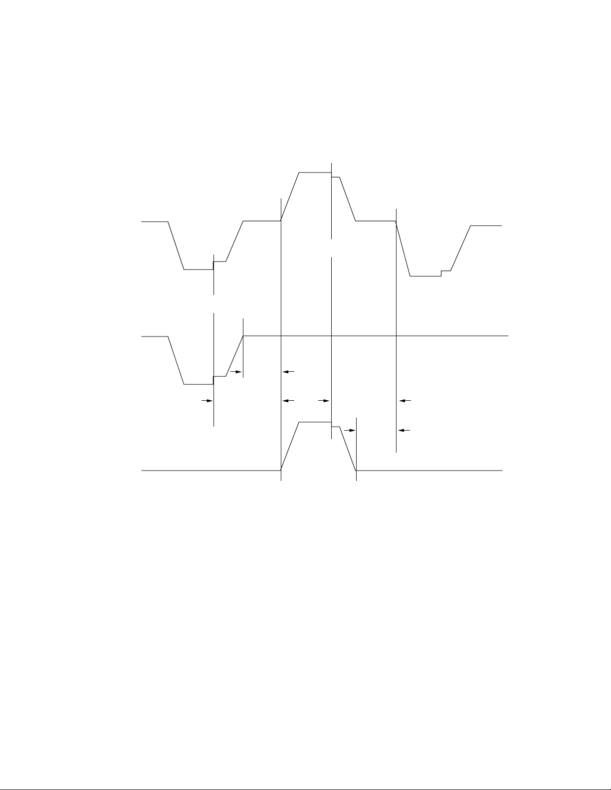
HV Switching Waveforms and Operation
HV506
To drive a TFEL row with a negative pulse: The desired sink SCR
is enabled and V
switch. After holding the output at the -HV level, the switch is
is connected to -HV via a current limited
SS
opened in order to set the sink SCR current to zero. The row is
+ HV - (VDD - VSS)
V
SS
Output n
- HV
Drive Current
Disabled
Sink*
SCR
0V
D
*
2
t
(D2)
OFF
then discharged through a discharge diode when D2 is switched
to GND. The application of a positive pulse to a row operates in
a similar manner using the selected source SCR and D
Drive Current
Disabled
High Impedance
.
1
t
t
(Sink SCR)
OFF
Output n+1
* Notes internal device handling current flow. Refer to Typical Output Circuit Connections for schematic.
High Impedance High Impedance
Source*
SCR
OFF
(Source SCR)
t
OFF
D
*
1
(D1)
8
Page 9
HV506
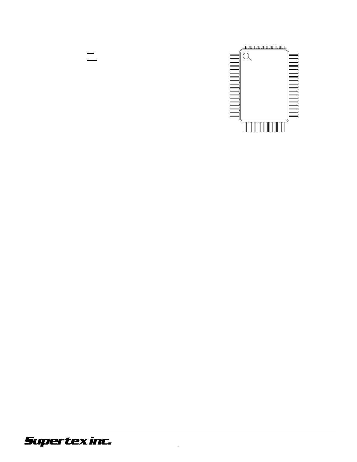
Pin Configurations
HV506
Option A:
Pin Function Pin Function
1HV
2HV
3HV
4HV
5HV
6HV
7HV
8HV
9HV
10 HV
11 HV
12 HV
13 HV
14 HV
15 HV
16 HV
17 HV
18 HV
19 HV
20 HV
21 N/C 53 HV
22 D
23 D
24 N/C 56 HV
25 N/C 57 HV
26 LV
27 V
28 DIR 60 HV
29 V
30 CLOCK 62 HV
31 DR
32 DR
Note: Pins 65–80 are NC.
133OE
OUT
234POL
OUT
335LV
OUT
436V
OUT
537V
OUT
638LV
OUT
739V
OUT
840N/C
OUT
941N/C
OUT
10 42 D
OUT
11 43 D
OUT
12 44 N/C
OUT
13 45 HV
OUT
14 46 HV
OUT
15 47 HV
OUT
16 48 HV
OUT
17 49 HV
OUT
18 50 HV
OUT
19 51 HV
OUT
20 52 HV
OUT
P
N
SS
DD
SS
IOA
IOB
54 HV
55 HV
58 HV
59 HV
61 HV
63 HV
64 HV
SS
DD
sub
N
P
DD
SS
OUT
OUT
OUT
OUT
OUT
OUT
OUT
OUT
OUT
OUT
OUT
OUT
OUT
OUT
OUT
OUT
OUT
OUT
OUT
OUT
21
22
23
24
25
26
27
28
29
30
31
32
33
34
35
36
37
38
39
40
Package Outline
1
Index
24
25
top view
3-sided Plastic 64-pin Gullwing Package
64
41
40
©2001 Supertex Inc. All rights reserved. Unauthorized use or reproduction prohibited.
12/13/010
1235 Bordeaux Drive, Sunnyvale, CA 94089
9
TEL: (408) 744-0100 • FAX: (408) 222-4895
www.supertex.com
 Loading...