

Page 1
Features
Single-chip CMOS construction
·
Single 1.5V battery operation
·
Measurement range: +32.0~+42.0°C
·
(+90.0~+108.0°F)
Measurement accuracy: ±0.1°C(±0.2°F)
Resolution: 0.1°C (0.1°F)
Bonding option for Centigrade/Fahrenheit
·
measurement
General Description
The HT7500 is a CMOS digital clinical ther
mometer IC for measuring body temperature in
Centigrade (°C) or Fahrenheit (°F) mode by its
bonding option. It also provides alarm and auto
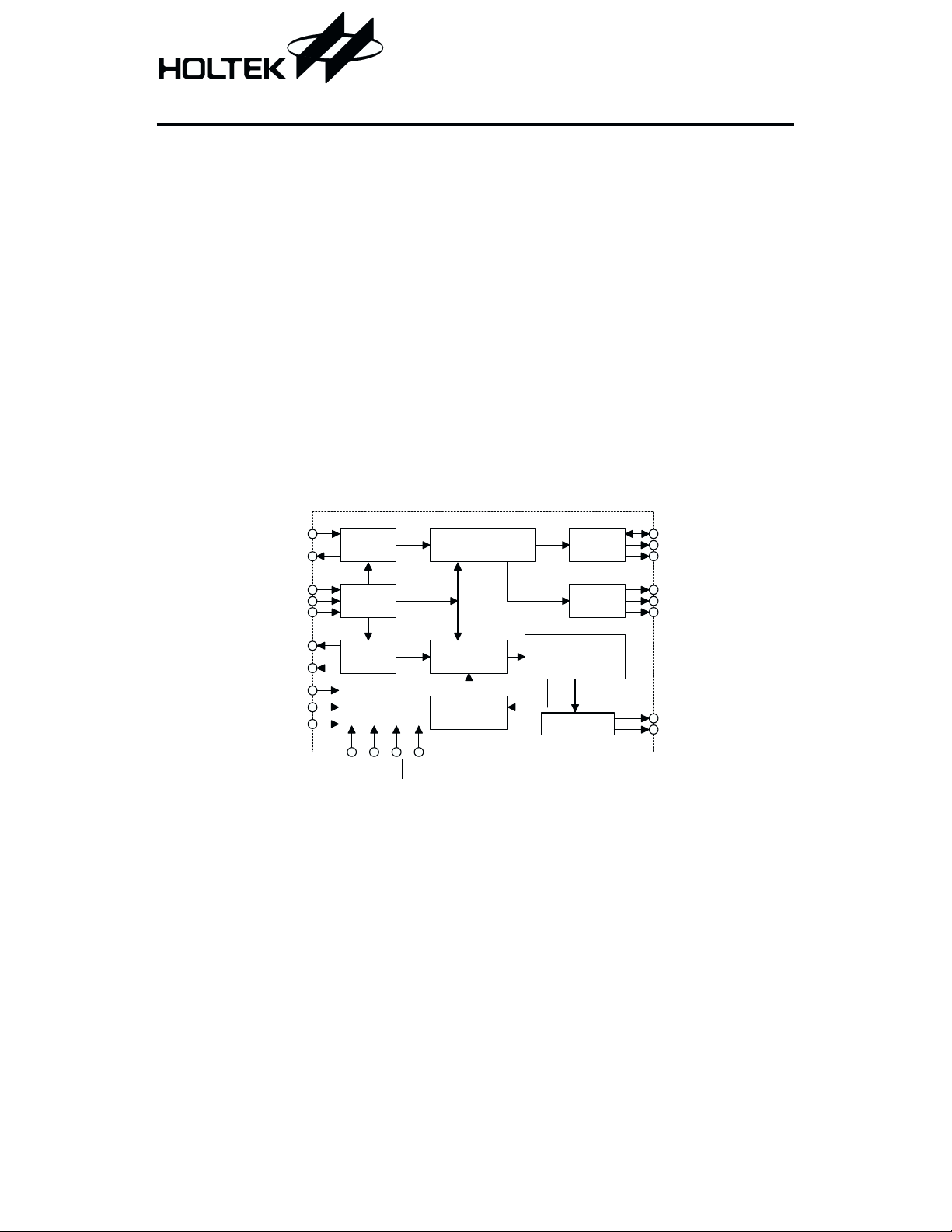
Block Diagram
HT7500
Clinical Thermometer
Alarm warning for fever
·
Highest temperature hold
·
Auto power off after 8 min 40 sec
·
One-key input switch for ON/OFF
·
Displays last time measured temperature
·
power off functions. The other electronic com
ponents are LCD display, thermister, 1.5V bat
tery, ON/OFF switch, buzzer, resistors and
capacitors.
-
-
OSCI
OSCO
TEST2
PSW
CLFH
RF
RS
SC
VDD
VSS
S ystem
OSC
C ontrol
Circuit
Sensor
OSC
TV
TEST1
C ounter and
C om parator
Pulse
G enerator
Pulse
Table
TIM
TS 816
1 August 8, 2000
TIM ER
Voltage
D oubler
C ounter ,
C om parator and
Latch
LCD Driver
LOW C
BZ1
BZ2
C 512
CAP
VEE
COM 1~3
SA1~SD1
Page 2
HT7500
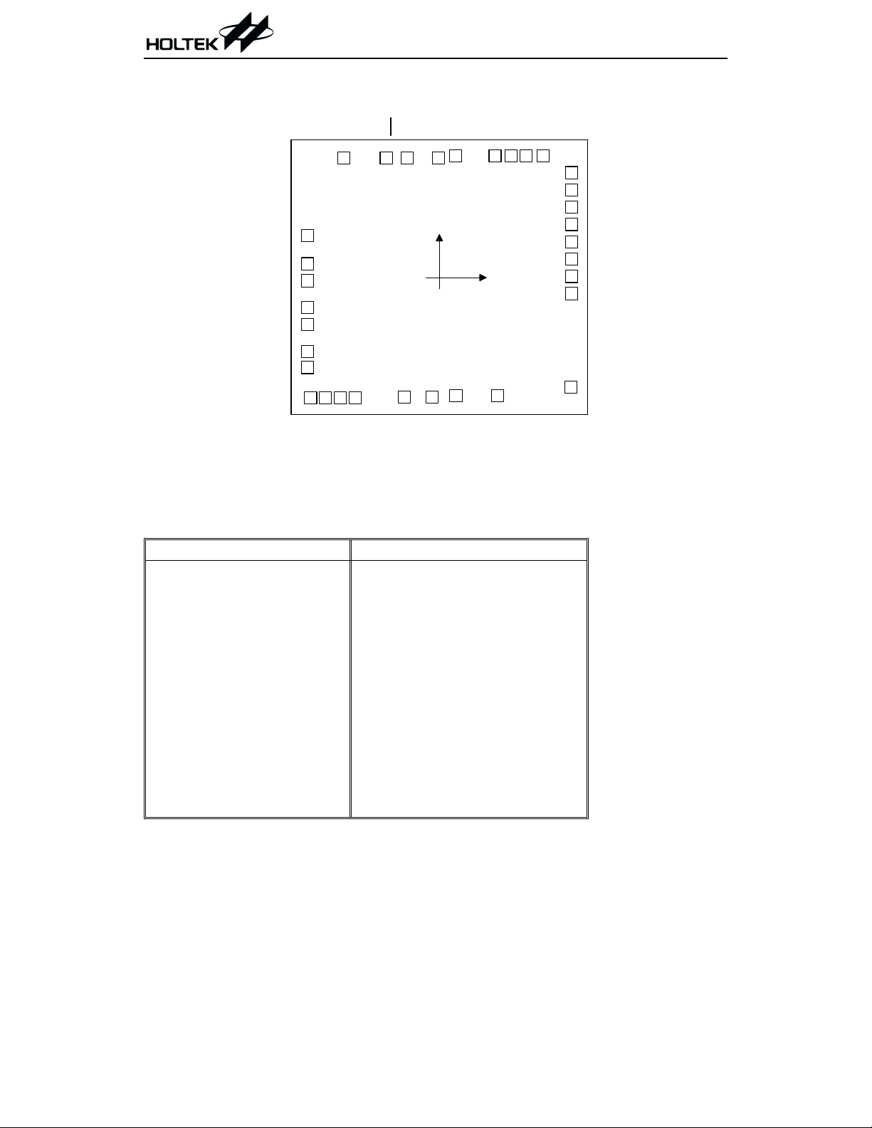
Pad Assignment
* The IC substrate should be connected to VDD in the PCB layout artwork.
L O W C
VSS
VDD
PSW
SC
RF
RS
TS 816
33
1
2
3
4
5
6
7
8
10
9
TEST2
CLFH
OSCI
OSCO
Chip size: 129 ´ 120 (mil)
TEST1
TIM
32
31
12
BZ1
C 512
CAP
VEE
SC3
TV
29
30
(0 ,0 )
14
13
BZ2
COM 1
SD1
25
26
271128
24
SC2
23
SC1
22
SB3
21
SB2
20
SB1
19
SA3
18
SA2
17
SA1
15
COM 2
2
16
COM 3
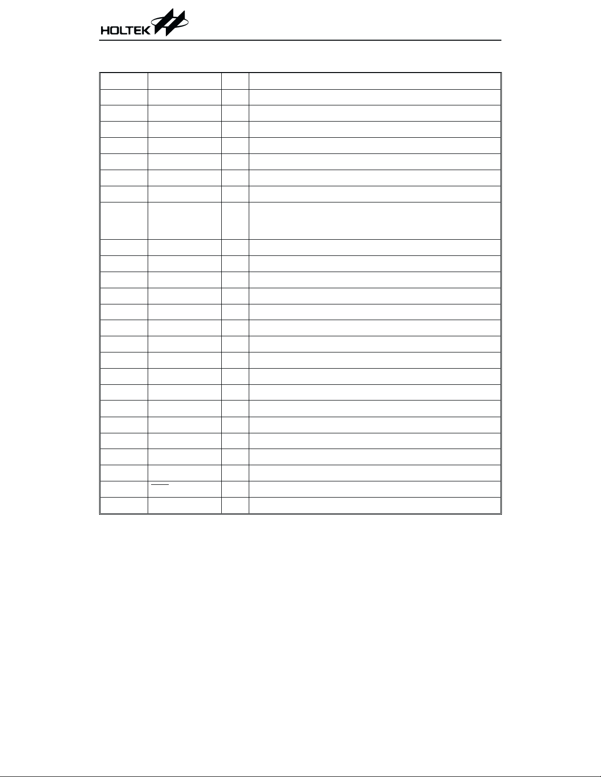
Pad Coordinates Unit: mil
Pin No. X Y Pin No. X Y
1
2
3
4
5
6
7
8
9
10
11
12
13
-58.61
-58.61
-58.61 -1.49
-58.61 -13.30
-58.61 -20.95
-58.61 -33.02
-58.61 -40.08
-57.25 -53.63
-50.62 -53.63
-43.99 -53.63
-37.36 -53.63
-15.64 -53.34
-3.19 -53.34
14 7.44
15 26.05
16 58.48
17 58.82
18.57 18 58.82 0.51
6.16 19 58.82 8.24
20 58.82 15.90
21 58.82 23.63
22 58.82 31.28
23 58.82 39.01
24 58.82 46.67
25 46.24 54.06
26 38.59 54.06
27 31.96 54.06
28 24.82 54.06
29 7.39 54.06
-52.66
-52.66
-48.75
30
31
32
33
-0.43
-14.28
-23.63
-42.33
53.29
53.29
53.29
53.29
-7.14
2 August 8, 2000
Page 3
HT7500
Pad Description
Pad No. Pad Name I/O Function
1 LOWC B For the supply voltage detector, open the pin when not in use.
2 VSS I Power supply GND
3 SC B Common point, NMOS open drain
4 RF O Connect reference resistor, PMOS open drain
5 RS O Connect sensor resistor, PMOS open drain
6 VDD
7 PSW I Pull-low input pin, push switch to turn power on or off
8 TEST2 I
9 CLFH I
10 OSCI I For system oscillator in
11 OSCO O For system oscillator out
12 BZ1 O Buzzer output 1
13 BZ2 O Buzzer output 2
14~16 COM1~COM3 O LCD backplane drive, 3-level voltage out
17~19 SA1~SA3 O LCD segment drive
20~22 SB1~SB3 O LCD segment drive
23~25 SC1~SC3 O LCD segment drive
26 SD1 O LCD segment drive
27 VEE O
28 CAP O For negative voltage, NMOS output
29 C512 O For negative voltage, inverter output
30 TV B Test pin for IC
31 TEST1 I Test pin for IC
32 TIM
33 TS816 I Test pin for IC
Positive power supply
¾
Pull-low test pin, for production test, floating LCD displays
the real time value, when connected to VDD, LCD displays
the highest value.
Floating for °C, connect to VDD for °F
Generate negative voltage (-1.5V)
I Test pin for IC
3 August 8, 2000
Page 4

Absolute Maximum Ratings
Supply voltage ...................................0V to 2.0V
Operation Temperature ...........-2.0°Cto+75°C
HT7500
Input voltage .................V
Storage Temperature ..............-55°C to +125°C
-0.5V to VDD+0.5V
SS
Note: These are stress ratings only. Stresses exceeding the range specified under ²Absolute Maxi
mum Ratings² may cause substantial damage to the device. Functional operation of this device
at other conditions beyond those listed in the specification is not implied and prolonged expo
sure to extreme conditions may affect device reliability.
Electrical Characteristics
Ta=25°C
Test Conditions
Symbol Parameter
V
DD
I
DD
I
STB
f
OSC
R°C
R°F
Operating Voltage
Operating Current 1.5V No load
Standby Current 1.5V
Oscillating Frequency 1.5V
Temperature Measurement
Accuracy at Range 35°C~39°C
Temperature Measurement
Accuracy at Range 95°F~102°F
DD
Conditions
V
¾¾
¾¾¾
=820kW
R
OSC
¾¾-0.1 ¾
¾¾-0.2 ¾
Min. Typ. Max. Unit
1.3 1.5 1.65 V
¾
60 100
1.0
mA
mA
25.6 32 38.4 kHz
0.1
0.2
°C
°F
LCD Electrode Pattern
H1 F1
H1
E1
A1
B1
G1
C1
D1
A2 A3
F2 F3
E2 E3
B2 B3
G2 G3
C2 C3
D2 D3
H2
A4
B4
C4
H3
-
-
SA1 SA2 SA3 SB1 SB2 SB3 SC1 SC2 SC3 SD1
COM1 F1 A1 B1 F2 A2 B2 F3 A3 B3 A4
COM2 E1 G1 C1 E2 G2 C2 E3 G3 C3 B4
COM3 H1 D1
¾¾
D2 H2
¾
D3 H3 C4
Note: 1/3 duty, 1/2 bias (LCD uses 3V)
4 August 8, 2000
Page 5

Function Description
·
Power sw: push switch to power on or power
off.
·
When power on: push the switch, then it will
generate a ²beep² sound for 0.125 sec.
a. First displays all the segments on for 2 sec.
b. After a. as described above, then shows the
last time measured temperature for 2 sec.
c. After b., shows L °Cor °F for 0.75 sec.
d. After c., displays the measured temperature,
then °Cor°F mark will flash at a speed of 1Hz.
e. If the temperature is < 32°C (or 90°F), the
display shows L °C (or °F).
f. If the temperature ³ 42°C (or 108°F the
display shows H °C (or °F).
g. The display always shows the higher
temperature during the temperature
measurement.
h. If the measured temperature does not
change for more than 16 sec., the measurement is over and the °C (or °F) mark flash
stops.
i. When measurement is over, if the
temperature > 37.5°C (or 99.5°F) the
buzzer alarms ²beep-beep-beep-beepbeep-beep-² for 4 sec, as follows:
BI BI
0.125S 0.125S 0.125S 0.125SBI0.125S 0.125S 0.375S
HT7500
j. It will automatically turn the power off when
measurement is over for 8 min 40 sec.
k. When measurement is over, but if the
temperature rises within 8 min 40 sec, the
°C (or °F) mark will flash again (repeat
from step 2-d), and starts to count 8 min
40 sec again.
l. When beep sound is on for 4 sec, the
temperature is not measured.
·
When power off: the standby current £ 1mA.
·
The frequency of the buzzer is 5.3kHz
·
Bonding option °Cor°F
·
Measurement to 0.1 degree in either °Cor°F
·
Sensor use 503ET
·
Reference resistor is the value
(sensor in 37.0°C)
·
When battery voltage is low, the battery mark
Ñ flashes at the speed of 1Hz and the mea
surement may not be accurate. The low volt
age detect: 1.35V ± 0.05V.
·
During the process of mass production, in order to adjust the reference resistance (RF), let
test 2 be floating, the measured temperature
will be the actual temperature of the measured environment. It can be up or down, not
always the higher one.
-
-
if the temperature £ 37.5°C (or 99.5°F), the
buzzer alarms ²beep-beep-beep-beep-² for
4 sec, as follows:
BI
0.5S 0.5S
5 August 8, 2000
Page 6

Flow Chart
HT7500
Power On
Display
L C
D isplay All S egm ent
D isplay Last M easured
Tem perature
D isplay L C
M easure
D isplay the
H ighest Value
Display
N ot C hanged for
O ver 16 sec
Alarm
2 sec
2 sec
0.75 sec
Display
H C
No
C N ot Flash for 4 sec
(C a n 't M e a s u re )
Yes
Tem perature
R ises w ithin
8 m in 40 sec
No
Power Off
6 August 8, 2000
Page 7

Application Circuits
HT7500
C 512
CAP
VEE
SD1
COM 3
COM 2
COM 1
0.022mF
0.022mF
To LCD
1.5V
Battery
400k
2200~2700pF
R
B uzzer
W
REF
SENSO R
=820k
OSC
W
LOW C
VSS
SC
RF
RS
VDD
PSW
TEST2
CLFH
OSCI
OSCO
BZ1
BZ2
SC1~3
SB1~3
SA1~3
0 6%#
Note: Substrate connect to VDD
VEE, CAP, and C512 are externally connected to capacitors for stabilizing V
EE
BZ1 and BZ2 are connected to an external buzzer to generate sounds.
LOWC is connected to an external resistor for adjusting the detector level of a low voltage de
tector. Open the pin when not in use.
OSCI, OSCO are connected to an external resistor, and form an RC oscillator with a built-in
capacitor for SYSTEM clock (=32kHz)
RS, RF, SC constitute an alternating RC oscillator, which allows one oscillator, namely RS or
RF, active at a time.
REF (reference resistor) is a resistor value equal to 503ET, sensor is value in 37.0 °C or 98.6 °F.
SENSOR is a 503ET thermistor.
(=-1.5V).
-
7 August 8, 2000
Page 8

HT7500
Holtek Semiconductor Inc. (Headquarters)
No.3 Creation Rd. II, Science-based Industrial Park, Hsinchu, Taiwan, R.O.C.
Tel: 886-3-563-1999
Fax: 886-3-563-1189
Holtek Semiconductor Inc. (Taipei Office)
5F, No.576, Sec.7 Chung Hsiao E. Rd., Taipei, Taiwan, R.O.C.
Tel: 886-2-2782-9635
Fax: 886-2-2782-9636
Fax: 886-2-2782-7128 (International sales hotline)
Holtek Semiconductor (Hong Kong) Ltd.
RM.711, Tower 2, Cheung Sha Wan Plaza, 833 Cheung Sha Wan Rd., Kowloon, Hong Kong
Tel: 852-2-745-8288
Fax: 852-2-742-8657
Copyright Ó 2000 by HOLTEK SEMICONDUCTOR INC.
The information appearing in this Data Sheet is believed to be accurate at the time of publication. However, Holtek
assumes no responsibility arising from the use of the specifications described. The applications mentioned herein are
used solely for the purpose of illustration and Holtek makes no warranty or representation that such applications
will be suitable without further modification, nor recommends the use of its products for application that may pres
ent a risk to human life due to malfunction or otherwise. Holtek reserves the right to alter its products without prior
notification. For the most up-to-date information, please visit our web site at http://www.holtek.com.tw.
8 August 8, 2000
-
 Loading...