

Page 1

USERS’ MANUAL
September 1997
HSP50307EVAL1
Burst QPSK Modulator Evaluation Board
Features
• 256 KBPS Transmit Data Input via BNC Connector;
Enable Input via BNC Connector
• 256kHz Transmit Clock Output via BNC Connector
(with RS422 Compatible Drive Level)
• Programmable 8MHz to 20MHz Synthesizer Reference
Oscillator for Modulated RF Output with 32kHz
Resolution
• Onboard 51.2MHz Crystal Oscillator with Internal
Dividers for MCLK and RCLK Source Plus BNC Connector for External Reference Source
• BNC Connector for External 25.6MHz Source of RCLK
• BNC Connector for External 2.048MHz Source of MCLK
• Burst QPSK Modulator with Square Root of Raised
Cosine Filtering (
• Programmable 40dB RF Output Level Range from
22dBmV to 60dBmV in 1dB Steps
• Standard Parallel Port Control Interface to PC
• Menu Driven Evaluation Board Software for Configuration and Control
• Software Runs on PC XT , AT or 100% Compatible (386,
486, Pentium) Machines Running DOS 3.0 or Higher
• Orcad Schematic Files Included On Distribution Disk
α = 0.5)
Description
The HSP50307EV AL1 e v aluation board is a platform f or quickly
evaluating the performance of the HSP50307 Burst QPSK
Modulator. The board includes a clock reference oscillator, reference divider circuitry, data interface buffers, a PC compatible
parallel port interface, differential to single ended conversion
circuitry, and the HSP50307 Burst QPSK Modulator.
The evaluation board is a four layer, 4" x 6" printed wire
board (PWB). The board stackup consists of two signal layers, a power plane lay er and a g round la yer. BNC connectors
are provided for the transmit data input, the transmit enable
input, the transmit clock output, the 51.2MHz Reference output, the 2.048MHz (MCLK) reference input, the 25.6MHz
(RCLK) reference input, and the RF output. Four 2.5mm
jacks are provided for the power supply inputs: +5V digital,
+5V analog, +9V analog, and -5.2V analog.
Clock Generation
Two clocks are required b y the HSP50307: a synthesizer reference clock, RCLK (nominally 2.048MHz), and a 100 times
the data rate clock, MCLK (nominally 25.6MHz). These two
clocks can be deriv7-ed from the 51.2MHz onboard oscillator or directly sourced externally via the J2 and J3 BNC connectors, or derived from an external 51.2MHz input through
J4. Jumpers determine the source of each clock. When and
external 51.2MHz reference is used, JP3 can be installed to
terminate this J4 input in 50Ω. JP3 is located between J4
and the 51.2MHz reference oscillator , U3. (See Appendix C.)
Note: Use of the external reference requires that the
onboard oscillator be removed from the socket.
HSP50307EVAL1 Evaluation Board Block Diagram
25.6MHz
J2
INPUT
/2
2.048MHz
J3
INPUT
51.2MHz
J4
INPUT
51.2MHz
REFERENCE
J
PARALLEL
P
1
PORT
TX_DATA
J5
TX_EN
J6
TXCLK
J7
NOTE: One of two paths are installed. Kits for other path are included with the evaluation board.
CAUTION: These devices are sensitive to electrostatic discharge; follow proper IC Handling Procedures.
http://www.intersil.com or 407-727-9207
| Copyright © Intersil Corporation 1999
/25
CONTROL
REGISTER
M
MCLK
U
X
M
RCLK
U
X
HSP50307
BURST
QPSK
MODULATOR
7-76
(NOTE)
OP-AMP
PATH
XFORMER
PATH
(NOTE)
J1
RFOUT
File Number 4239.1
Page 2

HSP50307EVAL1
The clock generation circuitry derives the two required clocks
from either the 51.2MHz crystal oscillator (U3) or the external
reference (J4). Two ACT74 flip-flops (U4) implement a divide
by 2 to yield the 100 times data (25.6MHz) clock, RCLK. A
divide by 12/13 combines with a divide by two (U4 and U5) to
yield a divide by 25, generating the 2.048MHz clock.
The two onboard reference derived clocks, and the J2 and
J3 inputs are routed to header JP2. Header JP2 is located
near U4 pins 7 and 8. Jumpers are used to select the
on-board or external clock source for the HSP50307. When
using the external sources, the dividers can be disabled by
installing JP4. This holds the clear signal inputs to the divide
by 2 circuits low. Table 1 details the JP2 settings for various
clock source configurations. R14 and 15, located between
header JP2 and the HSP50307, are series terminating
resistors to minimize ringing on the clock signals.
TABLE 1. HEADER JP2 CLOCK SOURCE SELECTION
INSTALL
CLOCK SOURCE
MCLK
(2.048MHz)
MCLK
(2.048MHz)
RCLK
(25.6MHz)
RCLK
(25.6MHz)
Divide By 25
(U4B and U5)
External
(J2)
Divide By 2
(U4A)
External
(J3)
JUMPER
3-4
1-2
7-8
9-10
Data Interface
Three BNC connectors, JP5, 6, and 7, provide the interface
for transmit data, transmit clock and transmit enable. Signal
drive and receive buffers are used to isolate these signals
from the external equipment. The line receivers are 26LS32
(RS422 type) with one input biased to approximately 1.6V.
The outputs will be high if no signal is applied to the input
connectors. Installing JP5 provides 100Ω termination for the
transmit data input at J5. JP5 is located near U8 pin 9.
Installing JP6 provides 100Ω termination for the transmit
enable input at J6. JP6 is located near U7 pin 9. The clock
driver is a 26LS31 (RS422 type) using a single ended output.
Appendix C details all the jumper pin assignments.
PC Interface
The board is designed to interface to a standard PC parallel
port (LPT por t). The software provided with the board allows
the user to select the LPT port number, carrier frequency,
output attenuation, and several chip test options. The menu
screen is shown in Figure 1. To run software, load distribution disk and type
modevb
at the DOS command line.
The options are edited via menu items 1-8. When all the
options have been entered, menu item 9 computes the serial
data bits and programs the part.
The cable connecting the evaluation board to the PC is
attached at JP1 with the cable facing aw ay from the board. A
74ACT574 buffers the incoming signal from the PC. This
implements a half duplex serial interface from the PC to the
board, even though the parallel port is being used. SERCLK,
SERDATA, SEREN and RESET originate on different parallel port pins. A code listing of the Evaluation Board Software
is provided in Appendix A.
EDIT PARAMETERS:
(1) LPT Number: .................... 2
(2) Reference Frequency: 2048000
(3) Output Frequency: 8096000
(4) Synthesizer Enable Bit: ........ 1
(5) Current Level Bit: ............. 0
(6) Three State Bit: .................. 0
(7) Output Attenuation: ............ 6
(8) Test Mode: ..................... 0
(9) Program Modulator
(10) Reset Modulator
(11) Exit
ENTER SELECTION:
M = 41 A = 1
b0 to b9 => 1 0 0 1 0 0 1 0 1 0
b10 to b12 => 1 0 0
b13 to b18 => 0 1 1 0 0 0
b19 to b21 => 0 0 0
FIGURE 1. SOFTWARE EVALUATION BOARD MENU OPTIONS
HSP50307
The HSP50307EVAL1 hardware includes the HSP50307,
four power supply decoupling chip capacitors (C3, 6, 7, 12);
two reference decoupling capacitors (C4 and C5); two
baseband AC coupling capacitors (C1 and C2); a VCO
current setting resistor; and the synthesizer loop filter
components (two capacitors (C8 and C9); a resistor (R3),
and an optional bleed resistor (R4). The evaluation board
parts list is given in Table 2. The PWB layout is provided in
Appendix B. The components for the RF Output are
discussed in the next section.
7-77
Page 3
HSP50307EVAL1
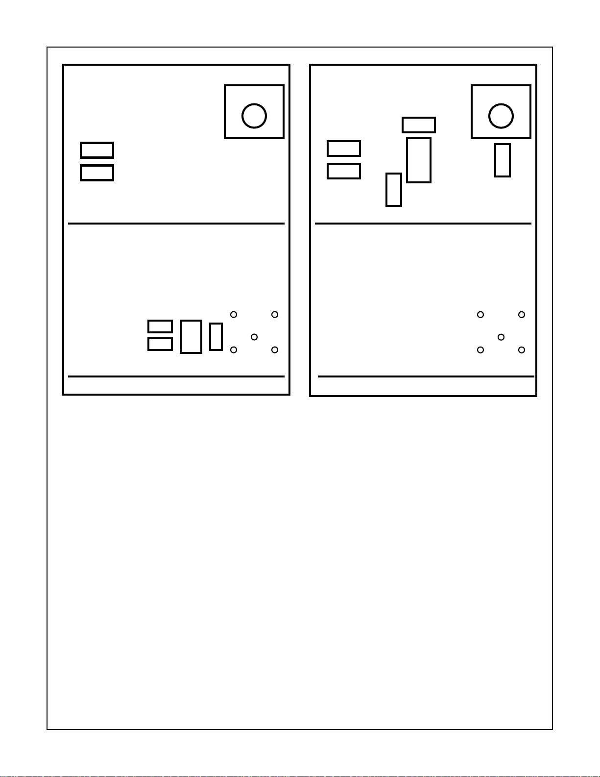
TOP LAYER
R7
R29
R30
R5
BOTTOM LAYER
C25
C26
C25
C26
U9
RFTN1
R31
R31
RFOUT
RF
OUT
TOP LAYER
R7
R7
R5
R5
BOTTOM LAYER
R6 R6
R8
R8
HFA1100
U2
RFOUT
R9
R9
RF
OUT
PARTS YOU DO NOT INSTALL: R7, R5, U2, R9, R8, R6
FIGURE 2. PARTS THAT NEED TO BE INST ALLED FOR RF
TRANSFORMER OUTPUT MODE
RF Output
Two RF output configurations are provided: 1) use of an operational amplifier or 2) use of an RF transformer.
Op Amp Output Drive
For the operational amplifier configuration, the differential
output of the HSP50307 is loaded with a 150Ω resistor and
two 37.5Ω matching resistors to simulate a 75Ω load. The
HSP50307 output is converted to single ended using an op
amp. The op amp drives the output RF BNC through a 50Ω
matching resistor to allow easy interfacing to test equipment.
The devices that need to be installed for operation amplifier
mode are shown in Figure 2.
PARTS YOU DO NOT INSTALL: R29, R30, C25, C26, U9, R31
FIGURE 3. PARTS THAT NEED TO BE INST ALLED FOR OP
AMP OUPUT MODE
RF Transformer Output Drive
For the RF transformer configuration, the differential output
of the HSP50307 is loaded with a 0.1µF capacitor and 38Ω
resistor for AC coupling and impedance matching. The
output of the 1:1 RF transformer is loaded with a 75Ω
output impedance; one leg of the differential output of the
RF transformer is grounded, providing a single ended
output to the RF BNC connector. The devices that need to
be installed for RF transformer mode are shown in
Figure 3.
7-78
Page 4

HSP50307EVAL1
TABLE 2. EVALUATION BOARD PARTS LIST
REF DES PART NUMBER DESCRIPTION MANUFACTURER
U1 HSP50307 Burst QPSK Modulator INTERSIL
1
U2
U3 CO6100-51.200 Oscillator, 51.20MHz; HCMOS, 14 Pin, 100ppm
U4 CD74ACT74E Dual Flip-Flop INTERSIL
U5 CD74ACT169E Up/Down Counter INTERSIL
U6 CD74ACT574 Octal Register INTERSIL
U7 AM26LS32AC Differential Receiver TI
U8 AM26LS31C Differential Driver TI
JP1 PTC13DAAN 2 x 13 Pin Header (PC interface) SULLINS
JP2 PTC05DAAN 2 x 5 Pin Header (Clocking Configuration) SULLINS
JP3-6 PTC01DAAN 2 Pin Power Header (Terminating/EN PullDown) SULLINS
J1-7 4578 BNC, PWB Mount PAMONA
J8-11 DJ005 Power Jacks LZR
RZ1 4610X-101-223 22K Resistor Pack 10 Pin SIP BOURNS
C1, 2 ECU-S1J225MEB 2.2µF, Ceramic PANASONIC
C3, 6, 7, 10
C4, 5, 8 ECU-S2A103JCB 0.01µF, Ceramic PANASONIC
C9 ECU-S2A221JCB 100pF, Ceramic PANASONIC
C13-16, C18, 20 A223M15Z5UFVVWE 0.022µF 50V (0.1µF 50V was used on some boards) PHILLIPS
C17, 19, 21, 22 ECS-F1VE106K 10µF 35V PANASONIC
R1 6.2kΩ, 1/8W DALE
1
R2
R3, 24, 25 2.2kΩ, 1/8W DALE
R4 1MΩ, 1/8W (Not installed - packed separately) DALE
1
R5
1
R6
1
R9
R14-17 100Ω, 1/4W DALE
R18-21 1Ω, 1/4W (for power supply filtering) or Wire Jumper DALE
26, 27 2.0kΩ, 1/8W DALE
R28 Not Used Not Used Not Used
SHORTING JUMPER KIT
SJ1-6 3200SU00001
TRANSFORMER OUTPUT KIT
U9 RFTN-1 RF Transformer RF PRIME
C23, 24 47pF PANASONIC
C25, 26 0.1µF, Ceramic
R29, 30 (placed in R5 and
R7 locations)
R31 75Ω, 1/4W DALE
NOTES:
1. These parts constitute the op amp output drive circuitry. If you are using the transformer output circuitry, you will need to install the Trans-
2. HSP50307EVAL1 includes 4 DC power supply cables, 26 pin ribbon cable, distribution disk, and HSP50307EVAL-board. Load software
1
, 111, 2 ECW-U1H123JB5 0.012µF Surface Mount PANASONIC
, 71, 13, 22, 23 1kΩ, 1/8W DALE
1
, 8
, R10-12 49.9Ω, 1/4W DALE
former Output Kit parts and remove R9 to avoid output contention.
into your PC and type
HFA1100 Op Amp INTERSIL
Frequency Stability; 40% - 60% Symmetry
150Ω, 1/4W DALE
510Ω, 1/8W DALE
Shunts; Shorting Jumper (Not installed on Board) LEOCO
(S9000-ND)
38Ω, 1/8W DALE
Modevb
at the DOS prompt. The
dsn
directory contains the ORCAD schematics.
RALTRON
(DIGIKEY)
7-79
Page 5

Evaluation Board Schematic
HSP50307EVAL1
TXCLK
J8
JACK
GND
J5
BNC
GND
2
R25
R
A
R17
R
GND
VDD
JP6
1
2
HEADER 2
R23
R
GND
GND
U7
2
1A
1
1B
6
2A
7
2B
10
3A
9
3B
14
4A
15
4B
12
G
4
G
AM26LS32AC
U8
1
1A
7
2A
9
3A
15
4A
12
G
4
G
AM26LS31C
1Y
1Z
2Y
2Z
3Y
3Z
4Y
1Y
2Y
3Y
4Y
Z
V
3
5
11
13
2
3
6
5
10
11
14
13
V
CC
R26RR27
CC
R
TXDATA
TXEN
J7
BNC
1
2
GND
2
R18
R16
R
JP5
1
2
HEADER 2
1
V
CC
R25
R22
R
GND
R
C22
10µF
AGND
GND
1
J6
BNC
2
GND
1
J11
JACK
GND
J10
JACK
GND
A
VCC
C13
0.1µF
C18
0.1µF
J9
JACK
GND
1
2
C17
0.1µF
R19
R
C16
0.1µF
C15
0.1µF
C21
10µF
AGND
C14
0.1µF
-5V
1
2
1
2
R21
R20
R
R
AGND
GND
C19
10µF
C20
10µF
V
CC
GND GND GND GND GND GND
7-80
Page 6
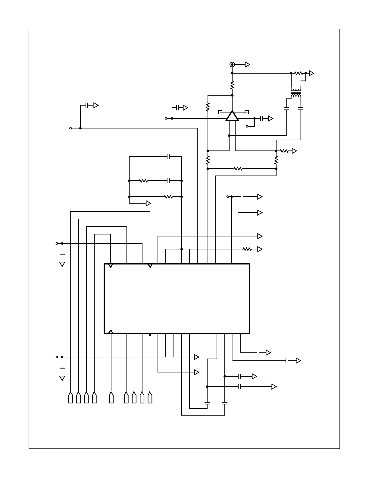
HSP50307EVAL1
Evaluation Board Schematic
C6
CAP NP
AGND
VCC
A
(Continued)
R3
R
AGND
-5V
C9
CAP NP
C8
CAP NP
R4
R
C11
CAP NP
AGND
R8
R7/R29
BNC
U2
45
VDD
A
2
R31
1
R9
6
+
-
2
3
R
R2
71
VCC
A
R
C7
CAP NP
AGND
C10
CAP NP
R5
AGND AGND
R30
C25
AGND
R6
R
75Ω
AGND
U9
TRANS-
FORMER
0.1µF
C26
0.1µF
R
AGND
J1
R
R
C12
CAP NP
C3
CAP NP
CC
V
VCC
A
GND
REFCLK
AGND
SEREN
SERDATA
U1
SERCLK
28
2726252423
SERCLK
CLK _26
1
2
25P6CLK
TXCLK
SEN
VCC5D1
SERDATA
PSKTXCLK
PSKTXEN
PSKDATA
3
4
TXEN
TXDATA
GND5A3
PSKREFIN
RESET
GND5D1
5
678
RESET
22
PHDETOUT
VCC5A1
212019
VCO_IN
GND5A1
IDATOUT
9
IDATOUT
ODATOUT
VCC5A3
VCO_SET
QDATOUT
10
18
17
MODOUT+
111213
AGNDDGND
C1
CAP NPC2CAP NP
MODOUT-
QDATIN
16
IDATIN
15
VDD9A2
GND9A2
DAC_REF
VCM_REF
14
C23
47pF
C24
47pF
R1
R
PSKMOD
C4
AGND GND
CAP NP
AGND
AGND
C5
AGND
CAP NP
AGND
SEREN
REFCLK
SERDATA
SERCLK
25P6CLK
TXEN
TXCLK
TXDATA
RESET
7-81
Page 7

HSP50307EVAL1
Evaluation Board Schematic
SERCLK
SERDATA
SEREN
19181716151413
Q1Q2Q3Q4Q5Q6Q7
U6
D1D2D3D4D5D6D7
GND
JP1
26
24
22
20
18
16
14
12
10
8
6
4
2
HEADER 13 x 2
25
23
21
19
17
15
13
11
9
7
5
3
1
2345678
(Continued)
RESET
12
9
Q8
D8
REFCLK
25P6CLK
100
R14
246
74ACT574
CLK
OC
1
11
GND
1
J2
BNC
2
JP2
13579
51
R11
GND
8
R10
R15
10
100
HEADER 5 x 2
51
1
J3
BNC
GND GND
GND
2
GND
2345678910
1
R1R2R3R4R5R6R7R8R9
COM
RZ1
GND
JP3 JP4
51
R12
DIVIDER
DISABLE
1
2
HEADER 2
TERMINATION
RESISTOR
1
2
HEADER 2
CC
V
GND
RSIP10
R13
GND
R
U4A
4
98U4B
Q
13
CL
DPRQ
CLK
12
11
1413121115
QAQBOC
OD
5
6
74ACT74
Q
CL
DPRQ
CLK
2
3
U5
ABC
345
RCO
D
6
291107
CLK
LOAD
D
U/
ENT
ENP
74AC169
GND
U3
8
OUT
OSC
51.2MHz
CC
V
1
2
J4
BNC
GND
NOTE: Counter Alternates between preloads of 3 and 4 (for periods of 12 and 13). Combined with the divide by 2, this gives a total divide by
25 with close to a 50% duty cycle.
7-82
Page 8

HSP50307EVAL1
Appendix A: Evaluation Board Software
/* HSP50307 test board programming program */
/* board is programmed via parallel port (data port) */
/* LPT1 is I/O address 3BCh */
/* LPT2 is I/O address 378h */
/* LPT3 is I/O address 278h */
/* outportb(I/Oaddr,data) is turboC command */
/* for example: outportb(0x27a,0x00); */
/* data port bit 0 is register write clock */
/* clocks data into ACT574 on 0 to 1 write, leave low */
/* after write */
/* data port bit 7 is control clock */
/* data port bit 6 is control data */
/* data port bit 5 is control enable */
/* data port bit 4 is reset (active low) */
/* control bits are loaded serially starting with the bit 0 */
/* data is clocked into the master shift register on the falling */
/* edge of clock */
/* control enable is brought high at the start of the load */
/* and brought back low after the last bit to latch the data */
/* into the slave holding register */
/* */
/* Count = 6 * ( M + 1 ) + A */
/* */
/* configuration bits */
/* bit 0 --- A0 freq control */
/* bit 1 --- A1 */
/* bit 2 --- A2 */
/* bit 3 --- M0 */
/* bit 4 --- M1 */
/* bit 5 --- M2 */
/* bit 6 --- M3 */
/* bit 7 --- M4 */
/* bit 8 --- M5 */
/* bit 9 --- M6 freq control */
/* bit 10 -- SEN synth en */
/* bit 11 -- Icp charge pump current */
/* bit 12 -- T tristate option */
/* bit 13 -- ATT0 */
/* bit 14 -- ATT1 */
/* bit 15 -- ATT2 */
/* bit 16 -- ATT3 */
/* bit 17 -- ATT4 */
/* bit 18 -- ATT5 */
/* bit 19 -- TST0 */
/* bit 20 -- TST1 */
/* bit 21 -- TST2 */
/* bit 22 -- TST3 */
/* */
#include <math.h>
#include <stdio.h>
#include <string.h>
#include <stdlib.h>
#include <io.h>
#include <conio.h>
#include <time.h>
#include <graphics.h>
#include <dos.h>
7-83
Page 9

#include <alloc.h>
#include <c:\projects\gi\mod\evalbrd\qpskmod.inc>
void main()
{
/* initialize variables and text screen setup */
ENDPROG = 2 ;
IMENU = 100 ;
textmode(C80);
window(1,1,79,24) ;
textbackground(BLUE);
clrscr();
textcolor(WHITE);
lptnum = 2 ;
refclk = 2.048e6 ;
freq = 8.096e6 ;
synthen = 1 ;
current = 0 ;
tristate = 0 ;
atten = 6 ;
testmode = 0 ;
m = 42 ;
a = 4 ;
HSP50307EVAL1
while(ENDPROG > 0 )
{
switch(IMENU)
{
case 100:
{
/* setup menu */
clrscr() ;
gotoxy( 4,2);
fprintf(stdout,"EDIT PARAMETERS: ");
gotoxy( 6,3);
fprintf(stdout,"(1) LPT Number: .................... %i ",lptnum );
gotoxy( 6,4);
fprintf(stdout,"(2) Reference Frequency: %ld ",refclk );
/* M and A counters */
divide = floor((8.0 * (double)freq)/((double)refclk / 8.0)) ;
m = floor(divide/6.0)-1 ;
a = floor(divide - 6 * (m + 1) ) ;
if (m > 127) m = 127;
if (a > 5) a = 5;
freq = (long)(refclk/64.0) * (6.0 * (m+1) + a);
gotoxy( 6,5);
fprintf(stdout,"(3) Output Frequency: %ld ",freq );
gotoxy( 4,19);
fprintf(stdout,"M = %i A = %i ",m,a );
gotoxy( 6,6);
fprintf(stdout,"(4) Synthesizer Enable Bit: ........ %i ",synthen );
dotages(6,7);
fprintf(stdout,"(5) Current Level Bit: ............. %i ",current );
gotoxy( 6,8);
fprintf(stdout,"(6) Tristate Bit: .................. %i ",tristate );
gotoxy( 6,9);
fprintf(stdout,"(7) Output Attenuation: ............ %i ",atten );
gotoxy( 6,10);
7-84
Page 10

HSP50307EVAL1
fprintf(stdout,"(8) Test Mode: ..................... %i ",testmode );
gotoxy( 4,12);
fprintf(stdout,"(9) Program Modulator" );
gotoxy( 4,13);
fprintf(stdout,"(10) Reset Modulator" );
gotoxy( 4,14);
fprintf(stdout,"(11) Exit" );
gotoxy( 4,16);
fprintf(stdout," ENTER SELECTION: " );
for (i=0;i<32;i++)
b[i] = 0 ;
mx = m;
ax = a;
attenx = atten;
if (mx >= 64) { b[9] = 1; mx=mx-64 ; }
if (mx >= 32) { b[8] = 1; mx=mx-32 ; }
if (mx >= 16) { b[7] = 1; mx=mx-16 ; }
if (mx >= 8) { b[6] = 1; mx=mx-8 ; }
if (mx >= 4) { b[5] = 1; mx=mx-4 ; }
if (mx >= 2) { b[4] = 1; mx=mx-2 ; }
if (mx == 1) { b[3] = 1; }
if (ax >= 4) { b[2] = 1; ax=ax-4 ; }
if (ax >= 2) { b[1] = 1; ax=ax-2 ; }
if (ax == 1) { b[0] = 1; }
if (synthen == 1) { b[10] = 1; }
if (current == 1) { b[11] = 1; }
if (tristate == 1) { b[12] = 1; }
if (attenx >= 32) { b[18] = 1; attenx=attenx-32 ; }
if (attenx >= 16) { b[17] = 1; attenx=attenx-16 ; }
if (attenx >= 8) { b[16] = 1; attenx=attenx-8 ; }
if (attenx >= 4) { b[15] = 1; attenx=attenx-4 ; }
if (attenx >= 2) { b[14] = 1; attenx=attenx-2 ; }
if (attenx == 1) { b[13] = 1; }
if (testmode == 0) {b[19] = 0; b[20] = 0; b[21] = 0;}
if (testmode == 1) {b[19] = 1; b[20] = 0; b[21] = 0;}
if (testmode == 2) {b[19] = 0; b[20] = 1; b[21] = 0;}
if (testmode == 3) {b[19] = 1; b[20] = 1; b[21] = 0;}
if (testmode == 4) {b[19] = 0; b[20] = 0; b[21] = 1;}
if (testmode == 5) {b[19] = 1; b[20] = 0; b[21] = 1;}
if (testmode == 6) {b[19] = 0; b[20] = 1; b[21] = 1;}
if (testmode == 7) {b[19] = 1; b[20] = 1; b[21] = 1;}
gotoxy( 4,20);
fprintf(stdout,"b0 to b9 => %i %i %i %i %i %i %i %i %i %i",
b[0],b[1],b[2],b[3],b[4],b[5],b[6],b[7],b[8],b[9]);
gotoxy( 4,21);
fprintf(stdout,"b10 to b12 => %i %i %i ",
b[10],b[11],b[12]);
gotoxy( 4,22);
fprintf(stdout,"b13 to b18 => %i %i %i %i %i %i",
b[13],b[14],b[15],b[16],b[17],b[18]);
gotoxy( 4,23);
fprintf(stdout,"b19 to b21 => %i %i %i",
b[19],b[20],b[21]);
gotoxy(25,16) ;
fscanf(stdin,"%s",&STR);
INPSEL = atoi(STR);
IMENU = INPSEL + 200 ;
break;
}
7-85
Page 11

HSP50307EVAL1
/* port number */
case 201:
{
clrscr();
gotoxy(5,5); fprintf(stdout,"Current Port is: %i",lptnum);
gotoxy(5,7); fprintf(stdout,"Enter New Port: ");
gotoxy(30,7); fscanf(stdin,"%i",&lptnum);
if (lptnum > 3) lptnum = 3;
if (lptnum < 1) lptnum = 1;
IMENU = 100;
break;
}
/* reference clock frequency nominal 2.048 MHz */
case 202:
{
clrscr();
gotoxy(5,5); fprintf(stdout,"Current Value: %ld",refclk);
gotoxy(5,7); fprintf(stdout,"Enter New Value: ");
gotoxy(30,7); fscanf(stdin,"%ld",&refclk);
IMENU = 100;
break;
}
/* frequency 8.00 - 20 MHz in 32 kHz steps */
case 203:
{
clrscr();
gotoxy(5,5); fprintf(stdout,"Current Value: %ld",freq);
gotoxy(5,6); fprintf(stdout," (frequency range is 8.0 - 20.128 MHz)");
gotoxy(5,8); fprintf(stdout,"Enter New Value: ");
gotoxy(30,8); fscanf(stdin,"%ld",&freq);
IMENU = 100;
break;
}
/* synthesizer enable -- 1 = enable */
case 204:
{
clrscr();
gotoxy(5,5); fprintf(stdout,"Current Value: %i",synthen);
gotoxy(5,6); fprintf(stdout," 1 = enable, 0 = disable");
gotoxy(5,8); fprintf(stdout,"Enter New Value: ");
gotoxy(30,8); fscanf(stdin,"%i",&synthen);
if (synthen > 1) synthen = 1;
IMENU = 100;
break;
}
/* p/f detector current level */
case 205:
{
clrscr();
gotoxy(5,5); fprintf(stdout,"Current Value: %i",current);
gotoxy(5,6); fprintf(stdout," 1 = 1 mA, 0 = 500 uA");
gotoxy(5,8); fprintf(stdout,"Enter New Value: ");
gotoxy(30,8); fscanf(stdin,"%i",¤t);
if (current > 1) current = 1;
IMENU = 100;
break;
}
7-86
Page 12

HSP50307EVAL1
/* phase/freq det tristate mode enable */
case 206:
{
clrscr();
gotoxy(5,5); fprintf(stdout,"Current Value: %i",tristate);
gotoxy(5,6); fprintf(stdout," 0 = enable, 1 = disable");
gotoxy(5,8); fprintf(stdout,"Enter New Value: ");
gotoxy(30,8); fscanf(stdin,"%i",&tristate);
if (tristate > 1) tristate = 1;
IMENU = 100;
break;
}
/* attenuation 0 - 40 in 1 dB steps */
case 207:
{
clrscr();
gotoxy(5,5); fprintf(stdout,"Current Value: %i",atten);
gotoxy(5,6); fprintf(stdout," (values from 0 to 40 are valid)");
gotoxy(5,8); fprintf(stdout,"Enter New Value: ");
gotoxy(30,8); fscanf(stdin,"%i",&atten);
if (atten > 40) atten = 40 ;
IMENU = 100;
break;
}
/* test mode 0 - 7 */
case 208:
{
clrscr();
gotoxy(5,5); fprintf(stdout,"Current Value: %i",testmode);
gotoxy(5,6); fprintf(stdout, " 0 = Normal mode");
gotoxy(5,7); fprintf(stdout, " 1 = VCO divider test mode");
gotoxy(5,8); fprintf(stdout, " 2 = Reference divider test mode");
gotoxy(5,9); fprintf(stdout, " 3 = Filter/output stage test mode");
gotoxy(5,10); fprintf(stdout," 4 = Serial port test mode");
gotoxy(5,11); fprintf(stdout," 5 = Digital filter test mode");
gotoxy(5,12); fprintf(stdout," 6 = D/A test mode");
gotoxy(5,13); fprintf(stdout," 7 = n/a");
gotoxy(5,14); fprintf(stdout,"Enter New Value: ");
gotoxy(30,14); fscanf(stdin,"%i",&testmode);
if (testmode > 7) testmode = 7;
IMENU = 100;
break;
}
/* program modulator via lpt port */
case 209:
{
/* calculate bit values */
/* inactive condition write ( and latches in data ) */
/* serial clk low, data low, serial en low, reset high, clk low */
init1 = 16 + 0 ;
/* serial clk low, data low, serial en low, reset high, clk high */
init2 = 16 + 1 ;
/* reset condition write */
/* serial clk low, data low, serial en low, reset low, clk low */
reset1 = 0 ;
/* serial clk low, data low, serial en low, reset low, clk high */
7-87
Page 13

HSP50307EVAL1
reset2 = 1 ;
/* NOTE: An extra clock with data low is required before bringing
serial en low! This is test bit 3 (dsp disable) */
switch(lptnum)
{
case 1:
{
outportb(0x3bc,init1);
outportb(0x3bc,init2);
outportb(0x3bc,init1+32);
outportb(0x3bc,init2+32);
for (i=0;i<23;i++)
{
/* serial clk low, data out, serial en high, reset high, clk low */
data1 = 0 + (b[i] * 64) + 32 + 16 + 0 ;
/* serial clk low, data out, serial en high, reset high, clk high */
data2 = 0 + (b[i] * 64) + 32 + 16 + 1 ;
/* serial clk high, data out, serial en high, reset high, clk low */
data3 = 128 + (b[i] * 64) + 32 + 16 + 0 ;
/* serial clk high, data out, serial en high, reset high, clk high */
data4 = 128 + (b[i] * 64) + 32 + 16 + 1 ;
outportb(0x3bc,data1);
outportb(0x3bc,data2);
outportb(0x3bc,data3);
outportb(0x3bc,data4);
outportb(0x3bc,data1);
outportb(0x3bc,data2);
}
outportb(0x3bc,init1);
outportb(0x3bc,init2);
outportb(0x3bc,init1);
break;
}
case 2:
{
outportb(0x378,init1);
outportb(0x378,init2);
outportb(0x378,init1+32);
outportb(0x378,init2+32);
for (i=0;i<23;i++)
{
/* serial clk low, data out, serial en high, reset high, clk low */
data1 = 0 + (b[i] * 64) + 32 + 16 + 0 ;
/* serial clk low, data out, serial en high, reset high, clk high */
data2 = 0 + (b[i] * 64) + 32 + 16 + 1 ;
/* serial clk high, data out, serial en high, reset high, clk low */
data3 = 128 + (b[i] * 64) + 32 + 16 + 0 ;
/* serial clk high, data out, serial en high, reset high, clk high */
data4 = 128 + (b[i] * 64) + 32 + 16 + 1 ;
outportb(0x378,data1);
outportb(0x378,data2);
outportb(0x378,data3);
outportb(0x378,data4);
outportb(0x378,data1);
outportb(0x378,data2);
}
outportb(0x378,init1);
outportb(0x378,init2);
outportb(0x378,init1);
7-88
Page 14

HSP50307EVAL1
break;
}
default: /* lpt 3 */
{
outportb(0x278,init1);
outportb(0x278,init2);
outportb(0x278,init1+32);
outportb(0x278,init2+32);
for (i=0;i<23;i++)
{
/* serial clk low, data out, serial en high, reset high, clk low */
data1 = 0 + (b[i] * 64) + 32 + 16 + 0 ;
/* serial clk low, data out, serial en high, reset high, clk high */
data2 = 0 + (b[i] * 64) + 32 + 16 + 1 ;
/* serial clk high, data out, serial en high, reset high, clk low */
data3 = 128 + (b[i] * 64) + 32 + 16 + 0 ;
/* serial clk high, data out, serial en high, reset high, clk high */
data4 = 128 + (b[i] * 64) + 32 + 16 + 1 ;
outportb(0x278,data1);
outportb(0x278,data2);
outportb(0x278,data3);
outportb(0x278,data4);
outportb(0x278,data1);
outportb(0x278,data2);
}
outportb(0x278,init1);
outportb(0x278,init2);
outportb(0x278,init1);
break;
}
}
IMENU = 100 ;
break ;
}
/*--------------------------------------------------*/
/* reset part */
case 210:
{
clrscr();
switch(lptnum)
{
case 1:
{
outportb(0x3bc,reset1);
outportb(0x3bc,reset2);
outportb(0x3bc,init1);
outportb(0x3bc,init2);
break;
}
case 2:
{
outportb(0x378,reset1);
outportb(0x378,reset2);
outportb(0x378,init1);
outportb(0x378,init2);
break;
}
default: /* case 3 */
{
7-89
Page 15

outportb(0x278,reset1);
outportb(0x278,reset2);
outportb(0x278,init1);
outportb(0x278,init2);
break;
}
}
IMENU = 100;
break;
}
/* exit */
case 211:
{
ENDPROG = 0 ; clrscr(); IMENU = 100;
break;
}
default:
{
IMENU = 100;
break;
}
}
}
HSP50307EVAL1
Appendix B: Board Layout
SILKSCREEN LAYER 1 SOLDER MASK LAYER 1JP4 JP2
JP3
JP1
JP6
7-90
JP5
Page 16

HSP50307EVAL1
Appendix B: Board Layout
(Continued)
SILKSCREEN LAYER 4
LAYER 1 COMPONENT SIDE
7-91
Page 17

HSP50307EVAL1
Appendix B: Board Layout
(Continued)
LAYER 4 SOLDER SIDE
LAYER 2 GROUND PLANE
7-92
Page 18

HSP50307EVAL1
Appendix B: Board Layout
(Continued)
LAYER 3 POWER PLANE
7-93
Page 19

HSP50307EVAL1
Appendix C: Jumper/Header Pin Assignments
JP1 Header Pinout
PIN SIGNAL PIN SIGNAL
1NC2NC
3 CLK 4 NC
5 Unused 6 NC
7 Unused 8 NC
9 Unused 10 GND
11 RESET 12 GND
13 SEREN 14 GND
15 SERDATA 16 GND
17 SERCLK 18 GND
19 NC 20 GND
21 NC 22 GND
23 NC 24 GND
25 NC 26 GND
NC = No connect.
JP2 Header Pinout
JP3, JP4, JP5, JP6 Pinouts
JP3
Pin 1: 51Ω terminator
Pin 2: J4
Install this jumper only when 50Ω external reference is
used; U3 should not be installed when using an external
reference.
JP4
Pin 1: GND
Pin 2: Divide by 2
PRESET
Install this jumper when external MCLK and RCLK are used;
Disables clock dividing counters.
JP5
Pin 1: 100Ω termination resistor to ground
Pin 2: J5
Install this jumper to terminate the input transmit data input
in 100Ω.
JP6
Pin 1: 100Ω termination resistor to ground
Pin 2: J6
Install this jumper to terminate the input transmit enable in
100Ω.
PIN SIGNAL PIN SIGNAL
1 J2: EXT MCLK 2 REFCLK to Board
3 REF/100: INT MCLK 4 REFCLK to Board
5 GND 6 GND
7 REF/2: INT RCLK 8 25P6CLK to Board
9 J3: EXT RCLK 10 25P6CLK to Board
All Intersil semiconductor products are manufactured, assembled and tested under ISO9000 quality systems certification.
Intersil products are sold by description only. Intersil Corporation reserves the right to make changes in circuit design and/or specifications at any time without
notice. Accordingly, the reader is cautioned to verify that data sheets are current before placing orders. Information furnished by Intersil is believed to be accurate
and reliable. However, no responsibility is assumed by Intersil or its subsidiaries f or its use; nor for any infringements of patents or other rights of third parties which
may result from its use. No license is granted by implication or otherwise under an y patent or patent rights of Intersil or its subsidiaries.
For information regarding Intersil Corporation and its products, see web site http://www.intersil.com
7-94
 Loading...