

Page 1

Hynix semiconductor
INTRODUCTION
From now on, you can hook your product onto the inter-net directly.
Put the PC aside, HMS91C7432 do all the jobs that the PC do for
inter-net connection.
HMS91C7432 is a CMOS IC with a complete TCP/IP protocol suite to facilitate
inter-net connection for embedded application. The built-in email engine can
transform any ASCII message to standard email format. It sends and receives
email; conduct the whole log on process automatically. Built-in PPP protocol
handle user-ISP handshaking and authentication process automatically. The
HMS91C7432 also includes the MODEM driver, no code should write to drive
the MODEM (parameter of modem must be transferred by the host to make
HMS91C7432 works with your modem).
Using HMS91C7432 is e asy, a simple 8 bit parallel p ort (8 bit data plus 4 control
lines) bridge the IC with your application. A serial DTE port is ready for directly
connect to an onboard modem or through DTE interface to a serial modem.
Make your product inter-net able, just add an HMS91C7432 on your BOM.
1
Page 2

Hynix semiconductor
HMS91C7432 features and functions
z Implementation of the complete TCP/IP protocol suite
z Built-in Email sending and reception function.
z Standard SMTP protocol stack.
z Standard POP3 protocol stack.
z Standard PPP protocol stack to facilitate dial-up network log on.
z Standard DNS protocol stack, resolve URL with dynamic DNS server.
z Serial modem driver built-in.
z Support V.90 56Kflex modem or lower.
z 8 bit parallel interf ace to the user application.
z Serial DTE port for ease of modem interface.
z 5V or 3.3V operation voltage
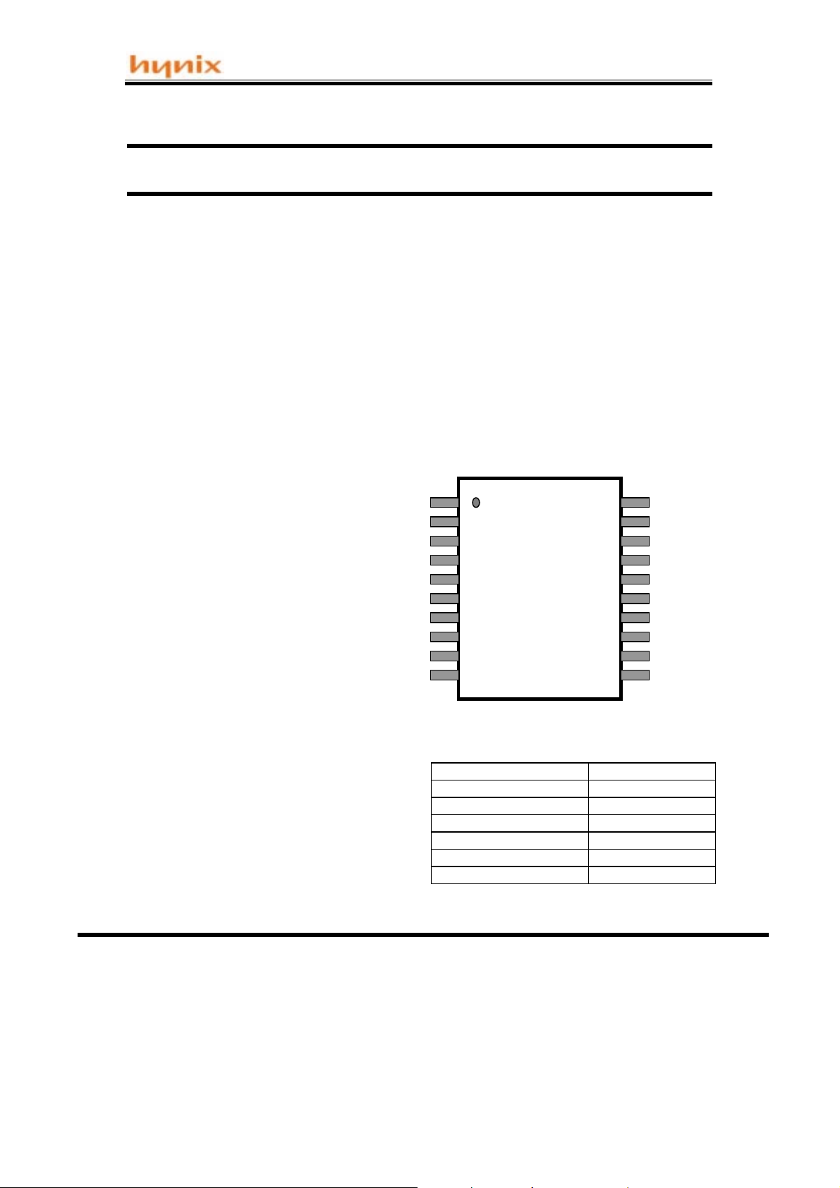
z 20 pins SOP package
Detail description of HMS91C7432 function and its application
TCP/IP protocol suite is the key to inter-net
access. Email; Home Page materials and all
the data traffic on the inter-net are carry out
by using the TCP/IP well defined format.
Time before HMS91C7432 exist, most internet connection were to be handled by the PC.
Hand held devices and equipments must be
attached to the PC to get access to the
inter-net. Now the era of “PC-free” inter-net
connection has come. With HMS91C7432,
you can make your product be able to send
and receive email; surf on the WWW and
even “TALK” to another device through the
inter-net, by just plugging the telephone line
onto it.
The core of the HMS91C7432 is a complete
TCP/IP protocol suite. Files and messages
pass to the HMS91C7432 will be transformed
into the appropriate format and packets to
conform the inter-net standard. This
transformation is transparent to the user’s
application.
On top of the TCP/IP core, there is an Email
engine built-in. User’s program just needed
to inform the HMS91C7432 an email is going
to send and follow with the email body.
HMS91C7432 will then wake up the modem
and dial the ISP to log on the mail server. The
mail will be sent when log on has success.
HMS91C7432 complete this whole process
fully automatic.
the server, then it check and download any
email automatically. Each message will be
stored in the RAM buffer, HMS91C7432 will
notify the application program an email has
come and waiting for retrieve.
The built-in PPP module handles the “Log on
process”. This is a standard protocol to pass
the user’s account ID and the password to
the ISP. This module handles the
authentication and “Handshaking”. User’s
program just pass the user’s ID and
password to HMS91C7432 and the PPP do it
all.
HMS91C7432 (later version only) also equip
with a FTP module to facilitate file transfer
and file downloading from the FTP site. This
function is especially good for remote system
update and game download for hand-held
game inter-net access.
The standard serial DTE interface on the
HMS91C7432 ease the modem connection.
The built-in modem driver support V.90 and
56K flex dual modem or lower.
HMS91C7432 is controlled by an 8 bit
data/command port. This port accepts
command passed by the host MCU.
Incoming and outgoing mess age will be
passed between the host and the
HMS91C7432 through this port as well.
Reception of Email is as simple as getting
email on the PC. The application program
send a “Receive Email” command to the
HMS91C7432, it dial up the ISP and log on
2
Page 3
Hynix semiconductor
Specifications of HMS91C7432
The HMS91C7432 TCP/IP communication controller is manufactured in advance CMOS
process.
The HMS91C7432 im plement complete TCP/I P protocol suite inc ludes PPP; IP; ICMP;T CP;
UDP; DNS; SMTP; POP3 protocol and additionally a general MODEM driver.
The HMS91C7432 is built-in with 96Kb SRAM (12K x 8) for communication and buffering, A full
duplex UART as DTE for ease of serial modem connection.
The HMS91C7432 has an 8 bits Data/Command port and 4 control pins to facilitate control and
communication between the Host MCU and the modem. There are only 20 simple commands,
each of which is a single byte long, to establish and to complete the whole internet
communication. 45 respond codes for the Host MCU to monitor the communication status.
Extremely low external component count. Very low power consumption.
Features :
D0
D1
y
Implement TCP/IP protocol suit.
y
SMTP for sending email
y
POP3 for receiving email
y
PPP for dialup network log on
and hand shaking.
y
DNS protocol to resolve IP
address from URL
y
Full static operation
y
Full Duplex 56K/115Kbps UART
port for modem DTE connection.
y
Speed range up to 22.118MHz
y
8 bits Bi-directional Data/Command bus.
y
Modem driver included
y
Power control modes
9
Active mode
9
Power-down mode
y
Dissipating Current
ß
Active 25mA
ß
Power-down 10uA max.
y
20 single byte easy commands
y
45 respond codes
Package type 20-SOP
y
y
D2
D3
D4
D5
D6
D7
Test
VCC
20
2
3
HMS91C7432
4
5
6
7
8
9
10
Operating voltage 3.3V +/- 10%
Dissipating Current
Active mode 25 mA
Power down mode 10uA max.
Oscillation Frequency 11.0592 Mhz
Operating Temperature
Storage Temperature
SOP 20
19
18
17
16
15
14
13
12
11
-40 to +85
-65 to +150°C
RXD
TXD
Reset
Strobe
WR
INT
Wait
Xtal 2
Xtal 1
Vss
°C
3
Page 4

Hynix semiconductor
Specifications of HMS91C7432
MNEMONIC PIN TYPE NAME AND FUNCTION
Vss 14
Vcc 9
D0 to D7 1 – 8 I/O
WAIT 14 Out
INT 15 Out
WR 16 In
STROBE 17 In
RXD 20 In
TXD 19 Out
RESET 13 In
TEST 10 In
XTAL 1 11 In
XTAL 2 12 Out
Ground :
Power Supply :
normal, and power-down operat io n.
Data/Command Port :
port with internal pull-ups . This port is for data transfer
between Host MCU, it also serves as command reception
and responds code iss uance port from and to the Host
MCU.
WAIT :
OK to start a cycle (assert a strobe), when high it
indicates that it is OK to end the cycle (de-assert a
strobe).
INT :
data/respond code are to be sent.
WRITE :
for a write cycle. Set this pin HIGH for a read cycle.
STROBE :
Data_Read or Data_Write operation is in process.
RXD :
TXD :
RESET :
oscillator is running resets the device.
TEST :
operation.
XTAL1 :
input to the internal clock generator circuits.
XTAL2 :
0V reference.
This is the power supply voltage for
This is an 8 bit bi-direc tional I/O
Handshake signal. W hen low it i ndicates that is
Active LOW Output a request to the Hos t MCU if
Active LOW write en ab le pin.
Data strobe signal.
UART serial input port.
UART serial output port.
A high level on this pin for 2us while the
Test pin, should be stuck at zero when norm al
Input to the inverting oscillator amplifier and
Output to the inverting oscillator amplifier.
Active low indicates a
Set this pin LOW
Table 1. Pin descript io ns
4
Page 5
Hynix semiconductor
Specifications of HMS91C7432
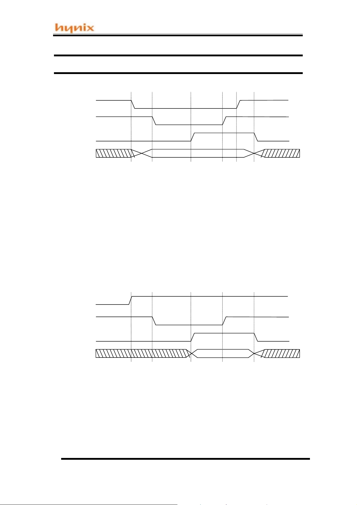
1 2 3 4 5 6
WR
Strobe
Wait
Data[7:0]
Figure 1. Data Write Cycle waveform
Data Write cycle phase transitions:
1. The Write line is asserted and the data is output to the parallel port
2. The data strobe is asserted, since WAIT is asserted low
3. The port waits for the acknowledge from the HMS91C7432 (WAIT de-asserted)
4. The data strobe is de-asserted
5. The write cycle ends
6. WAIT is asserted low to indicate that the next cycle may begin
Valid data
1 2 3 4 5
WR
Strobe
Wait
Data[7:0]
Figure 2. Data Read Cycle waveform
Data Read cycle phase transitions:
1. The Write line is set to HIGH to indicate read request
2. The data strobe is asserted, since WAIT is asserted low
3. The port waits for the acknowledge from the HMS91C7432 (WAIT de-asserted)
4. The data strobe is de-asserted after data is stored and the read cycle ends
5. WAIT is asserted low to indicate that the next cycle may begin
Valid data
5
Page 6

Hynix semiconductor
µ
µ
µ
Specifications of HMS91C7432
❏
DC Characteristics
(Ta = -20 To +85 , Vcc = 5V 10%, Vss = 0V)
SYMBOL
V
IL
V
IL1
V
IH
V
IH1
V
IH2
V
OL
V
OH
I
IL
PARAMETER
Input low voltage,except Reset
Input low voltage,Reset
Input high voltage,except Xtal1,Reset
Input high voltage,Xtal1
Input high voltage, Reset
Output low voltage,D0~D7,Strobe,
WR,INT,Wait
Output high voltage, D0~D7,Strobe,
WR,INT,Wait
Logical 0 input current, D0~D7,Strobe,
WR,INT,Wait
I
OL
I
OH
V
IN
TEST
= 3.5mA
= -25µA
= 0.45V
LIMITS
MIN MAXCONDITIONS
-0.5
-0.5
0.7Vcc
0.7Vcc
0.6Vcc
0.75Vcc
-10
0.2Vcc-0.1
0.2Vcc+0.1
Vcc+0.5
Vcc+0.5VV
Vcc+0.5 V
1.0 V
-50
UNIT
V
V
V
A
I
TL
I
CC
Logical 1-to-0 input current,
D0~D7,Strobe,WR,INT,Wait
Power supply current :
Active mode@11.0592MHz
V
= 3.0V
IN
Vcc = 5V
-65
Power-down mode @11.0592MHz
NOTES :
1. See Figure 3 through 5 for Icc test conditions. Minimum Vcc for power down is 2V.
2. Under steady state (non-tra nsient) conditions,I
Maximum I
Maximum I
Maximum total I
If I
OL
per port : 10mA
OL
per 8-bit port D0~D7,Strobe,WR,INT,Wait : 15mA
OL
for all output pins : 71mA
OL
exceeds the test condition,VOL may exceed the related specification.Pins are not
must be externally limited as follows :
OL
guara nteed to sink current greater than the listed test conditions.
-650
16
10
A
mA
A
6
Page 7

Hynix semiconductor
µ
µ
µ
Specifications of HMS91C7432
❏
DC Characteristics(Cont.)
(Ta = -20 To +85 , Vcc = 3.3V 10%, Vss = 0V)
SYMBOL
V
IL
V
IL1
V
IH
V
IH1
V
IH2
V
OL
V
OH
I
IL
PARAMETER
Input low voltage,except Reset
Input low voltage, Reset
Input high voltage,except Xtal1,Reset
Input high voltage,Xtal1
Input high voltage,Reset
Output low voltage,D0~D7,Strobe,
WR,INT,Wait
Output high voltage, D0~D7,Strobe,
WR,INT,Wait
Logical 0 input current, D0~D7,Strobe,
WR,INT,Wait
TEST
LIMITS
UNIT
MIN MAXCONDITIONS
-0.5
-0.5
0.7Vcc V
0.7Vcc V
0.6Vcc V
IOL= 1.6mA V
I
OH
V
IN
= -20µA
= 0.45V
2.7
-6
0.8
0.8
Vcc+0.3
Vcc+0.3
Vcc+0.3
0.45
-50
V
V
V
A
I
TL
I
CC
Logical 1-to-0 input current,
D0~D7,Strobe,WR,INT,Wait
Power supply current :
Active mode@11.0592
Power-down mode
= 2.0V
V
IN
Vcc = 3.3V
-40
-250
10
10
A
mA
A
7
Page 8
Hynix semiconductor
Specifications of HMS91C7432
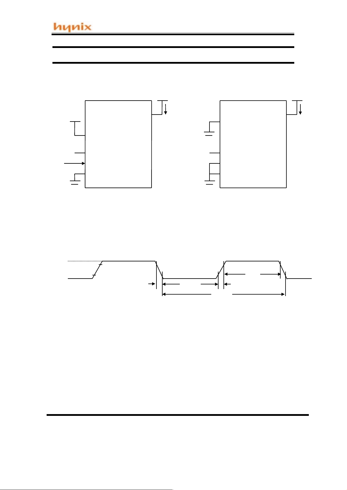
DC Characteristics(Cont.)
Vcc
Reset
(NC)
CLOCK
SIGNAL
All other pins are disconnected.
Figure 3. Icc Test Condition,Active Mode
Vcc-0.5
0. 5V
Xtal2
Xtal1
Vss
0.7Vcc
0.2Vcc-0.1
tCHCL
Vcc
Icc
Reset
(NC)
All other pins are disconnected.
Figure 4. Icc Test Condition,Power Down Mode
tCLCX tCLCH
Xtal2
Xtal1
Vss
tCHCX
Vcc
Icc
tCLCL
Figure 5. Clcok signal Wavefoerm for Icc Tests in Active Mode
tCLCH = tCHCL = 5ns
NOTES :
1. Icc(active mode) is meas ured with:
Xtal1 driven with tCLCH = tCHCL = 5ns, VIL = Vss + 0.5V, VIH = Vcc - 0.5V, X2 = N.C.
Reset = Vcc, all other pins are disconnected.
Icc would be slightly higher if a crystal oscillator is used (appr. 1mA)
2. Icc(power down mode) is measured with:
Xtal1 = Vss, Xtal2 = N.C., Reset = Vss, all other pins are disconnected.
8
Page 9

Hynix semiconductor
Specifications of HMS91C7432
AC ELECTRICAL CHARACTERISTICS
(Ta = -2 0oC To +85oC, Vcc = 5.0V + 10%, 3.3V + 10%, Vss = 0V)
EXTERNAL CLOCK DRIVE
5.0V +/- 10% 3.3V +/- 10%
Symbol Parameter
Min Max Min Max
Unit
1/t
CLCL
t
CHCX
t
CLCX
t
CLCH
t
CHCL
Osc. Feq.
High Time
Low Time
Rise Time
Fall Time
3.5
20
20
25
20
20
EXTERNAL CLOCK DRIVE WAVEFORM
Vcc-
0.7V
0.45
0.2Vcc-
t
CHCL
t
CLCX
3.5
15
15
t
CLCL
t
CLCH
20
t
CHCX
25
25
MHz
ns
ns
ns
ns
9
Page 10

Hynix semiconductor
Specifications of HMS91C7432
Data format for communication between HMS91C7432 and the host MCU
Sync 1
0x7E
Sync 2
0xFE
Contro
l code
DataIDData
flag
Length Data 0
ReservedData 0
Figure 3. Data packet format
Max 131 bytes for data
Max 128 bytes for data
Data 130
Data
127
Field description :
Field Description Value
Sync 1 Synconization for start of Command/Data packet. Always set to 0x7E
Sync 2 As above Always set to 0xFE
Control code This is the command code field in sim ple command
mode. Specify the “Type of command” in complex
command mode.
Length Specify the length of the Data field. 0 ~ 131
Data f ields Max. lengt h of 131 octets for each packet containing
structures for complex command data; setup
parameters; reponse code and mail text contents in
various communication mode accordingly.
Data ID Specify the types of data containing in the current
packet.
Data Flag Specify whether the current packet is the last packet or
more packet follow.
Reserved Reserved for test purpose. Disregard this field in
normal operation.
Data 0 ~ 127 Contain max 128 octets of data Single byte data
In simple command
mode 0x80 ~ 0x89.
In complex command
mode 0x00 ~ 0x06
Refer to table 3
Refer to the explaination
of the communication
mode.
0x00 ~ 0x34
refer to the table 4
0x00 more packet follow
0x01 last packet
Not applicable
Table 2. Field descriptions for communication packet
10
Page 11

Hynix semiconductor
Specifications of HMS91C7432
Table 3. Listing of Control Code
Control
Description Direction
Code
0x00 Use this control code for complex comm and mode and mail text
transfer. This is a bi-directional command code. HMS91C7432
uses this code to pass mail’s inform ation and mail’s bod y to the
host.
0x01 For HMS91C7432 to issue complex command to the host to
request for Line Connection Info (refer to Table 5 for Info Listing).
0x02 For HMS91C7432 to issue Result Code to the host (refer to Table
6 for Result Code Listing).
0x03 For HMS91C7432 to issue the Connection Status to the host
(refer to Table 7 f or Connection Status Listing). The issu ance of
the Connection Status is in respond to the Host’s re quest using
Control Code 0x04 in the complex command mode.
0x04 Host use this control code to request the report for Connection
Status. This code is to be used in Simple Command mode.
0x05 Host use this control code to request the report for SMTP
Processing Status. T his code is to be used in Sim ple Comm and
Mode.
0x06 For HMS 91C7432 to issue the SMTP Processing Stat us ( r ef er to
Table 8 for the SMT P Stat us Listing). T he iss uance of the S MTP
Processing Status is in respond to the Host’s request using
Control Code 0x05 in the complex command mode.
0x80
0x81
0x82
Initiate Modem
Instruct the HMS91C7432 to initialize the Modem and send the
pre-set AT initializing string. This com mand mus t be issued after
the AT initializing string has been passed.
Terminate
the HMS91C7432 to terminate the current process.
Log In ISP –
the HMS91C7432 to Login to the ISP. When the command is
accepted, HMS91C7432 will run the login proc ess automaticall y
and report to the host by using Control Code 0x02 complex
command. The whole login process consists of the following
steps, and Connection Status will be reported on each step.
1. Modem off hook
2. Dial up ISP
3. Modem handshake
4. Logon and authentication check using PPP
The Login process ends when the authentication check is passed
or in any cases a connection failure occurs.
– host’s command in Sim ple Command mode.
– host’s command in Simple Command mode. Instruct
host’s command in Simple Command mode. Instruct
Bi-directional
depending on
the Data ID
HMS91C7432
To Host
HMS91C7432
To Host
HMS91C7432
To Host
Host to
HMS91C7432
Host to
HMS91C7432
HMS91C7432
To Host
Host to
HMS91C7432
Host to
HMS91C7432
Host to
HMS91C7432
This command m ust be issued after the Login i nformation have
been passed, other wise, HMS91C7432 will issue requ est using
Control Code 0x01 for missing info.
11
Page 12

Hynix semiconductor
Specifications of HMS91C7432
Continue of Table 3. Listing of Control Code
0x83
0x84
0x85
0x86
Quit ISP
the HMS91C7432 to end the current ISP session. When the
command is accepted, HMS91C7432 will run the Disconnect
process automatically and report to the host by using Control
Code 0x02 complex command. The whole Disconnect process
consists of the following steps, and Connection Status will be
reported on each step.
The Quit process ends when the modem responds with On Hook
OK, or in any cases a connection failure occurs.
Login SMTP Server
mode. Instruct the HMS91C 7432 to lo gin to t he ded icate d SMT P
server. Upon the command is accepted, HMS91C7432 will run the
following steps, and Conn ection Status will be repor ted on each
step.
The Login SMTP process ends when the SMTP server returns an
OK response code, or in any cases a Logon failure occurs.
Quit SMTP Server
Instruct the HMS91C7432 to end the current SMTP session. Upon
the command is accepted, HMS91C7432 will quit the SMTP
Server and keep ON LINE (keep connection with the internet).
Quit SMTP OK will be reported to the host by using Control Code
0x02 complex command.
Send Mail Request
mode. Instruct the HMS91C7432 to get permission from the
SMTP server for send ing mail. Upon the c ommand is acc epted,
HMS91C7432 will run the following steps, and Connection Status
will be reported on each step.
When the SMTP server accept all the mail info and an OK to send
is received, HMS91C7432 will issue Ready to send response
using Control Code 0x02 to the host. DO NOT send the mail body
before this response is issued.
– Host’s comm and in Sim ple Comm and mode. Instruct
1. Quit the ISP internet connection
2. Disconnect the telephone line
3. Hang up the modem and modem go On Hook
- Host’s command in Simple Command
1. Run DNS protocol to resol ve for the S MTP server’s IP
address.
2. Register to the SMTP server.
- Host’s command in Simple Command mode.
- Host’s command in Simple Command
1. Send the “Send Mail” request to the SMTP server
2. Pass Sender em ail address; Recipien t email address
to the SMTP server for validation.
3. Wait for permission to send the mail’s body.
Host to
HMS91C7432
Host to
HMS91C7432
Host to
HMS91C7432
Host to
HMS91C7432
12
Page 13

Hynix semiconductor
Specifications of HMS91C7432
Continue of Table 3. Listing of Control Code
0x87
Login POP3 server
mode. Instruct the HMS 91C7432 to login to t he ded icated PO P3
server. Upon the command is accepted, HMS91C7432 will run the
following steps, and Conn ection Status will be repor ted on each
step.
1. Run DNS protocol to resol ve for the PO P3 s erver’s IP
address.
2. Register to the POP3 server and run the authentication
check process
3. If authentication check is passed, request the POP3
server to return the number of mail contain in the
mailbox.
4. If UIDL option is set (refer to Table 4 for explanation of
UIDL option), request t he POP3 server to return the
Length and UID for each mail in the mailbox.
The Login POP3 process ends when the POP3 server returns the
number of mail and or th e UIDL, or in an y cases a Logon failure
occurs. Upon receipt of the “Num ber of Mail” info and the UIDL
info, HMS91C7432 will pass these info to the host by using
Complex Command mode with Control Code 0x00.
The Login POP3 command must be issued after the POP3 Login
information have been passed, otherwise, HMS91C7432 will
issue request using Control Code 0x01 for missing info.
- Host’s command in Simple Command
Host to
HMS91C7432
0x88
0x89
Quit POP3 Server
Instruct the HMS91C7432 to end the current POP3 session. Upon
the command is accepted, HMS91C7432 will quit the POP3
Server and keep ON LINE (keep connection with the internet).
Quit POP3 OK will be reported to the host by using Control Code
0x02 complex command.
Shut Down HMS91C7432
Command mode. Instruct the HM S91C7432 to enter the Power
Down mode. Make sure the SMTP session or the POP3 session is
terminated and the line is disconnected before the Shut Down
command is issued.
- Host’s command in Simple Command mode.
- Host’s command in Simple
Host to
HMS91C7432
Host to
HMS91C7432
13
Page 14

Hynix semiconductor
Specifications of HMS91C7432
Table 4. Listing of Data ID
Data ID Description Command mode
0x00 Baud rate for HMS91C7432 serial UART port setting. Host command
0x01 Modem AT initialize string “”
0x02 Modem Result Code listing “”
0x03 HMS91C7432 clock selection “”
0x04 POP3 UIDL return option “”
0x05~0x20 Reserved by the system. Do Not Use. “”
0x21 Telephone Number for dialup network. “”
0x22 User ID for the dialup network account “”
0x23 Password for the dialup network account “”
0x24 IP address for the DNS server (if not specified, dynam ic DNS
server search will be used).
0x25 SMTP port (if not specified, use default value port 25) “”
0x26 POP3 port (if not specified, use default value port 110) “”
0x27 SMTP server domain name “”
0x28 POP3 server domain name “”
0x29 User ID for POP3 account “”
0x2A Password for POP3 account “”
0x2B Sender’s email address “”
0x2C Recipient’s email address “”
0x2D Mail text body Host command /
0x2E Reserved N.A
0x2F Reserved N.A.
0x30 Number of mail in POP3 server HMS91C7432
0x31 UID listing HMS91C7432
0x32 Get Mail (followed with the mail number) Host command
0x33 Delete Mail from server (followed with the mail number) Host command
0x34 Get UID for a particular m ail on the server (followed with the
mail number)
Host command
“”
HMS91C7432
data returns
returns
returns
14
Page 15

Hynix semiconductor
Specifications of HMS91C7432
Table 5. Listing of Info code for complex request mode made by HMS91C7432
Data ID Description
Data_ID.0 Requesting Recipient’s and Sender’s email address
Data_ID.1 Requesting Password for POP3 account
Data_ID.2 Requesting User ID for POP3 account
Data_ID.3 Requesting Domain Name for POP3 server
Data_ID.4 Requesting Domain Name for SMTP server
Data_ID.5 Requesting Password for dialup network account
Data_ID.6 Requesting User ID for dialup network account
Data_ID.7 Requesting Telephone number for dialup account
Note on use: Whenever the HMS91C74 32 needs net work connection inf o, and it is miss ing or
corrupted in HMS91C7432 memory, HMS91C7432 will issue a request using complex
command mode with Control Code 0x01 following with the above Data ID for necessary
information return. Each bit of the Data ID, if set, indicates the co-responding info is needed.
Table 6. Listing of Response Code issued by HMS91C7432
In respond to the host ’s command, the HMS91C7432 always return the following Res ponse
Code by using complex command mode with Control Code 0x02. The time taking to a response
is variable and mostly depending on the physical connection and the network traffic. Make sure
a response code is received before issuing a new command.
Response
Code
0x40
0x41
0x42
0x43
0x44
0x45
0x46
0x47
0x48
0x49
Modem is ready
Connected –
Modem not ready
not return a correct response
No Carrier
up automatically.
Error
– Modem internal error or unknown modem error.
No Dial tone
line is not connected.
Busy –
No answer
Modem Hang Up
Internet Logon OK –
passed, Logon success.
modem is connected to the remote terminal
– No carrier signal is detected. Modem will hang
– No dial tone is detected. Possibl y the phone
Line is busy.
– phone is no answer
Description Related layer and
Modem initialization
Modem Dialup
– modem is not presented or modem does
– The modem is disconnected.
The internet acc ount auth ent icatio n is
Modem initialization
Modem Dialup
Modem Dialup
Modem Dialup
Modem Dialup
Modem Dialup
Modem Dialup
PPP
protocol
15
Page 16

Hynix semiconductor
Specifications of HMS91C7432
Continue to Table 6. Listing of Response Code issued by HMS91C7432
0x4A
0x4B
0x4C
0x4D
0x4E Reserved
0x4F Reser ved
0x50
0X51
0x52
0x53
0x54
0x55
0x56
0x57
0x58
0x59
0x5A
0x5B
0x5C
0x5D
0x5E
0x5F
0x60
0x61
0x62
ISP No Response
out.
Authentication Fail –
Logon Fail –
Internet Quit OK
Line.
Mail Sent OK
SMTP Logon Fail
Mail Received OK
POP3 Logon Fail
POP3 Authentication Fail
POP3 password
Transmission Data Error
accepted (e.g. un-resolvable email address)
Reception Data Error
NO New Mail
SMTP Logon OK
POP3 Logon OK –
DNS Fail
invalid data
SMTP Quit
POP3 Quit –
Mail Deleted –
Mail Deleted Fail
number is not exist or the mail is locked by the server
Wrong Mail Number
mailbox.
SMTP Ready to Send
next packet of the mail text body.
SMTP Buffer Overflow
full. Last packet received is invalid. Host must resend the
previous packet.
SMTP Buffer full –
full and can not accept more data. The last packet is
accepted.
– ISP has no response after a long time
Invalid User ID or invalid password
Unable to logon to the internet for other reason
– Disconnect fr om the internet an d go Off
– a mail is sent successfully
– Fail to logon to the SMTP server
– A mail is received successfully
– Fail to logon to the POP3 server
– Invalid POP3 User ID or invalid
– Data passed to the server is not
– Invalid data is received.
– POP3 mail box is empty
– Successfully Logon to the SMTP server
Successfully Logon to the POP3 server
– Unable to locate DNS server or DNS server return
– Exit SMTP server
Exit POP3 server
A mail is deleted from the POP3 mail box
– Unable to delete the mail, either the mail
– The mail number not exist in the
– HMS91C7432 is re ady to accept
– HMS91C7432 outgoing b uffer is
HMS91C7432 outgoing buff er is nearly
PPP
PPP
PPP
PPP
SMTP
SMTP
POP3
POP3
POP3
SMTP
POP3
POP3
SMTP
POP3
DNS
SMTP
POP3
POP3
POP3
POP3
SMTP
SMTP
SMTP
16
Page 17

Hynix semiconductor
Specifications of HMS91C7432
Table 7. List of Response Code for Network Status
Upon receipt of a “Net work Status Request” iss ued by the host with Contr ol Code 0x04, the
HMS91C7432 respond th e request by returning t he following code using complex command
mode with Control Code 0x03.
Response
Code
0x00
0x01
0x02
0x03
0x04
0x05
0x06
0x07
0x08
0x09
0x0A
0x0B
0x0C
0x0D
0x0E
0x0F
0x10
0x11
Mnemonics Descriptions
Wait
Dialing
Logon ISP in progress
Logon ISP OK
Logon SMTP in progress
Logon SMTP OK
Mail Header is accepted
Sending Mail
Quitting SMTP server
Logon POP3 in progress
Logon POP3 Ok
Getting Uid
Requesting Mail
Retrieving Mail
Deleting Mail
Quitting POP3 server
Network disconnecting
Modem disconnecting
Network is on hold or in processing, waiting for the
network to return instruction or data.
HMS91C7432 is connecting the internet service.
Passing Logon info and authentication check in
progress
System is On Line and the network is connected.
Resolving SMTP IP address and waiting for SMTP
server to respond.
System has logon to the SMTP server. Ready to send
mail (send the mail header for validation first).
SMTP server has validated the addresses
Sending Mail in progress
Quit command has been is sued to the SMT P server,
waiting for response.
Resolving POP3 server ’s IP address and wait ing for
the result of the authentication check.
System has logon to the POP3 server.
Waiting for return of Unique ID of a mail.
Mail request was sent, waiting for server to return
mail.
Mail reception in progress.
Delete Mail request was sent, waiting for server to
return result.
Quit command has been issued to the PO P3 server,
waiting for response.
Quit command has been issued to the ISP, waiting for
server to respond.
Hanging up the modem and waiting for the modem to
respond.
17
Page 18

Hynix semiconductor
Specifications of HMS91C7432
Table 8. List of SMTP status response
HMS91C7432 return the following response code when the host makes a
request by using simple co mmand mode wi th control code 0x 05. HMS91C7 432
return the response by using complex command mode with control code 0x06.
Response
code
0x60
0x61
0x62
Mnemonics Description
SMTP Ready to Send
SMTP Buffer Overflow
SMTP Buffer full
HMS91C7432 is read y to acc ept nex t pack et of the m ail
text body.
HMS91C7432 outgoing buffer is full. Last packet
received is invalid. Host must resend the previous packet.
HMS91C7432 outgoing buff er is nearly full and can n ot
accept more data. The last packet is accepted.
Examples of inter-chip communication session:
Example 1. Commands issued by the host using Simple Command Mode
Sync 1 Sync 2 Control code Length
0x7E 0xFE 0x80 ~ 0x89 0x00
The following command string instructs the HMS91C7432 to logon to the ISP
0x7E 0xFE 0x82 0x00
Example 2. Command issued by the host that using Complex Command Mode
Sync 1 Sync 2 Control Leng th Data I D Data Flag Reserved Data 0 ………….... Data 127
0x7E 0xFE 0x00 Value 0 ~ 34h 0 or 1 NA
The following command string instructs the HM S91 C7432 to retrieve a the mail #2 from the
POP3 server. Note that the Mail number must be defined as an integer (2 bytes long).
Sync 1 Sync 2 Control Length Data ID Data Flag Reserved Data 0 Data 1
0x7E 0xFE 0x00 0x05 0x32 0x01 0x00 0x00 0x 02
Example 3. A packet of mail text body received from HMS91C7432
This packet is pas sed from the HMS91C7432 in Complex Data Mode, Data ID 0x2D indicate
that the packet contain portion of a mail body. Data Flag is ‘0’ indicates th at more packet will
follow. Length is ‘0x83’ ind ic ates th at t her e are 13 1 bytes after the length field. The actual text
data occupy 128 bytes only. Use the same format to pass outgoing mail body to the
HMS91C7432.
Sync 1 Sync 2 Control Length Data ID Data Flag Reserved Data 0 Data 1 …….. Data 127
0x7E 0xFE 0x00 0x83 0x2D 0 0 T e Ascii x
18
Page 19

Hynix semiconductor
Specifications of HMS91C7432
Example 4. HMS91C7432 request for missing connection info
When the HMS91C7432 is going to make a connection to the internet or to a mail server, it will
check if all nec essary info is available. T he connection info may be erase d due to memory
overlaying. Upon an internet sess ion is ended, HMS91C7432 will clear its memory pool for
another session. Whenever connection info is needed, HMS91C7432 will issue a request to the
host for such info. The r equest will be m ade us ing com plex com m and mode with contr ol cod e
0x01 followed by a Data ID as listed in Table 5.
Sync 1 Sync 2 Control Length Data ID
0x7E 0xFE 0x01 0x01 0x08
This example demostrates a request made by the HMS91C7432 for the POP3 server’s domain
name when it is going to logon to the POP3 server.
Example 5. HMS91C7432 returning result code to the host
There are sets of Result Code coresponding to each command issued by the host to the
HMS91C7432. The HMS91C7432 returns at least one result code to each command, to report
the result of execution or the status of the connection. HMS91C7432 returns the result code by
using complex command mode with control code 0x02 followed by the result code (in the Data
ID field) as listed in Table 6.
Sync 1 Sync 2 Control Length Data ID
0x7E 0xFE 0x02 0x01 0x49
This example demonstrates a result code returned from HMS91C7432 to report that the
authentication check is passed and the system is ON LINE (Logon to the ISP is success).
Example 6. Host requesting Connection Status and the HMS91C7432 returns
User may make a request for the connection status at any time during the internet session. The
host may make its request b y using Simple Command Mode with Control Code 0x04. The
HMS91C7432 will return the connection status by Complex Command Mode with Control Code
0x03 followed by the connection status code as listed in Table 7.
This example demonstrates how the host m akes a connection status request and how the
HMS91C7432 responds to this request. The host made the request after a successful logon to
the POP3 server. The HMS91C7432 report that the system has logon to the POP3 server.
Host requesting command format:
Sync 1 Sync 2 Control Length
0x7E 0xFE 0x04 0x00
HMS91C7432 return the connection status:
Sync 1 Sync 2 Control Length Data ID
0x7E 0xFE 0x03 0x01 0x0A
19
Page 20

Hynix semiconductor
Specifications of HMS91C7432
Example 7. Host requesting SMTP Connection Status and the HMS91C7432 returns
When sending out an email d urin g SMT P session, t he hos t should know when can it p ass the
mail header and when can it pass the mail body to the HMS91C7432. Usually , depending on the
traffic of the network, it tak es a longer tim e to be success fully logon to th e SMTP server. The
host should frequently check the connection status to determine the time to pass the mail
header or to determ ine when to term inate the logo n process if a t ime out is u p. The host m ay
make such a report by using Simple Command Mode with Control Code 0x05. The
HMS91C7432 will return the SMTP connection status by Complex Command Mode with Control
Code 0x06 followed with the SMTP status code as listed in Table 8.
This example dem onstrates ho w the host m akes a SMTP c onnection st atus req uest and h ow
the HMS91C7432 responds to this request. The host made the request after a successful logon
to the SMTP server. The HMS91C7432 report that it is read y to accept the mail body. If the
request is made during the mail sending session, the f ollo win g c on nec ti on status ind ic at es the
HMS91C7432 is ready to accept more packets (Outgoing buffer is not full).
Host requesting command format:
Sync 1 Sync 2 Control Length
0x7E 0xFE 0x05 0x00
HMS91C7432 return the connection status:
Sync 1 Sync 2 Control Length Data ID
0x7E 0xFE 0x06 0x01 0x 60
20
Page 21

Hynix semiconductor
Specifications of HMS91C7432
Plastic Package P-DIP-20
(Plastic Dual In Package)
* 1.043
1.010
* 1.043
1.010
0.180MAX
0.021
0.015
0.065
0.050
0.014
0.300BSC.
0.008
0
~
0.100 PITCH
0.140
0.120
**0.270
0.245
0.015MIN
UNIT : INCH
**0.270
0.245
- NOTE -
1. DIMENSION * MARK DOES NOT INCLUDE MOLD
PROTRUSION
MAXIMUM ALLOWABLE PROTRUSION IS 0.010 INCH
PER SIDE.
2. DIMENSION ** MARK DOES NOT INCLUDE MOLD
21
Page 22

Hynix semiconductor
Specifications of HMS91C7432
Plasti c Packag e P-SOP-20
(Plastic Small Outline Package)
* 0.5118
0.4961
UNIT : INCH
0.104
0.093
0.0118
0.004
* *0.299
0.291
* 0.5118
0.4961
0.050 PITCH
0.0125
0.0091
**0.299
0.291
0.020
0.013
0.419
0.398
0.042
0.016
- NOTE -
1. DIMENSION * MARK DOES NOT INCLUDE MOLD PROTRUSION
MAXIMUM ALLOWABLE PROTRUSION IS 0.006 INCH PER SIDE.
2. DIMENSION ** MARK DOES NOT INCLUDE MOLD PROTRUSION
MAXIMUM ALLOWABLE PROTRUSION IS 0.010 INCH PER SIDE.
3. DIMENSIONING AND TOLERANCING PER ANSI Y14.5M-1982
22
Page 23

Hynix semiconductor
Application examples
+06<4&:
Host MCU
for
embedded
application
0RGHP
765
(0$,/
&+,3
LCD panel
Keyboard
RAM
EEPROM
An example block diagram for a Data Bank Email Composer
+06<4&:
0RGHP
765
(0$,/
&+,3
Host MCU
for home
appliance
control
LCD panel
Keyboard
Fan motor
Heater
cooler
23
Page 24

Hynix semiconductor
+06<4&:
765
(0$,/
&+,3
Host MCU
for
embedded
application
RAM
6SHDNHU
3KRQH
0RGHP
An example block diagram for an Email Phone
Multiplexer
LCD panel
Keyboard
EEPROM
24
 Loading...