

Page 1
查询HMC322LP4供应商
14
MICROWAVE CORPORATION
v03.0604
GaAs MMIC SP8T NON-REFLECTIVE
Typical Applications
This switch is suitable for usage in DC - 8.0 GHz
50-Ohm or 75-Ohm systems:
• Broadband
• Fiber Optics
• Switched Filter Banks
• Wireless below 8 GHz
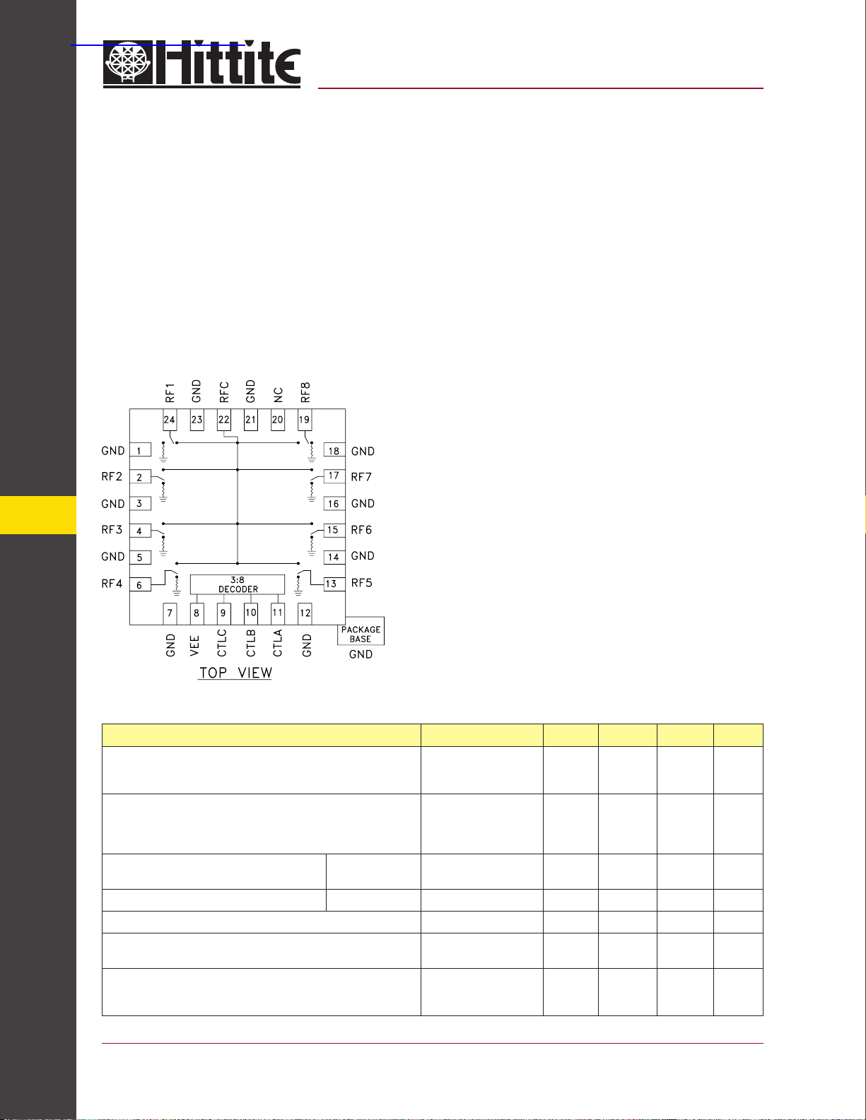
Functional Diagram
HMC322LP4
SWITCH, DC - 8.0 GHz
Features
Broadband Performance: DC - 8.0 GHz
High Isolation: >30 dB@ 6 GHz
Low Insertion Loss: 2.4 dB@ 6 GHz
Integrated 3:8 TTL Decoder
4 mm x 4 mm x 1 mm SMT Package
General Description
The HMC322LP4 is a broadband non-refl ective
GaAs MESFET SP8T switch in a low cost leadless surface mount package. Covering DC to 8
GHz, this switch offers high isolation and low
insertion loss. This switch also includes an on
board binary decoder circuit which reduces the
required logic control lines to three. The switch
operates using a negative control voltage of 0/-5
volts, and requires a fi xed bias of -5v. This switch
is suitable for usage in 50-Ohm or 75-Ohm systems.
Electrical Specifi cations, T
Insertion Loss
SWITCHES - SMT
Isolation
Return Loss “On State”
Return Loss “Off State” DC - 8.0 GHz 7 10 dB
Input Power for 1 dB Compression 0.5 - 8.0 GHz 19 23 dBm
Input Third Order Intercept
(Two-Tone Input Power = +7 dBm Each Tone)
Switching Characteristics
tRISE, tFALL (10/90% RF)
tON, tOFF (50% CTL to 10/90% RF)
14 - 176
= +25° C, With 0/-5V Control, 50 Ohm System
A
Parameter Frequency Min. Typ. Max. Units
DC - 2.0 GHz
DC - 4.0 GHz
DC - 8.0 GHz
DC - 2.0 GHz
DC - 4.0 GHz
DC - 6.0 GHz
DC - 8.0 GHz
DC - 2.0 GHz
DC - 8.0 GHz
0.5 - 8.0 GHz 36 40 dBm
DC - 8.0 GHz
35
30
25
20
9
6
2.1
2.3
2.5
40
35
30
25
12
10
50
150
For price, delivery, and to place orders, please contact Hittite Microwave Corporation:
12 Elizabeth Drive, Chelmsford, MA 01824 Phone: 978-250-3343 Fax: 978-250-3373
Order Online at www.hittite.com
2.5
2.7
2.9
dB
dB
dB
dB
dB
dB
dB
dB
dB
ns
ns
Page 2
v03.0604
HMC322LP4
MICROWAVE CORPORATION
GaAs MMIC SP8T NON-REFLECTIVE
SWITCH, DC - 8.0 GHz
GaAs MMIC SUB-HARMONICALLY PUMPED MIXER 17 - 25 GHz
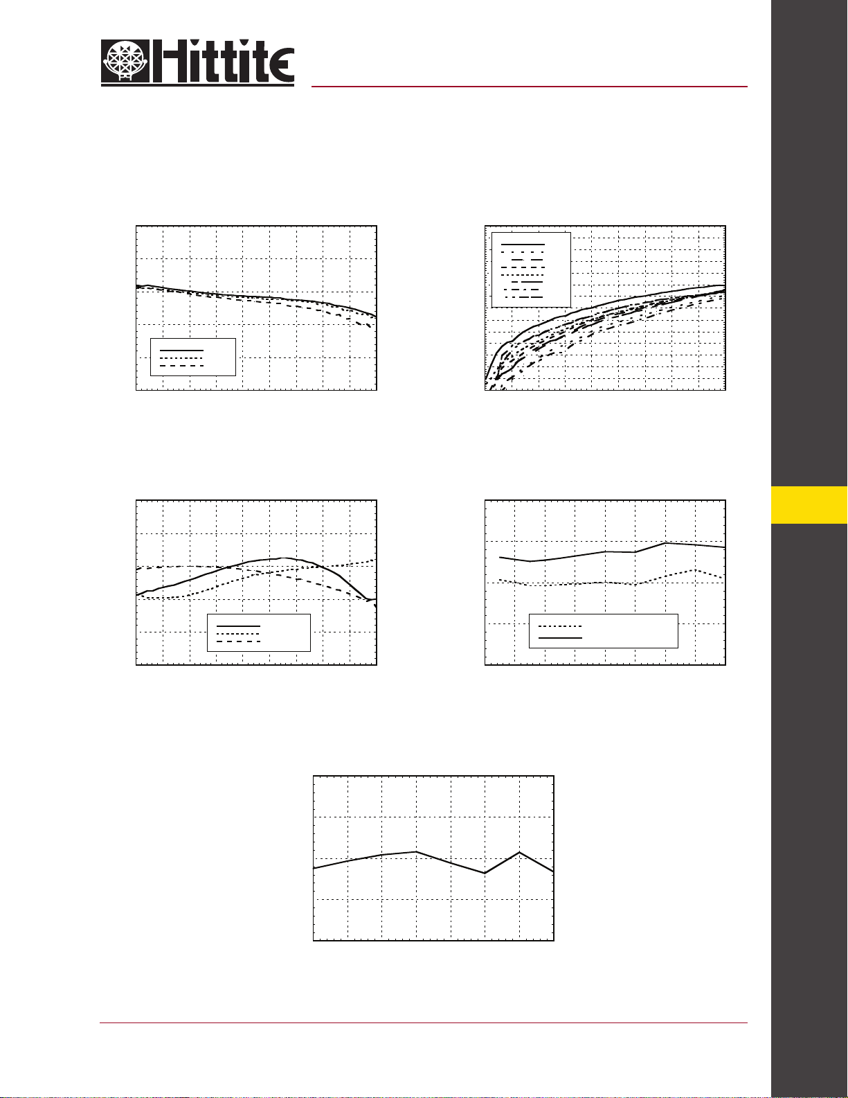
Insertion Loss vs. Temperature Isolation
0
-1
-2
-3
INSERTION LOSS (dB)
-4
-5
0123456789
+25 C
-40 C
+85 C
FREQUENCY (GHz)
0
-10
-20
-30
-40
ISOLATION (dB)
-50
-60
-70
0123456789
RF1
RF2
RF3
RF4
RF5
RF6
RF7
RF8
FREQUENCY (GHz)
Return Loss 0.1 and 1 dB Input Compression Point
0
-5
-10
-15
RETURN LOSS (dB)
-20
-25
0123456789
FREQUENCY (GHz)
RFC
RF1-8 ON
RF1-8 OFF
30
25
20
15
INPUT COMPRESSION POINT (dBm)
10
012345678
0.1dB Compression Point
1dB Compression Point
FREQUENCY (GHz)
14
Input Third Order Intercept Point
50
45
40
35
30
INPUT THIRD ORDER INTERCEPT (dBm)
12345678
FREQUENCY (GHz)
For price, delivery, and to place orders, please contact Hittite Microwave Corporation:
12 Elizabeth Drive, Chelmsford, MA 01824 Phone: 978-250-3343 Fax: 978-250-3373
Order Online at www.hittite.com
SWITCHES - SMT
14 - 177
Page 3
MICROWAVE CORPORATION
v03.0604
HMC322LP4
GaAs MMIC SP8T NON-REFLECTIVE
SWITCH, DC - 8.0 GHz
14
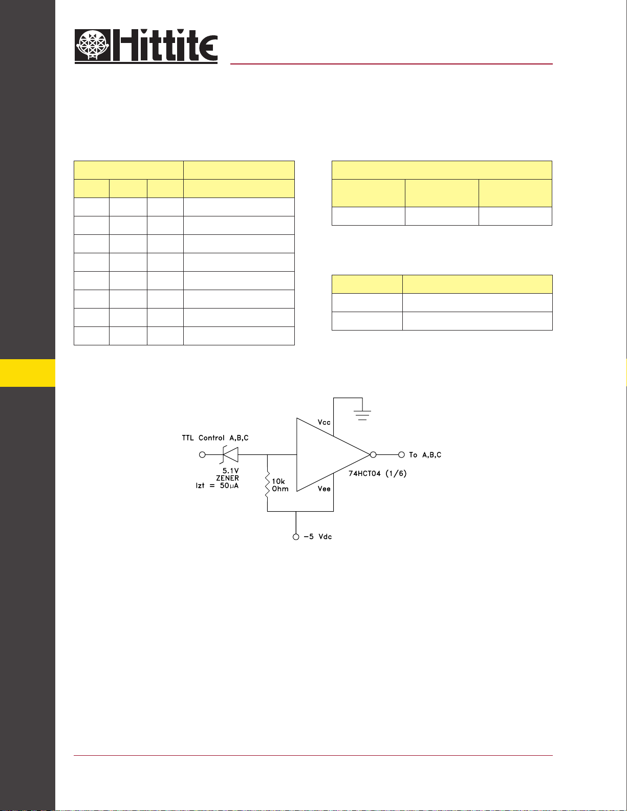
Truth Table
Control Input Signal Path State
A B C RFCOM to:
High High High RF1
Low High High RF2
High Low High RF3
Low Low High RF4
High High Low RF5
Low High Low RF6
High Low Low RF7
Low Low Low RF8
TTL Interface Circuit
Bias Voltage & Current
Vee Range = -5.0 Vdc ± 10%
Vee
(Vdc)
-5.0 5.0 9.0
Iee (Typ.)
(mA)
Control Voltages
State Bias Condition
Low -3V to 0 Vdc @ 25 uA Typical
High -5 to -4.2 Vdc @ 5 uA Typical
Iee (Max.)
(mA)
SWITCHES - SMT
Note:
Control inputs A, B, and C can be driven directly with TTL logic with -5 Volts applied to the HCT logic gates Vee pin and
to Vee (pin 8) of the RF Switch.
14 - 178
For price, delivery, and to place orders, please contact Hittite Microwave Corporation:
12 Elizabeth Drive, Chelmsford, MA 01824 Phone: 978-250-3343 Fax: 978-250-3373
Order Online at www.hittite.com
Page 4
MICROWAVE CORPORATION
v03.0604
Absolute Maximum Ratings
Bias Voltage Range (Vee) -7.0 Vdc
HMC322LP4
GaAs MMIC SP8T NON-REFLECTIVE
SWITCH, DC - 8.0 GHz
Control Voltage Range
(A, B, & C)
Storage Temperature -65 to +150 °C
Operating Temperature -40 to +85 °C
Maximum Input Power 26 dBm
Vee -0.5V to +1.0 Vdc
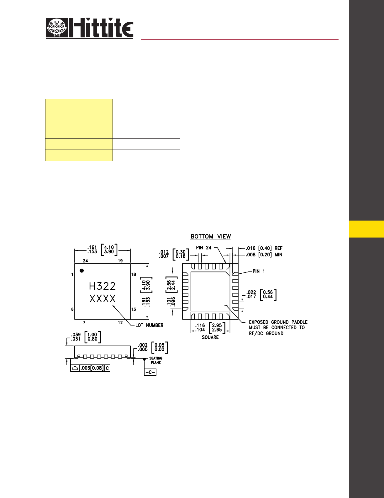
Outline Drawing
14
NOTES:
1. MATERIAL PACKAGE BODY: LOW STRESS INJECTION MOLDED
PLASTIC SILICA AND SILICON IMPREGNATED.
2. LEAD AND GROUND PADDLE MATERIAL: COPPER ALLOY
3. LEAD AND GROUND PADDLE PLATING: Sn/Pb SOLDER
4. DIMENSIONS ARE IN INCHES [MILLIMETERS].
5. LEAD SPACING TOLERANCE IS NON-CUMULATIVE
6. PAD BURR LENGTH SHALL BE 0.15mm MAXIMUM.
PAD BURR HEIGHT SHALL BE 0.05mm MAXIMUM.
7. PACKAGE WARP SHALL NOT EXCEED 0.05mm.
8. ALL GROUND LEADS AND GROUND PADDLE MUST BE SOLDERED
TO PCB RF GROUND.
9. REFER TO HITTITE APPLICATION NOTE FOR SUGGESTED PCB
LAND PATTERN.
For price, delivery, and to place orders, please contact Hittite Microwave Corporation:
12 Elizabeth Drive, Chelmsford, MA 01824 Phone: 978-250-3343 Fax: 978-250-3373
Order Online at www.hittite.com
SWITCHES - SMT
14 - 179
Page 5
MICROWAVE CORPORATION
v03.0604
HMC322LP4
GaAs MMIC SP8T NON-REFLECTIVE
SWITCH, DC - 8.0 GHz
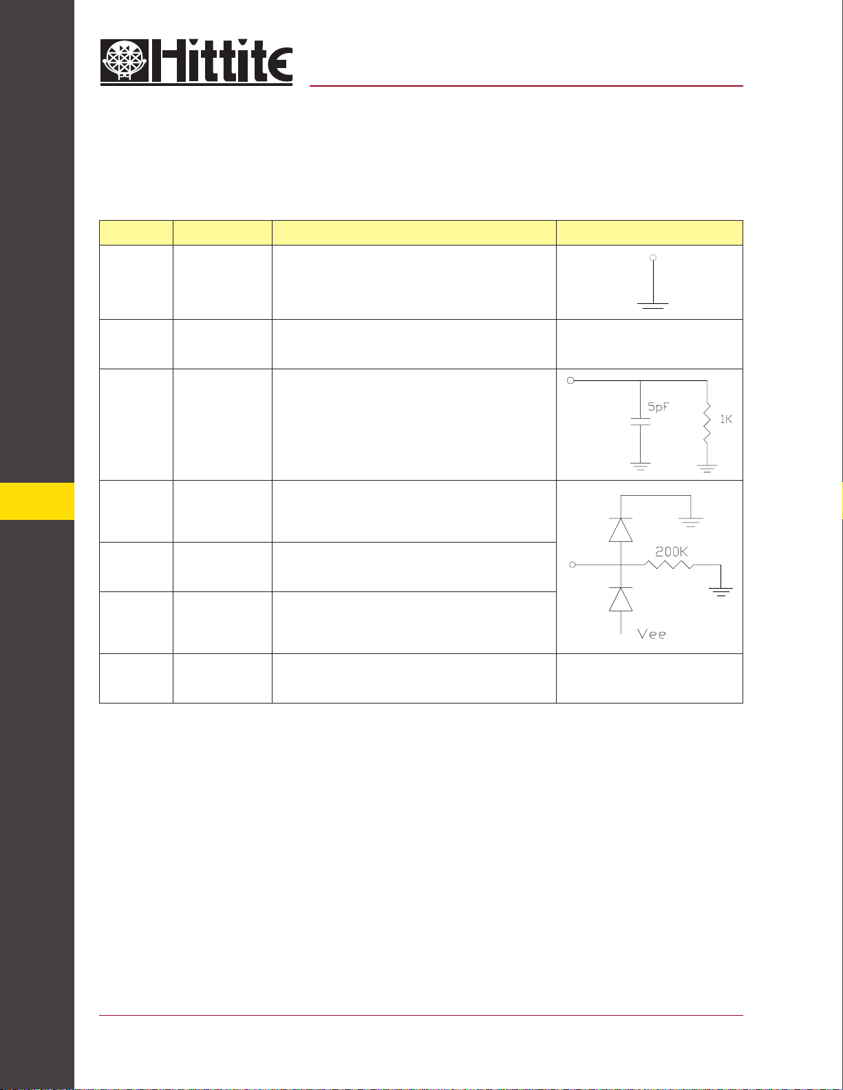
Pin Descriptions
Pin Number Function Description Interface Schematic
14
1, 3, 5, 7, 12,
14, 16, 18,
21, 23
2, 4, 6, 13, 15,
17, 19, 22, 24
8 VEE Supply Voltage =5V ± 10%
9 CTLC See truth table and control voltage table.
10 CTLB See truth table and control voltage table.
11 CTLA See truth table and control voltage table.
GND
RF1 - RF8
& RFC
Package bottom has exposed metal paddle that must also be
connected to PCB RF ground.
This pin is DC coupled and matched to 50 Ohm. Blocking
capacitors are required if RF line potential is not equal to 0V.
20 N/C
SWITCHES - SMT
14 - 180
This pin should be connected to PCB RF ground to maximize
isolation.
For price, delivery, and to place orders, please contact Hittite Microwave Corporation:
12 Elizabeth Drive, Chelmsford, MA 01824 Phone: 978-250-3343 Fax: 978-250-3373
Order Online at www.hittite.com
Page 6
MICROWAVE CORPORATION
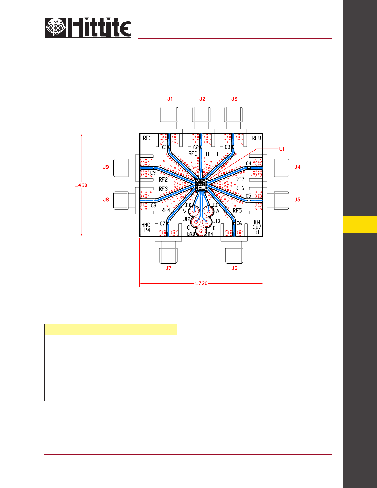
Evaluation PCB
v03.0604
HMC322LP4
GaAs MMIC SP8T NON-REFLECTIVE
SWITCH, DC - 8.0 GHz
List of Material
Item Description
J1 - J9 PC Mount SMA RF Connector
J10 - J14 DC Pin
C1 - C9 100 pF Capacitor, 0402 Pkg.
U1 HMC322LP4 SP8T Switch
PCB* 104687 Evaluation PCB 1.73”x1.46”
* Circuit Borad Material: Rogers 4350
The circuit board used in the fi nal application should
be generated with proper RF circuit design techniques.
Signal lines at the RF port should have 50 ohm impedance and the package ground leads and backside
ground slug should be connected directly to the ground
plane similar to that shown above. The evaluation circuit
board shown above is available from Hittite Microwave
Corporation upon request.
14
SWITCHES - SMT
For price, delivery, and to place orders, please contact Hittite Microwave Corporation:
12 Elizabeth Drive, Chelmsford, MA 01824 Phone: 978-250-3343 Fax: 978-250-3373
Order Online at www.hittite.com
14 - 181
 Loading...