

Page 1

查询HMC170C8供应商
12
MICROWAVE CORPORATION
Typical Applications
The HMC170C8 is ideal for:
• Microwave Point to Point
• RADAR
• VSAT
Functional Diagram
v01.0801
HMC170C8
GaAs MMIC SMT DOUBLE-
BALANCED MIXER, 2.5 - 4 GHz
Features
Conversion Loss: 9.0 dB
LO to RF Isolation: 45 dB
Surface Mount
Small Size, No DC Bias Required
General Description
The HMC170C8 is a miniature double-balanced
mixer in a non-hermetic ceramic surface mount
package that can be used as an upconverter,
downconverter or biphase modulator. The device
is a passive diode/balun type mixer with high
dynamic range. Noise fi gure is essentially equal
to the conversion loss. The mixer can handle
larger signal levels than most active mixers due
to the high third order intercept. MMIC implementation provides exceptional balance in the circuit
resulting in high LO/RF and LO/IF isolations and
unit-to-unit consistency. This mixer has applications where small size and surface mount compatibility are important.
MIXERS - SMT
Electrical Specifi cations, T
Frequency Range, RF & LO 2.5 - 4.0 GHz
Frequency Range, IF DC - 2 GHz
Conversion Loss 910 dB
Noise Figure (SSB) 910 dB
LO to RF Isolation 40 45 dB
LO to IF Isolation 32 36 dB
IP3 (Input) 13 18 dBm
IP2 (Input) 35 40 dBm
1 dB Gain Compression (Input) 7 10 dBm
12 - 22
= +25° C, LO Drive = +13 dBm
A
Parameter Min. Typ. Max. Units
For price, delivery, and to place orders, please contact Hittite Microwave Corporation:
12 Elizabeth Drive, Chelmsford, MA 01824 Phone: 978-250-3343 Fax: 978-250-3373
Order Online at www.hittite.com
Page 2
MICROWAVE CORPORATION
v01.0801
HMC170C8
GaAs MMIC SMT DOUBLE-
BALANCED MIXER, 2.5 - 4 GHz
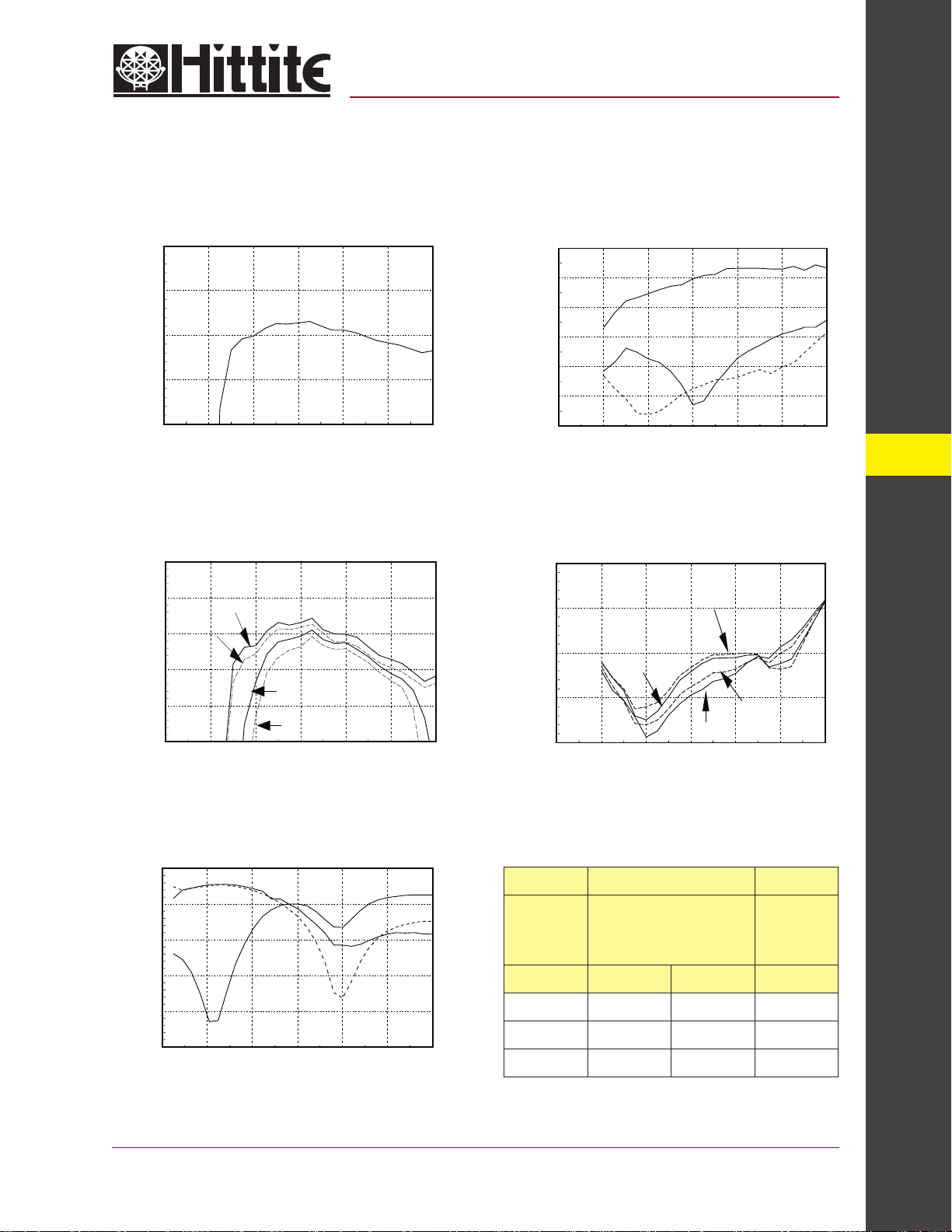
Conversion Loss
0
-5
-10
-15
CONVERSION LOSS (dB)
-20
0123456
FREQUENCY (GHz)
Conversion Loss vs. LO Drive
-5
-7
-9
-11
-13
CONVERSION LOSS (dB)
-15
01 23 4 56
+15 dBm
+13 dBm
+10 dBm
+9 dBm
FREQUENCY (GHz)
Isolation
0
-10
-20
-30
-40
ISOLATION (dB)
-50
-60
0123456
RF/IF
FREQUENCY (GHz)
Isolation vs. LO Drive
-20
-30
-40
ISOLATION (dB)
-50
-60
01 23456
+10 dBm
FREQUENCY (GHz)
+9 dBm
+15 dBm
LO/IF
LO/RF
12
+13 dBm
MIXERS - SMT
Return Loss
0
-5
-10
-15
-20
RETURN LOSS (dB)
-25
01 23456
For price, delivery, and to place orders, please contact Hittite Microwave Corporation:
12 Elizabeth Drive, Chelmsford, MA 01824 Phone: 978-250-3343 Fax: 978-250-3373
Distortion and 1dB
Compression vs. LO Drive Level
Distortion
LO
IF
RF
FREQUENCY (GHz)
LO
Drive
(dBm) IP3 (dBm) IP2 (dBm) P1dB (dBm)
+10 16 38 8
+13 18 40 10
+15 18 40 10
S - Paremeters for the RF, LO, IF Ports are Available On-Line at www.hittite.com
Order Online at www.hittite.com
RF (f1) = 3.01 GHz
RF (f2) = 3.00 GHz
LO = 3.5 GHz
RF Level = 0 dBm
1 dB
Compression
12 - 23
Page 3
12
MICROWAVE CORPORATION
v01.0801
Absolute Maximum Ratings
RF / IF Input +13 dBm
LO Drive +27 dBm
Storage Temperature -65 to +150 °C
Operating Temperature -55 to +85 °C
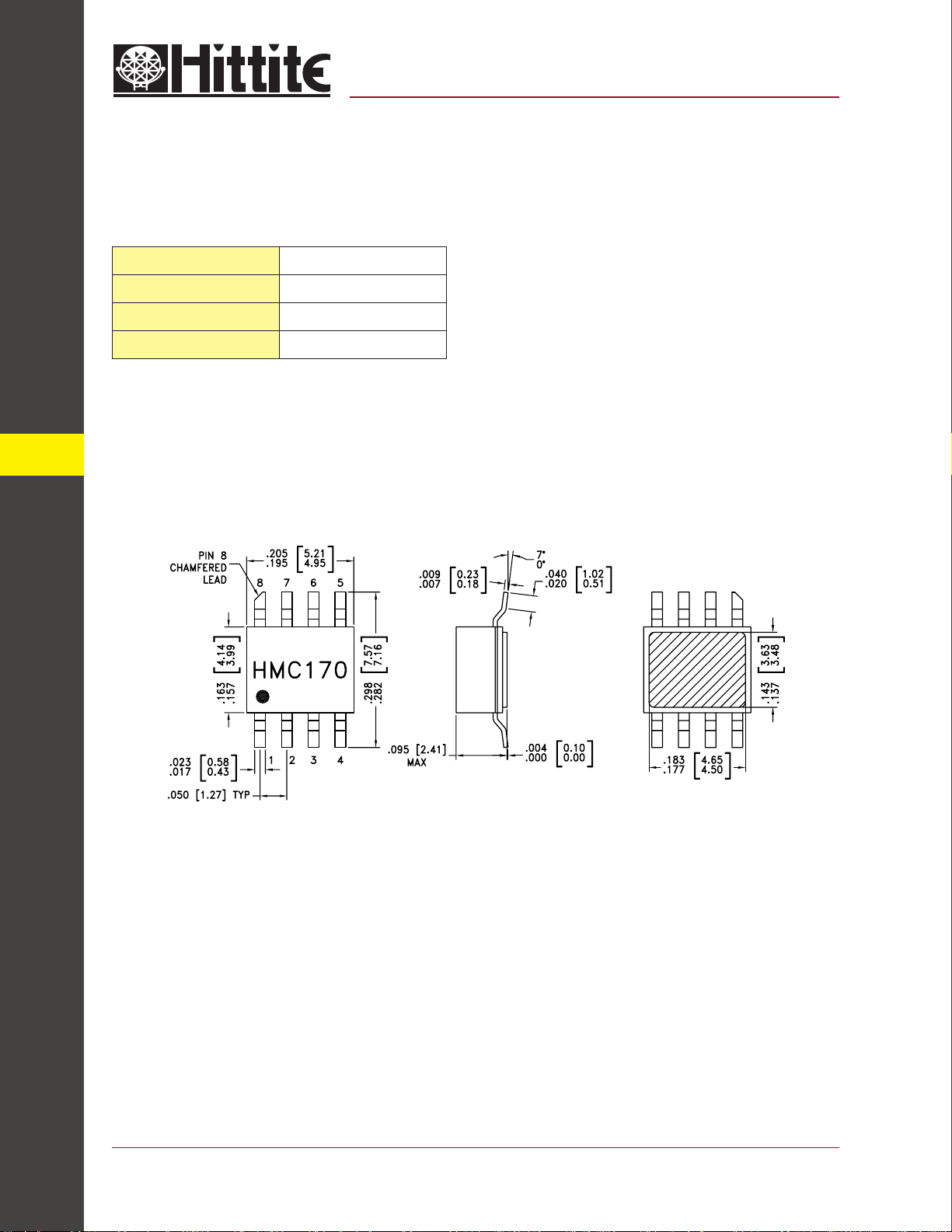
Outline Drawing
HMC170C8
GaAs MMIC SMT DOUBLE-
BALANCED MIXER, 2.5 - 4 GHz
MIXERS - SMT
12 - 24
NOTES:
1. PACKAGE BODY MATERIAL: WHITE ALUMINA 92%
2. LEAD, PACKAGE BOTTOM MATERIAL: COPPER
3. PLATING: ELECTROLYTIC GOLD 100-200 MICROINCHES, OVER
ELECTROLYTIC NICKEL 100-250 MICROINCHES.
4. DIMENSIONS ARE IN INCHES [MILLIMETERS].
5. PACKAGE LENGTH AND WIDTH DIMENSIONS DO NOT INCLUDE LID
SEAL PROTRUSION .005 PER SIDE.
6. ALL GROUND LEADS AND GROUND PADDLE MUST BE SOLDERED
TO PCB RF GROUND.
For price, delivery, and to place orders, please contact Hittite Microwave Corporation:
12 Elizabeth Drive, Chelmsford, MA 01824 Phone: 978-250-3343 Fax: 978-250-3373
Order Online at www.hittite.com
Page 4
MICROWAVE CORPORATION
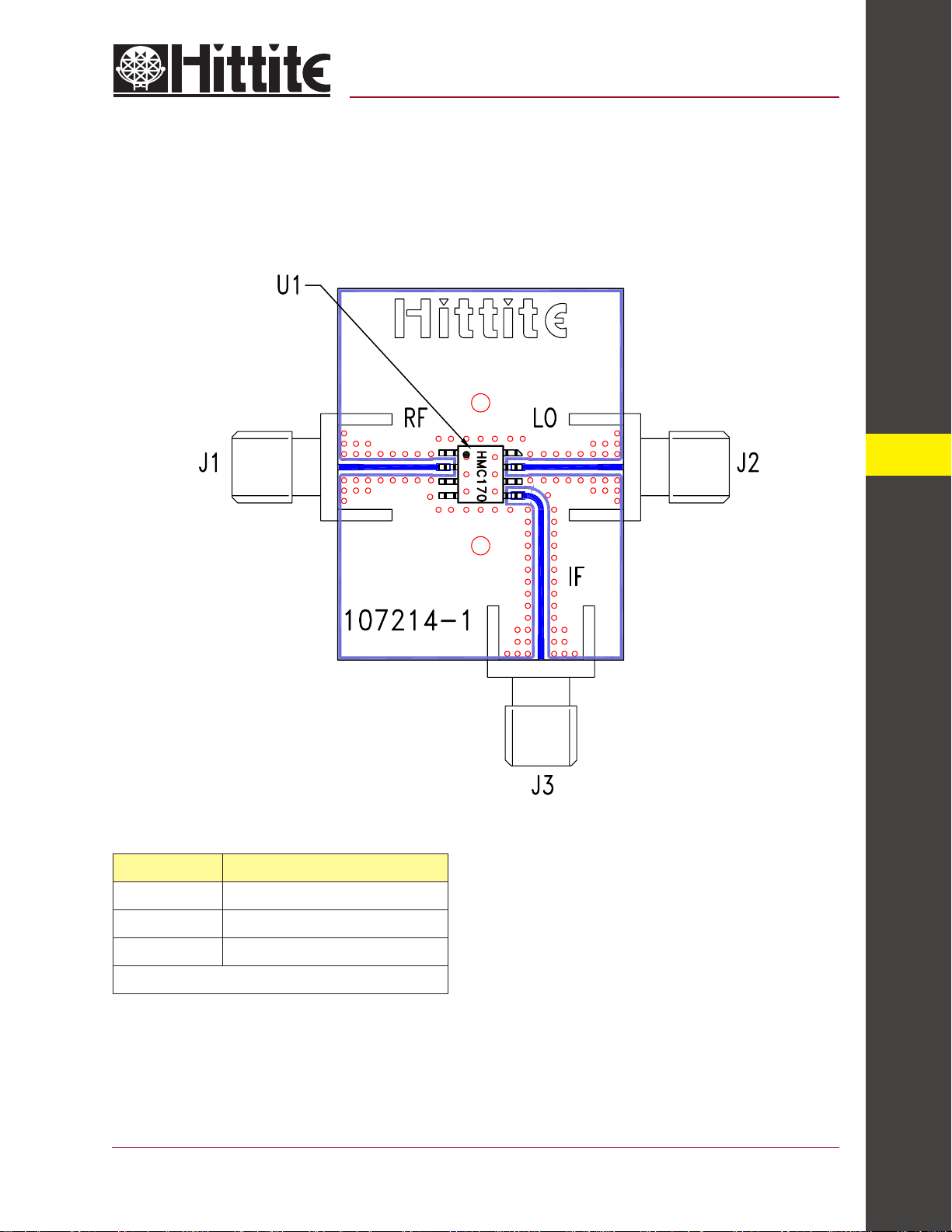
Evaluation PCB
v01.0801
HMC170C8
GaAs MMIC SMT DOUBLE-
BALANCED MIXER, 2.5 - 4 GHz
12
List of Material
Item Description
J1 - J3 PC Mount SMA RF Connector
U1 HMC170C8 Mixer
PCB* 107214 Evaluation Board
* Circuit Board Material: Rogers 4350
For price, delivery, and to place orders, please contact Hittite Microwave Corporation:
12 Elizabeth Drive, Chelmsford, MA 01824 Phone: 978-250-3343 Fax: 978-250-3373
The circuit board used in the fi nal application should
use RF circuit design techniques. Signal lines should
have 50 ohm impedance while the package ground
leads and exposed paddle should be connected
directly to the ground plane similar to that shown. A
suffi cient number of VIA holes should be used to connect the top and bottom ground planes. The evaluation circuit board shown is available from Hittite upon
request.
Order Online at www.hittite.com
MIXERS - SMT
12 - 25
 Loading...