

Page 1
查询HMC129供应商
5
MICROWAVE CORPORATION
Typical Applications
The HMC129 is ideal for:
• Microwave & VSAT Radios
• T est Equipment
• Military EW, ECM, C
• Space Telecom
3
I
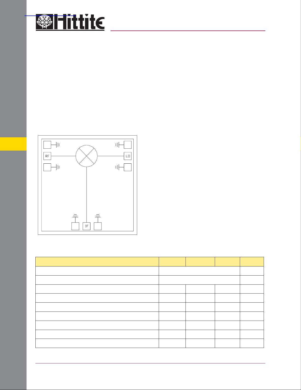
Functional Diagram
v02.0802
HMC129
GaAs MMIC DOUBLE-BALANCED
MIXER, 4 - 8 GHz
Features
Conversion Loss: 7 dB
LO to RF and IF Isolation: 40 dB
Input IP3: +17 dBm
Small Size, No DC Bias Required
General Description
The HMC129 chip is a miniature double-balanced mixer which can be used as an upconverter or downconverter in the 4 to 8 GHz band.
The chip can be integrated directly into hybrid
MICs without DC bias or external baluns to provide an extremely compact mixer. It is ideally
suited for applications where small size, no DC
bias, and consistent IC performance are required.
This mixer can operate ov er a wide LO drive input
of +9 to +15 dBm. It performs equally well as a
Bi-Phase modulator or demodulator. See the
HMC136 data sheet.
MIXERS - CHIP
Electrical Specifi cations,
Frequency Range, RF & LO 4.0 - 8.0 GHz
Frequency Range, IF DC - 3.0 GHz
Conversion Loss 79dB
Noise Figure (SSB) 79dB
LO to RF Isolation 30 40 dB
LO to IF Isolation 35 42 dB
IP3 (Input) 13 17 dBm
IP2 (Input) 40 55 dBm
1 dB Gain Compression (Input) 6 10 dBm
* Unless otherwise noted, all measurements performed as downconverter, IF = 100 MHz
5 - 8
TA = +25° C, LO Drive = +15 dBm
Parameter Min. Typ. Max. Units
For price, delivery, and to place orders, please contact Hittite Microwave Corporation:
12 Elizabeth Drive, Chelmsford, MA 01824 Phone: 978-250-3343 Fax: 978-250-3373
Order Online at www.hittite.com
Page 2
MICROWAVE CORPORATION
v02.0802
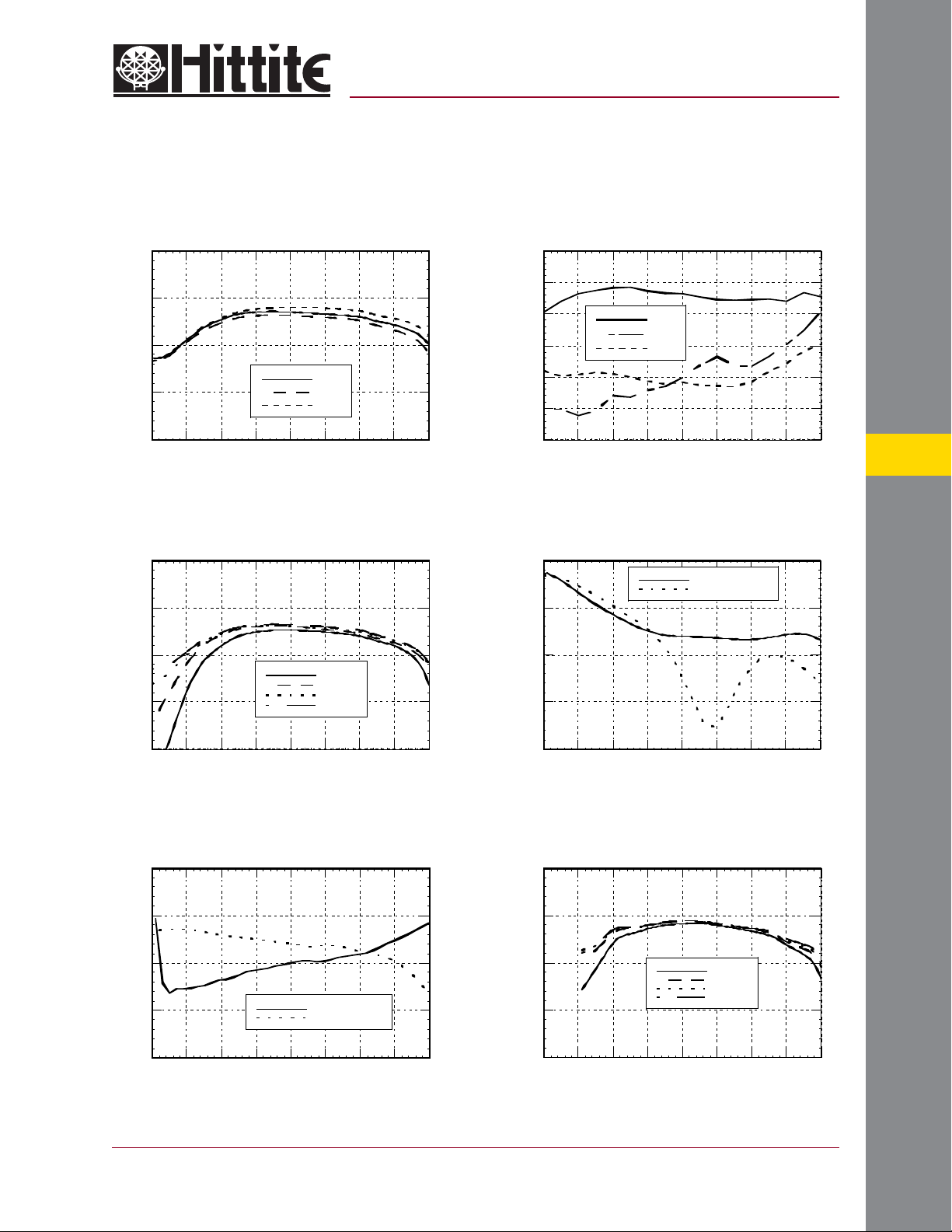
Conversion Gain vs. Temperature
LO = +15 dBm
HMC129
GaAs MMIC DOUBLE-BALANCED
MIXER, 4 - 8 GHz
Isolation @ LO = +15 dBm
0
-5
-10
+ 25 C
-15
CONVERSION GAIN (dB)
-20
2345678910
FREQUENCY (GHz)
+ 85 C
- 55 C
Conversion Gain vs. LO Drive
0
-5
-10
+ 9 dBm
+ 11 dBm
-15
CONVERSION GAIN (dB)
-20
2345678910
FREQUENCY (GHz)
+ 13 dBm
+ 15 dBm
0
-10
-20
-30
-40
ISOLATION (dB)
-50
-60
2345678910
RF/IF
LO/RF
LO/IF
FREQUENCY (GHz)
Return Loss @ LO = +15 dBm
0
LO RETURN LOSS
RF RETURN LOSS
-5
-10
RETURN LOSS (dB)
-15
-20
2345678910
FREQUENCY (GHz)
5
MIXERS - CHIP
IF Bandwidth @ LO = +15 dBm
0
-5
-10
RESPONSE (dB)
-15
-20
0 0.5 1 1.5 2 2.5 3 3.5 4
FREQUENCY (GHz)
For price, delivery, and to place orders, please contact Hittite Microwave Corporation:
12 Elizabeth Drive, Chelmsford, MA 01824 Phone: 978-250-3343 Fax: 978-250-3373
IF RETURN LOSS
IF BANDWIDTH
Unconverter Performance
Conversion Gain vs. LO Drive
0
-5
-10
-15
CONVERSION GAIN (dB)
-20
2345678910
Order Online at www.hittite.com
+ 9 dBm
+ 11 dBm
+ 13 dBm
+ 15 dBm
FREQUENCY (GHz)
5 - 9
Page 3
MICROWAVE CORPORATION
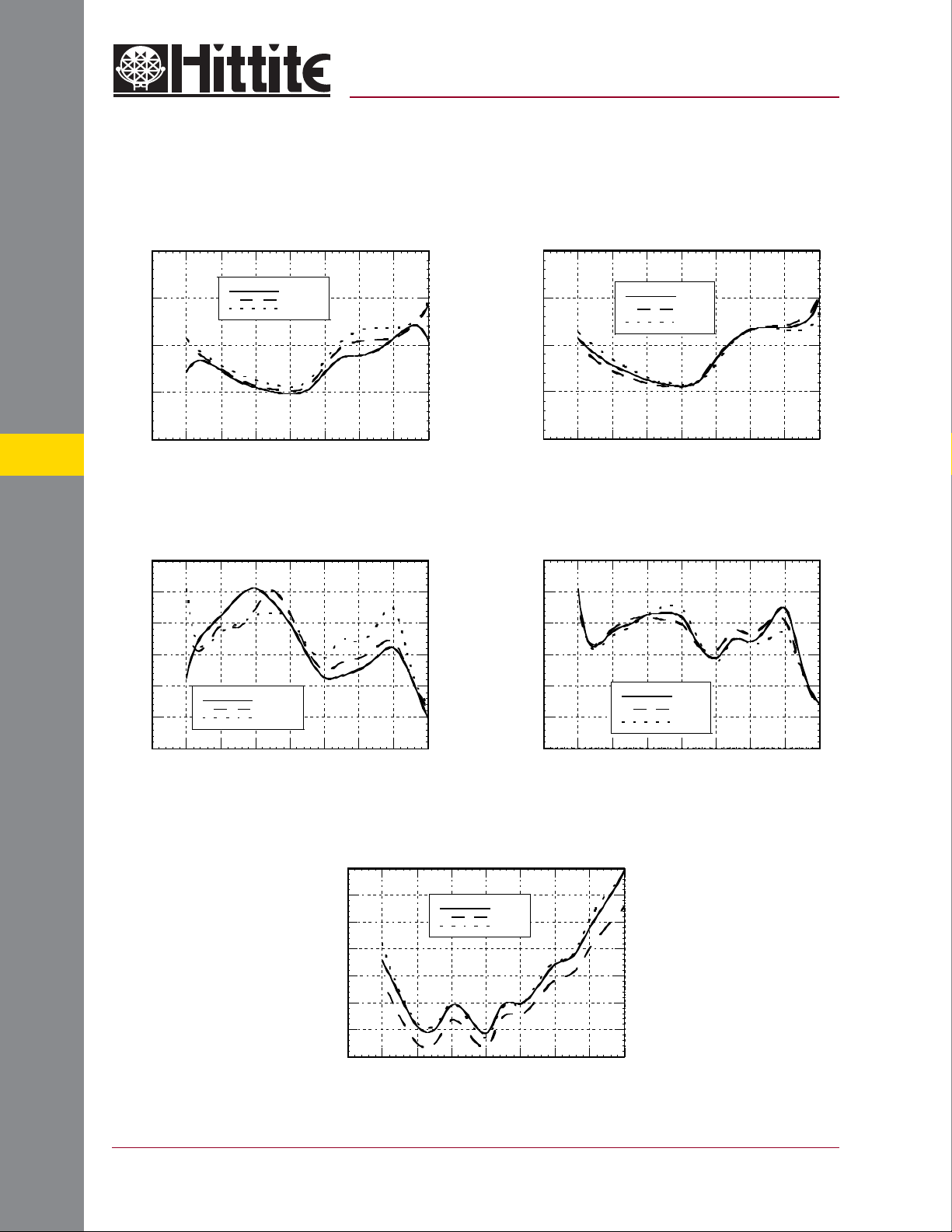
Input IP3 vs. LO Drive
v02.0802
HMC129
GaAs MMIC DOUBLE-BALANCED
MIXER, 4 - 8 GHz
Input IP3 vs. Temperature
@ LO = +15 dBm
30
25
20
INPUT IP3 (dBM)
15
10
5
2345678910
Input IP2 vs. LO Drive
80
70
60
50
40
INPUT IP2 (dBm)
MIXERS - CHIP
30
20
2345678910
+ 11 dBM
+ 13 dBm
+ 15 dBm
FREQUENCY (GHz)
+ 11 dBm
+ 13 dBm
+ 15 dBm
FREQUENCY (GHz)
30
25
20
INPUT IP3 (dBm)
15
10
2345678910
+ 25 C
+ 85 C
- 55 C
FREQUENCY (GHz)
Input IP2 vs. Temperature
@ LO = +15 dBm
80
70
60
50
INPUT IP2 (dBm)
40
30
20
2345678910
+ 25 C
+ 85 C
- 55 C
FREQUENCY (GHz)
5 - 10
Input P1dB vs. Temperature
@ LO = +15 dBm
15
14
13
12
11
10
INPUT P1dB (dBm)
9
8
2345678910
FREQUENCY (GHz)
For price, delivery, and to place orders, please contact Hittite Microwave Corporation:
12 Elizabeth Drive, Chelmsford, MA 01824 Phone: 978-250-3343 Fax: 978-250-3373
Order Online at www.hittite.com
+ 25 C
+ 85 C
- 55 C
Page 4
MICROWAVE CORPORATION
v02.0802
HMC129
GaAs MMIC DOUBLE-BALANCED
MIXER, 4 - 8 GHz
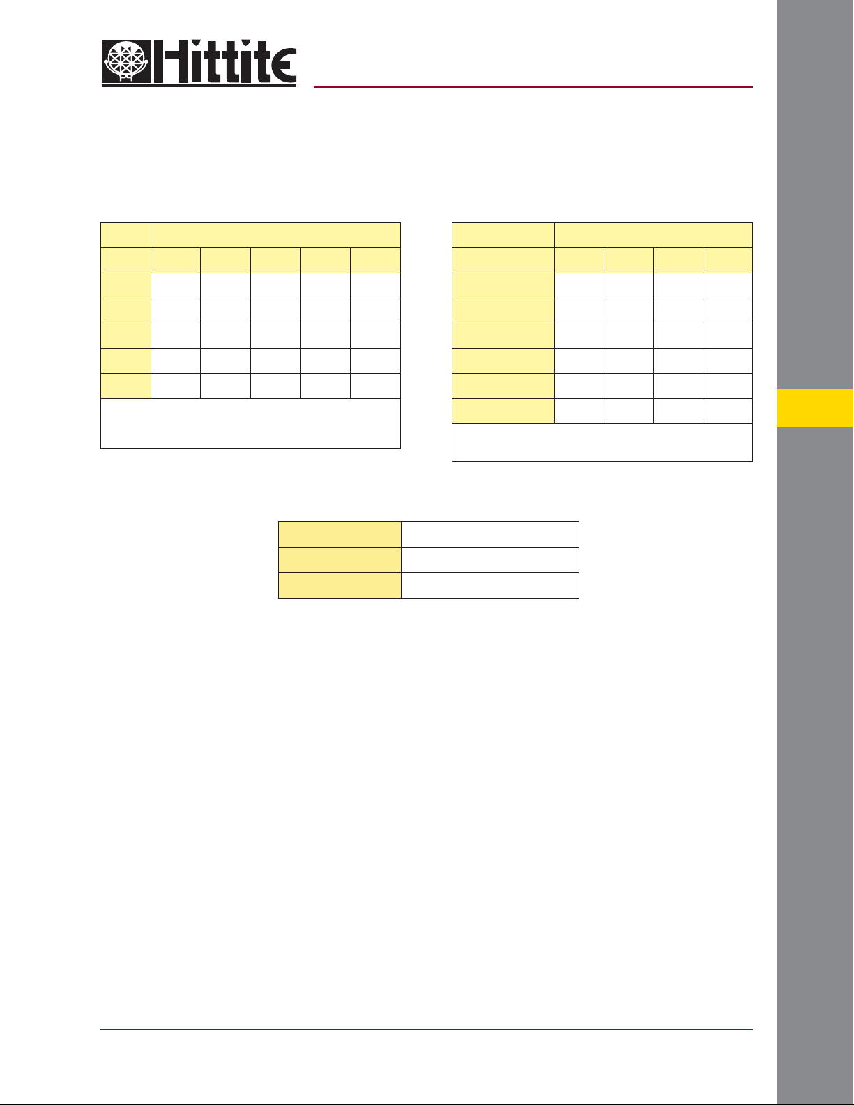
Harmonics of LOMxN Spurious @ IF Port
nLO
mRF01234
0 xx 13.66 26.83 9.16 38.33
1 8.16 0 31.33 49.33 43.5
2 78.5 80.16 75.16 79.16 76.66
3 76.0 80.0 81.16 64.5 78.66
4 73.83 77.83 80.0 81.83 82.0
RF Freq. = 6.1 GHz @ -10 dBm
LO Freq. = 6.0 GHz @ +13 dBm
Measured as downconverter
Absolute Maximum Ratings
LO Drive +27 dBm
Storage Temperature -65 to +150 °C
Operating Temperature -55 to +85 °C
nLO Spur @ RF Port
LO Freq. (GHz) 1 2 3 4
4 -30.7 -33.5 -32.7 -56.7
5 -29.2 -57.3 -64.8 -43.8
6 -24.7 -41.8 -35.0 -43.0
7 -19.7 -42.5 -20.5 -45.7
8 -23.3 -45.7 -22.5 -46.8
9 -17.2 -36.8 -26.7 -68.7
LO = +13 dBm
All values in dBc below input LO level measured at RF port
5
For price, delivery, and to place orders, please contact Hittite Microwave Corporation:
12 Elizabeth Drive, Chelmsford, MA 01824 Phone: 978-250-3343 Fax: 978-250-3373
Order Online at www.hittite.com
MIXERS - CHIP
5 - 11
Page 5
5
MICROWAVE CORPORATION
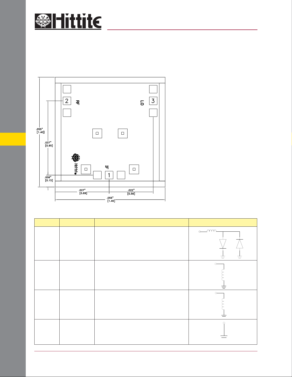
Outline Drawing
v02.0802
HMC129
GaAs MMIC DOUBLE-BALANCED
MIXER, 4 - 8 GHz
NOTES:
1. ALL DIMENSIONS ARE IN INCHES [MM]
2. BOND PADS ARE .004” SQUARE
3. TYPICAL BOND PAD SPACING CENTER TO CENTER
IS .006” EXCEPT AS SHOWN
4. DIE THICKNESS = .004” [.100 MM]
5. BACKSIDE METALIZATION: GOLD
6. BACKSIDE METAL IS GROUND
7. BOND PAD METALIZATION: GOLD
Pad Descriptions
MIXERS - CHIP
Pad Number Function Description Interface Schematic
1IF
2RF
3LO
GND The backside of the die must connect to RF ground.
This pin is DC coupled. For applications not requiring opera-
tion to DC, this port should be DC blocked externally using a
series capacitor whose value has been chosen to pass the
necessary IF frequency range. For operation to DC this pin
must not source or sink more than 2mA of current or die non-
function and possible die failure will result.
This pin is DC coupled and matched to 50 Ohm
from 4 to 8 GHz.
This pin is DC coupled and matched to 50 Ohm
from 4 to 8 GHz.
5 - 12
For price, delivery, and to place orders, please contact Hittite Microwave Corporation:
12 Elizabeth Drive, Chelmsford, MA 01824 Phone: 978-250-3343 Fax: 978-250-3373
Order Online at www.hittite.com
Page 6
MICROWAVE CORPORATION
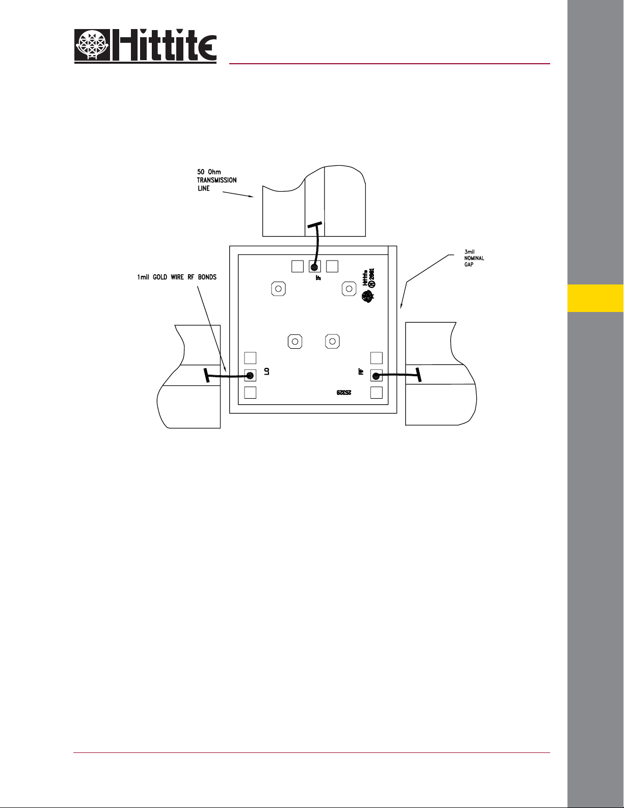
Assembly Diagram
v02.0802
HMC129
GaAs MMIC DOUBLE-BALANCED
MIXER, 4 - 8 GHz
5
Handling Precautions
Follow these precautions to avoid permanent damage.
Cleanliness: Handle the chips in a clean environment. DO NOT attempt to clean the chip using liquid cleaning systems.
Static Sensitivity: Follow ESD precautions to protect against > ± 250V ESD strikes.
Transients: Suppress instr ument and bias supply transients while bias is applied. Use shielded signal and bias cables to minimize
inductive pick-up.
General Handling: Handle the chip along the edges with a vacuum collet or with a sharp pair of bent tweezers. The surface of the
chip has fragile air bridges and should not be touched with vacuum collet, tweezers, or fi ngers.
Mounting
The chip is back-metallized and can be die mounted with AuSn eutectic preforms or with electrically conductive epoxy. The mounting
surface should be clean and fl at.
Eutectic Die Attach: A 80/20 gold tin preform is recommended with a work surface temperature of 255 °C and a tool temperature
of 265 °C. When hot 90/10 nitrogen/hydrogen gas is applied, tool tip temperature should be 290 °C. DO NOT expose the chip
to a temperature greater than 320 °C for more than 20 seconds. No more than 3 seconds of scr ubbing should be required for
attachment.
Epoxy Die Attach: Apply a minimum amount of epoxy to the mounting surface so that a thin epoxy fi llet is obser ved around the
perimeter of the chip once it is placed into position. Cure epoxy per the manufacturer’s schedule.
Wire Bonding
Ball or wedge bond with 0.025 mm (1 mil) diameter pure gold wire. Thermosonic wirebonding with a nominal stage temperature of
150 °C and a ball bonding force of 40 to 50 grams or wedge bonding force of 18 to 22 grams is recommended. Use the minimum
level of ultrasonic energy to achieve reliable wirebonds. Wirebonds should be started on the chip and terminated on the package or
substrate. All bonds should be as short as possible <0.31 mm (12 mils).
For price, delivery, and to place orders, please contact Hittite Microwave Corporation:
12 Elizabeth Drive, Chelmsford, MA 01824 Phone: 978-250-3343 Fax: 978-250-3373
Order Online at www.hittite.com
MIXERS - CHIP
5 - 13
 Loading...