

Page 1
T-13/4, 2 mm X 5 mm Rectangular
Bicolor LED Lamps
High Efficiency Red/
High Performance Green
H
Technical Data
Features:
• Two Color (Red, Green)
Operation
• (Other Two LED Color
Combinations Available)
• Three Leads with One
Common Cathode
• Option of Straight or Spread
Lead Configurations
• Diffused, Wide Visibility
Lens
Description
The T-1 3/4 HLMP-4000 and
2 mm by 5 mm rectangular
HLMP-0800 are three leaded
bicolor light sources designed for
a variety of applications where
dual state illumination is required
in the same package. There are
two LED chips, high efficiency
red (HER), and high performance
green (Green), mounted on a
central common cathode lead for
maximum on-axis viewability.
Colors between HER and Green
can be generated by
independently pulse width
modulating the LED chips.
HLMP-4000
HLMP-0800
Other Bicolor Combinations
Other bicolor combinations are
available:
• HER/yellow
• HER/green
• DH AlGaAs red/green.
Contact your local HewlettPackard Components Field Sales
representative for details.
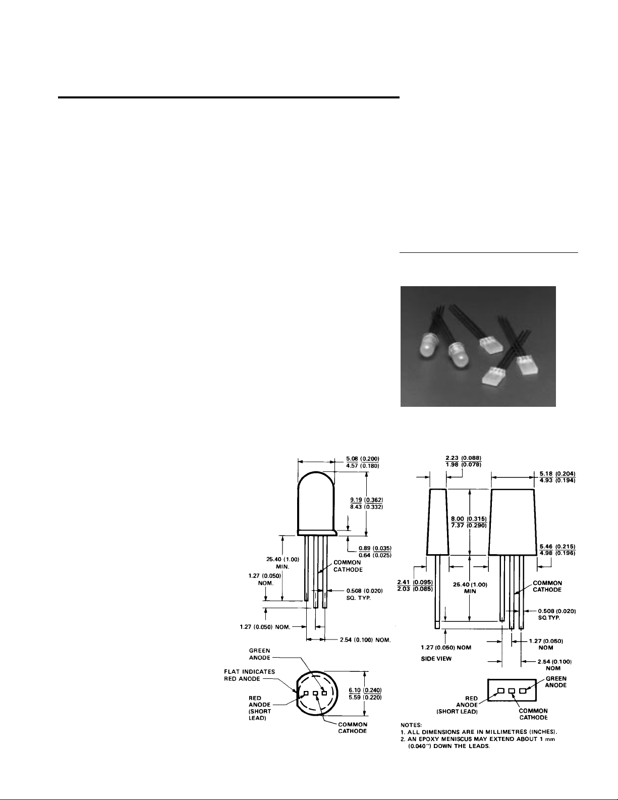
Package Dimensions
HLMP-4000 HLMP-0800
5964-9363E
1-157
Page 2
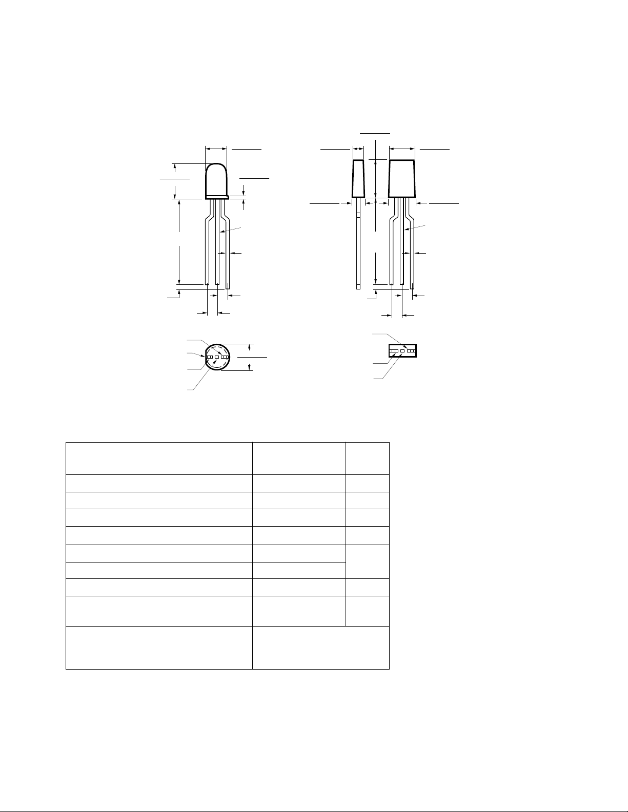
Package Dimensions, continued
5.08 (0.200)
4.57 (0.180)
2.23 (0.088)
1.98 (0.078)
8.00 (0.315)
7.37 (0.290)
5.18 (0.204)
4.93 (0.194)
9.19 (0.362)
8.43 (0.332)
20.32
(0.800)
2.54 ± 0.25
(0.100 ± 0.010)
COMMON CATHODE
2.54 ± 0.25
(0.100 ± 0.010)
GREEN
ANODE
FLAT INDICATES
RED ANODE
RED ANODE
(SHORT LEAD)
MIN.
0.89 (0.035)
0.64 (0.025)
COMMON
CATHODE
0.508
(0.020)
2.54 ± 0.25
(0.100 ± 0.010)
6.10 (0.240)
5.59 (0.220)
Absolute Maximum Ratings at T
Parameter Red/Green Units
2.41 (0.095)
2.03 (0.085)
SQUARE
NOMINAL
COMMON CATHODE
NOTES:
1. ALL DIMENSIONS ARE IN MILLIMETERS (INCHES).
2. AN EPOXY MENISCUS MAY EXTEND ABOUT
1 MM (0.040") DOWN THE LEADS.
= 25°C
A
High Efficiency
SIDE VIEW
2.54 ± 0.25
(0.100 ± 0.010)
2.54 ± 0.25
(0.100 ± 0.010)
GREEN
ANODE
RED ANODE
(SHORT LEAD)
20.32
(0.800)
MIN.
5.46 (0.215)
4.98 (0.196)
COMMON
CATHODE
SQUARE
0.508
NOMINAL
(0.020)
2.54 ± 0.25
(0.100 ± 0.010)
Peak Forward Current 90 mA
Average Forward Current
DC Current
Power Dissipation
[2,4]
(Total) 30 mA
[3,5]
Operating Temperature Range -20 to +85
[1,2]
(Total) 25 mA
(Total) 135 mW
°C
Storage Temperature Range -55 to +100
Reverse Voltage (IR = 100 µA) 5 V
Transient Forward Current
[6]
500 mA
(10 µsec Pulse)
Lead Soldering Temperature
[1.6 mm (0.063 in.) below 260°C for 5 seconds
seating plane]
Notes:
1. See Figure 5 to establish pulsed operating conditions.
2. The combined simultaneous current must not exceed the maximum.
3. The combined simultaneous power must not exceed the maximum.
4. For HER and Green derate linearly from 50°C at 0.5 mA/°C.
5. For HER and Green derate linearly from 25°C at 1.8 mW/°C.
6. The transient peak current is the maximum non-recurring current that can be applied
to the device without damaging the LED die and wirebond. It is not recommended that
the device be operated at peak currents beyond the peak forward current listed in the
Absolute Maximum Ratings.
1-158
Page 3

Electrical/Optical Characteristics at T
= 25°C
A
Red Green
Test
Sym. Parameter Min. Typ. Max. Min. Typ. Max. Units Conditions
I
V
Luminous Intensity
HLMP-4000 2.1 5 4.2 8 IF = 10 mA
mcd
HLMP-0800 2.1 3.5 2.6 4.0 IF = 20 mA
λ
λ
τ
s
PEAK
d
Peak Wavelength 635 565 nm
Dominant 626 569
Wavelength
[1]
Speed of Response 90 500 ns
C Capacitance 11 18 pF VF = 0, f = 1 MHz
V
F
V
R
Forward Voltage 1.9 2.4 2.1 2.7 V IF = 10 mA
Reverse Breakdown 5 5 V IR = 100 µA
Voltage
Rθ
Thermal Resistance 260 260 °C/W Junction to
J-PIN
Cathode Lead
Included Angle
Between Half
Luminous
[2]
Deg.
2θ 1/2
Intensity Points
HLMP-4000 65 65 IF = 10 mA
HLMP-0800 100 100 IF = 20 mA
η
V
Luminous Efficacy
[3]
145 595 Lumen/
Watt
Notes:
1. The dominant wavelength, λd, is derived from the CIE chromaticity diagram and represents the single wavelength which defines the
color of the device.
2. θ1/2 is the off-axis angle at which the luminous intensity is half the axial luminous intensity.
3. Radiant intensity, Ie, in watts steradian, may be found from the equation Ie = Iv/ηv where Iv is the luminous intensity in candelas and
ηv is the luminous efficacy in lumens/watt.
Figure 1. Relative Intensity vs. Wavelength.
1-159
Page 4

Figure 2. Forward Current vs.
Forward Voltage Characteristics.
Figure 3. Relative Luminous Intensity
vs. DC Forward Current.
Figure 4. Relative Efficiency
(Luminous Intensity per Unit
Current) vs. Peak LED Current.
Figure 5. Maximum Tolerable Peak Current vs.
Pulse Duration. (IDC MAX as per MAX
Ratings).
Figure 7. Relative Luminous Intensity vs. Angular
Displacement for the HLMP-0800.
1-160
Figure 6. Relative Luminous Intensity vs. Angular
Displacement for the HLMP-4000.
 Loading...