

Page 1
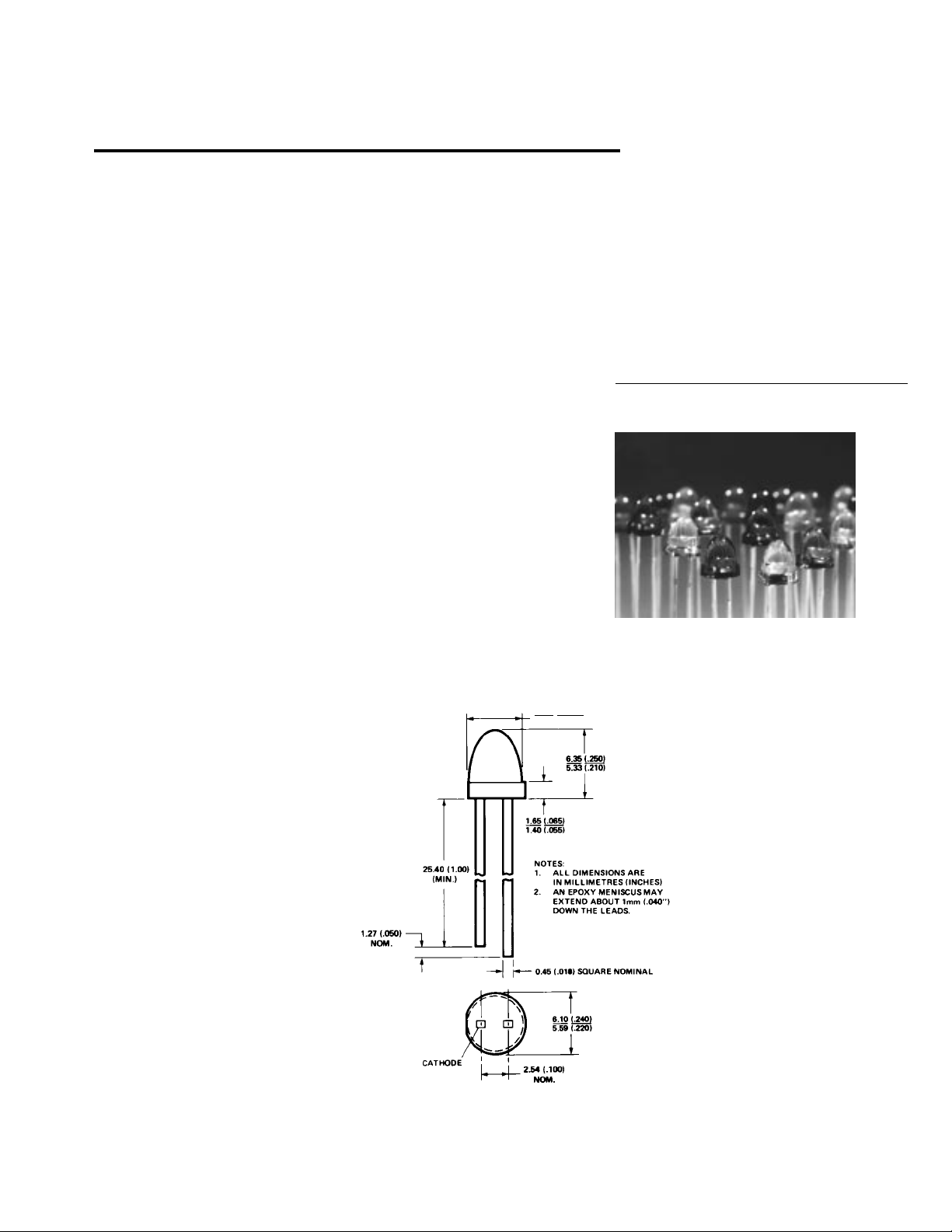
T-13/4 (5 mm) Low Profile
LED Lamps
Technical Data
H
HLMP-335X Series
HLMP-336X Series
HLMP-345X Series
HLMP-346X Series
HLMP-355X Series
HLMP-356X Series
Features
• High Intensity
• Low Profile: 5.8 mm
(0.23 in.) Nominal
• T-13/4 Diameter Package
• Diffused and Non-diffused
Types
• General Purpose Leads
• IC Compatible/Low Current
Requirements
• Reliable and Rugged
Description
The HLMP-335X/-336X Series are
Gallium Arsenide Phosphide on
Gallium Phosphide High
Efficiency Red Light Emitting
Diodes.
The HLMP-345X/-346X Series are
Gallium Arsenide Phosphide on
Gallium Phosphide Yellow Light
Emitting Diodes.
The HLMP-355X/-356X Series are
Gallium Phosphide Green Light
Emitting Diodes.
The Low Profile T-13/4 package
provides space savings and is
excellent for backlighting
applications.
Package Dimensions
5.34 (0.210)
4.83 (0.190)
5964-9295E
1-101
Page 2

Selection Guide
Part Minimum
Number Intensity @
HLMP- Application 10 mA (mcd) Lens
3350 Indicator – General Purpose 2.1 Tinted Diffused Wide Angle
3351 Indicator – High Brightness 5.4 HER
3365 General Purpose Point Source 8.6 Tinted Non-diffused Narrow Angle
3366 Indicator – High Brightness 13.8 HER
3450 Indicator – General Purpose 2.2 Tinted Diffused Wide Angle
3451 Indicator – High Brightness 5.7 Yellow
3465 General Purpose Point Source 5.7 Tinted Non-diffused Narrow Angle
3466 Indicator – High Brightness 9.2 Yellow
3553 Indicator – General Purpose 1.6 Tinted Diffused Wide Angle
3554 Indicator – High Brightness 6.7 Green
3567 General Purpose Point Source 4.2 Tinted Non-diffused Narrow Angle
3568 Indicator – High Brightness 10.6 Green
1-102
Page 3
High Efficiency Red HLMP-335X/-336X Series
Electrical Specifications at T
Symbol Description HLMP- Min. Typ. Max. Units Conditions
I
V
2θ1/2 Including Angle Between Half 3350 50 Deg. Note 1 (Figure 11)
λ
PEAK
λ
∆λ
τ
C Capacitance 11 pF VF = 0; f = 1 MHz
Rθ
J-PIN
V
V
η
Notes:
1. θ1/2 is the off-axis angle at which the luminous intensity is half the axial luminous intensity.
2. Dominant wavelength, λd, is derived from the CIE chromaticity diagram and represents the single wavelength which defines the color
of the device.
3. Radiant Intensity, Ie, in watts/steradian may be found from the equation Ie = Iv/ηv, where Iv is the luminous intensity in candelas and
ηv is the luminous efficacy in lumens/watt.
Axial Luminous Intensity 3350 2.1 3.5 mcd IF = 10 mA
Luminous Intensity Points 3351 50
Peak Wavelength 635 nm Measurement at
Dominant Wavelength 626 nm Note 2
d
Spectral Line Halfwidth 40 nm
1/2
Speed of Response 90 ns
s
Thermal Resistance 260 °C/W Junction to
Forward Voltage 1.9 2.4 V IF = 10 mA
F
Reverse Breakdown Voltage 5.0 V IR = 100 µA
R
Luminous Efficacy 145 lm/W Note 3
V
= 25°C
A
Device Test
3351 5.4 7.0 (Figure 8)
3365 8.6 10.0
3366 13.8 18.0
3365 45
3366 45
Peak (Figure 1)
Cathode Lead
(Figure 7)
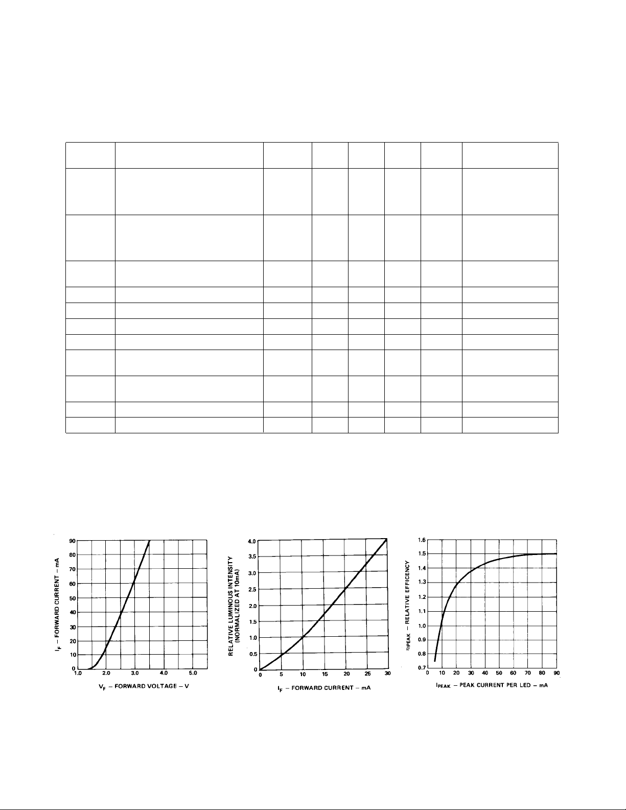
Figure 7. Forward Current vs.
Forward Voltage.
Figure 8. Relative Luminous Intensity
vs. Forward Current.
Figure 9. Relative Efficiency
(Luminous Intensity per Unit Current)
vs. Peak Current.
1-103
Page 4

Figure 10. Maximum Tolerable Peak
Current vs. Pulse Duration. (IDC MAX
as per MAX Ratings).
Figure 11. Relative Luminous Intensity vs. Angular
Displacement.
Yellow HLMP-345X/-346X Series
Electrical Specifications at T
Symbol Description HLMP- Min. Typ. Max. Units Conditions
I
V
2θ
1/2
λ
PEAK
λ
∆λ
τ
C Capacitance 15 pF VF = 0; f = 1 MHz
Rθ
J-PIN
V
V
R
η
Notes:
1. θ1/2 is the off-axis angle at which the luminous intensity is half the axial luminous intensity.
2. Dominant wavelength, λd, is derived from the CIE chromaticity diagram and represents the single wavelength which defines the color
of the device.
3. Radiant Intensity, Ie, in watts/steradian may be found from the equation Ie = Iv/ηv, where Iv is the luminous intensity in candelas and
ηv is the luminous efficacy in lumens/watt.
Axial Luminous Intensity 3450 2.2 4.0 mcd IF = 10 mA
Including Angle Between Half 3450 50 Deg. Note 1 (Figure 16)
Luminous Intensity Points 3451 50
Peak Wavelength 583 nm Measurement at
Dominant Wavelength 585 nm Note 2
d
Spectral Line Halfwidth 36 nm
1/2
Speed of Response 90 ns
s
Thermal Resistance 260 °C/W Junction to
Forward Voltage 2.0 2.4 V IF = 10 mA
F
Reverse Breakdown Voltage 5.0 V IR = 100 µA
Luminous Efficacy 500 lm/W Note 3
V
= 25°C
A
Device Test
3451 5.7 10.0 (Figure 13)
3465 5.7 12.0
3466 9.2 18.0
3465 45
3466 45
Peak (Figure 1)
Cathode Lead
(Figure 12)
1-104
Page 5

60
50
40
30
20
F
10
I – FORWARD CURRENT – mA
0
1.0 1.5 2.0 2.5 3.0 3.5 4.0
V – FORWARD VOLTAGE – V
F
Figure 12. Forward Current vs.
Forward Voltage.
Figure 15. Maximum Tolerable Peak
Current vs. Pulse Duration. (IDC MAX
as per MAX Ratings).
Figure 13. Relative Luminous
Intensity vs. Forward Current.
Figure 16. Relative Luminous Intensity vs. Angular Displacement.
Figure 14. Relative Efficiency
(Luminous Intensity per Unit Current)
vs. Peak Current.
1-105
Page 6

Green HLMP-355X/-356X Series
Electrical Specifications at T
Symbol Description HLMP- Min. Typ. Max. Units Conditions
I
V
2θ
λ
PEAK
λ
∆λ
τ
C Capacitance 18 pF VF = 0; f = 1 MHz
Rθ
J-PIN
V
V
η
Notes:
1. θ
is the off-axis angle at which the luminous intensity is half the axial luminous intensity.
1/2
2. Dominant wavelength, λd, is derived from the CIE chromaticity diagram and represents the single wavelength which defines the color
of the device.
3. Radiant Intensity, Ie, in watts/steradian may be found from the equation Ie = Iv/ηv, where Iv is the luminous intensity in candelas and
ηv is the luminous efficacy in lumens/watt.
Axial Luminous Intensity 3553 1.6 3.2 mcd IF = 10 mA
Including Angle Between Half 3553 50 Deg. Note 1 (Figure 21)
1/2
Luminous Intensity Points 3554 50
Peak Wavelength 565 nm Measurement at
Dominant Wavelength 569 nm Note 2
d
Spectral Line Halfwidth 28 nm
1/2
Speed of Response 500 ns
s
Thermal Resistance 260 °C/W Junction to
Forward Voltage 2.1 2.7 V IF = 10 mA
F
Reverse Breakdown Voltage 5.0 V IR = 100 µA
R
Luminous Efficacy 595 lm/W Note 3
V
= 25°C
A
Device Test
3554 6.7 10.0 (Figure 18)
3567 4.2 7.0
3568 10.6 15.0
3567 40
3568 40
Peak (Figure 1)
Cathode Lead
(Figure 17)
Figure 17. Forward Current vs.
Forward Voltage.
1-106
Figure 18. Relative Luminous
Intensity vs. Forward Current.
Figure 19. Relative Efficiency
(Luminous Intensity per Unit
Current) vs. Peak Current.
Page 7

Figure 20. Maximum Tolerable Peak
Current vs. Pulse Duration. (IDC MAX
as per MAX Ratings).
Figure 21. Relative Luminous Intensity vs. Angular Displacement.
1-107
 Loading...