

Page 1
0.075 (1.9)
0.063 (1.6)
0.010 (0.26)
0.002 (0.06)
0.056 (1.44)
0.048 (1.24)
0.024 (0.6)
0.016 (0.4)
0.091 (2.3)
0.083 (2.1)
0.020 (0.5)
0.012 (0.3)
0.276 (7.0)
MIN
0.058 (1.40)
0.050 (1.28)
EMITTER
0.087 (2.2)
0.079 (2.0)
0.031 (0.78)
0.023 (0.58)
ANODE
CATHODE MARK
(COLOR STRIPE ON SIDE OF PACKAGE)
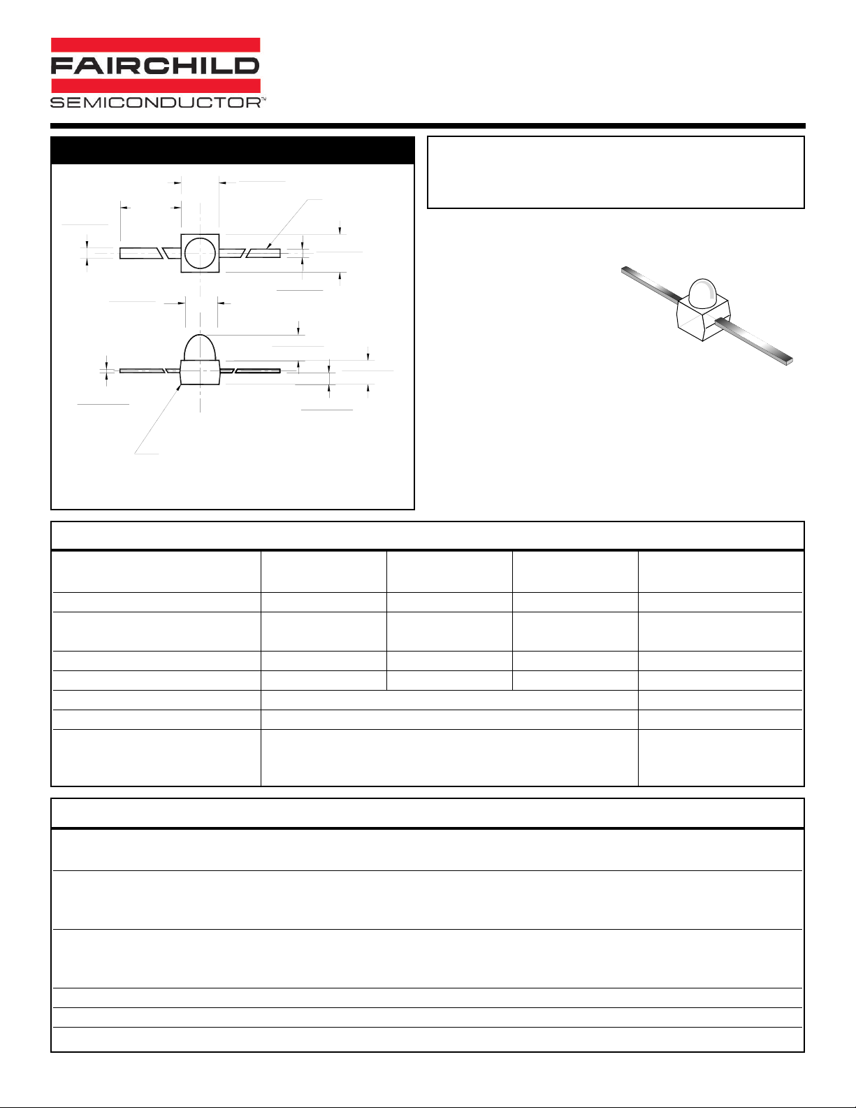
SOLID STATE LED LAMPS
SUBMINIATURE T-1 3/4 (1.9mm)
1 of 4 4/4/00 300049A
PACKAGE DIMENSIONS
FEATURES
• Subminiature package
• Low profile package
• Three lead bend options for
surface mounting
• Available in tape and reel
NOTE:
Dimensions are in inches (mm).
AlGaAs RED HLMP-Q106A Clear
AllnGaP ORANGE HLMA-QH00A Clear
AllnGaP YELLOW HLMA-QL00A Clear
DESCRIPTION
These subminiature LED lamps are intended for high volume,
low cost status indication on PCBs, as well as for backlighting
keyboards and switches. Choices of “Yoke”, “Z-Bend” or “GullWing” lead bends are available.
Parameter
AlGaAs Red AllnGaP Orange AllnGaP Yellow
Units
HLMP-Q106A HLMA-QH00A HLMA-QL00A
Continuous Forward Current - I
F
50 50 50 mA
Peak Forward Current - I
F
200 100 100 mA
(f = 1.0 KHz, Duty Factor = 1/10)
Reverse Voltage - VR (IR = 10 µA) 5 5 5 V
Power Dissipation - P
D
100 120 120 mW
Operating Temperature - T
OPR
-40 to +100 °C
Storage Temperature - T
STG
-40 to +100 °C
Lead Soldering Time - T
SOL
Wave 260 for 5 sec °C
Reflow 260 for 10 sec
ABSOLUTE MAXIMUM RATINGS
(TA= 25°C unless otherwise specified)
Part Number
AlGaAs Red AllnGaP Orange AllnGaP Yellow
Condition
HLMP-Q106A HLMA-QH00A HLMA-QL00A
Luminous Intensity (mcd) IF= 20mA
Minimum 50 150 150
Typical 500 500 500
Forward Voltage (V) IF= 20mA
Maximum 2.4 2.4 2.4
Typical 1.9 1.9 1.9
Peak Wavelength (nm) 660 620 590 IF= 20mA
Spectral Line Half Width (nm) 20 18 15 IF= 20mA
Viewing Angle (°) 25 25 25 IF= 20mA
ELECTRICAL / OPTICAL CHARACTERISTICS
(TA =25°C)
Page 2
2 of 4 4/4/00 300049A
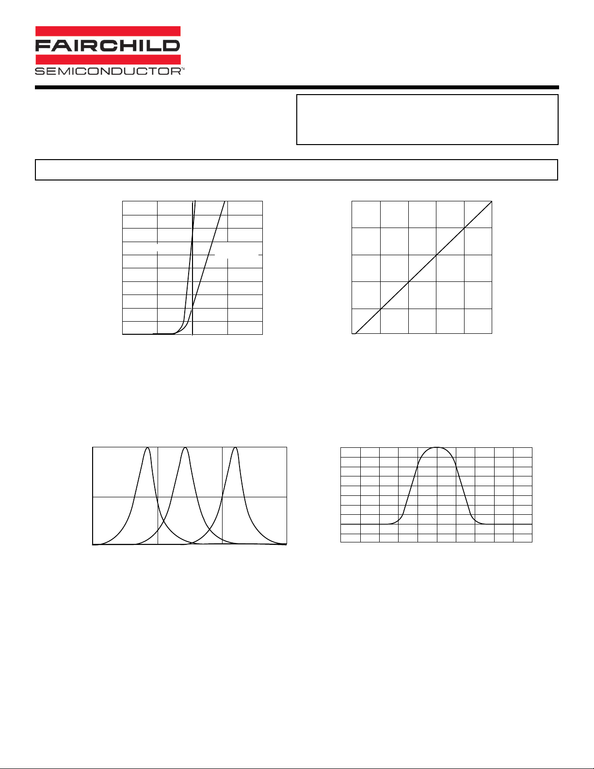
TYPICAL PERFORMANCE CURVES
SOLID STATE LED LAMPS
SUBMINIATURE T-1 3/4 (1.9mm)
AlGaAs RED HLMP-Q106A Clear
AllnGaP ORANGE HLMA-QH00A Clear
AllnGaP YELLOW HLMA-QL00A Clear
100
90
80
70
60
50
40
30
20
- FORWARD CURRENT (mA)
F
I
10
0
1.0 1.5 2.0 2.5 3.0
AlGaAs Red
VF - FORWARD VOLTAGE (V)
AllnGaP Y ellow
AllnGaP Orange
Fig. 1 Forward Current vs. Forward Voltage
1.0
AllnGaP Y ellow
0.5
RELATIVE INTENSITY
0
550 600 650 700 -50
AllnGaP Orange
AlGaAs Red
WAVELENGTH (nm) ANGULAR DISPLACEMENT - DEGREES
2.5
2.0
1.5
1.0
(NORMALIZED AT 20 mA)
0.5
RELATIVE LUMNOUS INTENSITY
0.0
02020304050
IF - DC FORWARD CURRENT (mA)
Fig. 2 Relative Luminous Intensity
vs. DC Forward Current
1.0
0.9
0.8
0.7
0.6
0.5
0.4
0.3
0.2
0.1
NORMALIZED INTENSITY
0
-40 -30 -20 -10 0 10 20 30 40 50
Fig. 3 Relative Intensity vs. Peak Wavelength Fig. 4 Relative Luminous Intensity
vs. Angular Displacement
Page 3

3 of 4 4/4/00 300049A
SOLID STATE LED LAMPS
SUBMINIATURE T-1 3/4 (1.9mm)
AlGaAs RED HLMP-Q106A Clear
AllnGaP ORANGE HLMA-QH00A Clear
AllnGaP YELLOW HLMA-QL00A Clear
NOTE
All dimensions are in inches (millimeters)
Call QT Optoelectronics for more information or the phone number of your nearest distributor.
United States 800-533-6786 • France 33 [0] 1.45.18.78.78 • Germany 49 [0] 89/96.30.51 • United Kingdom 44 [0] 1296 394499 • Asia/Pacific 603-7352417
www.qtopto.com
Yoke Lead Option
0.087 (2.21)
0.079 (2.01)
0.058 (1.48)
0.050 (1.28)
0.109 (2.76)
0.040 (1.02)
0.009 (0.23)
0.027 (0.68)
0.304 (7.72)
0.296 (7.52)
0.020 (0.50)
0.016 (0.4)
0.079 (2.00)
0.075 (1.90)
0.067 (1.70)
.026 [0.66]
0.045 (1.14)
Gull-Wing Lead Option
0.075 (1.91)
0.063 (1.60)
0.024 (0.61)
0.016 (0.41)
0.091 (2.31)
0.083 (2.11)
0.020 (0.51)
0.012 (0.30)
0.087 (2.21)
0.079 (2.01)
0.159 (4.05)
0.148 (3.75)
0.007 (0.1)
0.001 (.03)
0.016 (0.40)
0.008 (0.20)
0.058 (1.48)
0.050 (1.28)
0.035 (0.90)
0.028 (0.70)
Z-Bend Lead Option
0.087 (2.21)
0.079 (2.01)
0.058 (1.48)
0.050 (1.28)
0.027 (0.68)
0.075 (1.90)
0.067 (1.70)
.026 [0.66]
0.024 (0.61)
0.016 (0.41)
0.020 (0.51)
0.012 (0.30)
0.091 (2.31)
0.083 (2.11)
0.244 (6.20)
0.236 (6.00)
0.181 (4.60)
0.120 (3.04)
Page 4

4 of 4
SOLID STATE LED LAMPS
SUBMINIATURE T-1 3/4 (1.9mm)
4/4/00 300049A
DISCLAIMER
FAIRCHILD SEMICONDUCTOR RESERVES THE RIGHT TO MAKE CHANGES WITHOUT FURTHER NOTICE TO
ANY PRODUCTS HEREIN TO IMPROVE RELIABILITY, FUNCTION OR DESIGN. FAIRCHILD DOES NOT ASSUME
ANY LIABILITY ARISING OUT OF THE APPLICATION OR USE OF ANY PRODUCT OR CIRCUIT DESCRIBED HEREIN;
NEITHER DOES IT CONVEY ANY LICENSE UNDER ITS PATENT RIGHTS, NOR THE RIGHTS OF OTHERS.
LIFE SUPPORT POLICY
FAIRCHILD’S PRODUCTS ARE NOT AUTHORIZED FOR USE AS CRITICAL COMPONENTS IN LIFE SUPPORT DEVICES
OR SYSTEMS WITHOUT THE EXPRESS WRITTEN APPROVAL OF THE PRESIDENT OF FAIRCHILD SEMICONDUCTOR
CORPORATION. As used herein:
1. Life support devices or systems are devices or systems
which, (a) are intended for surgical implant into the body,
or (b) support or sustain life, and (c) whose failure to
perform when properly used in accordance with
instructions for use provided in the labeling, can be
reasonably expected to result in a significant injury of the
user.
2. A critical component in any component of a life support
device or system whose failure to perform can be
reasonably expected to cause the failure of the life support
device or system, or to affect its safety or effectiveness.
www.fairchildsemi.com © 2000 Fairchild Semiconductor Corporation
 Loading...