

Page 1
407
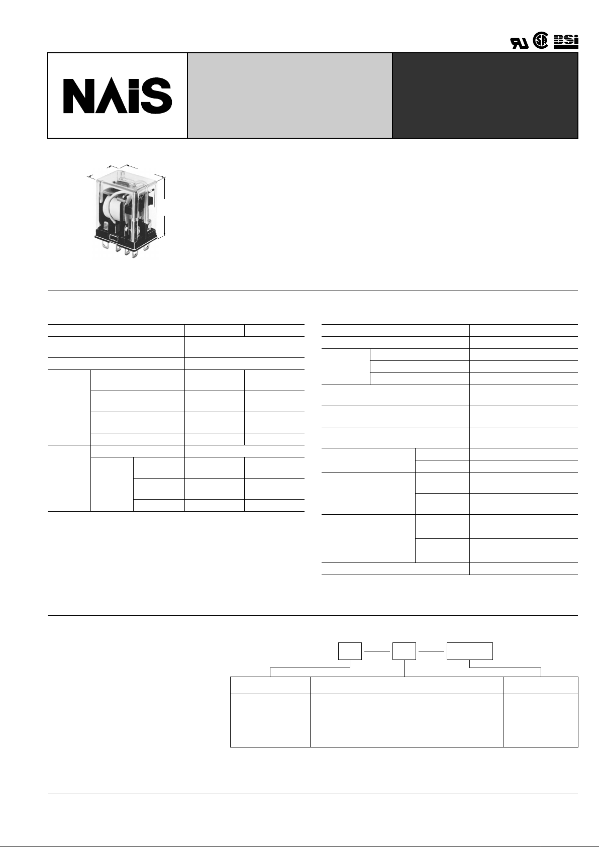
HL-RELAYS
15A (1C), 10 A (2C)
SPACE SAVING
POWER RELAY
TESTING
mm inch
27.2
1.071
35.4
1.394
20.8
.819
FEATURES
• High switching capacity in a compact size
1 Form C (15 A 125 V AC), 2 Form C (10 A 250 V AC)
• Rugged construction for tough applications
• Long life
Mechanical: Min. 10
8
operations (DC),
Min. 5 × 10
7
operations (AC)
Electrical: Min. 5 × 10
5
operations
SPECIFICATIONS
Contacts
Remarks
* Specifications will vary with foreign standards certification ratings.
*
1
Measurement at same location as "Initial breakdown voltage" section
*
2
Detection current: 10 mA
*
3
Excluding contact bounce time
*
4
Half-wave pulse of sine wave: 11ms; detection time: 10 µ s
*
5
Half-wave pulse of sine wave: 6ms
*
6
Detection time: 10 µ s
*
7
Refer to 5. Conditions for operation, transpor t and storage mentioned in
AMBIENT ENVIRONMENT (Page 61).
Characteristics (at 25 ° C 77 ° F, 50% Relative humidity)
Arrangement 1 Form C 2 Form C
Initial contact resistance, max.
(By voltage drop 6 V DC 1 A)
50 m Ω
Contact material Silver alloy
Rating
(resistive)
Nominal switching
capacity
15 A 125 V AC ,
10 A 250 V AC
10 A 250 V AC
Max. switching power
AC: 2,500 VA
DC: 90 W
AC: 2,500 VA
DC: 90 W
Max. switching voltage
250 V AC
30 V DC
250 V AC
30 V DC
Max. switching current 15 A 10 A
Expected
life
Mechanical (at 180 cpm) 5 × 10
7
(AC), 10
6
(DC)
Electrical
(resistive)
15 A 125 V
AC
5 × 10
5
—
10 A 250 V
AC
5 × 10
5
5 ×
10
5
3 A 30 V DC 5 × 10
5
5 ×
10
5
Max. operating speed 20 cpm
Initial insulation resistance*
1
Min. 100 M Ω (at 500 V DC)
Initial
breakdown
voltage*
2
Between contact sets 1,500 Vrms for 1 min.
Between open contacts 1,000 Vrms for 1 min.
Between contacts and coil 2,000 Vrms for 1 min.
Operate time (at nominal voltage)
Approx. 10 ms (DC type)
Approx. 10 ms (AC type)
Release time*
3
(without diode)
(at nominal voltage)
Approx. 5 ms (DC type)
Approx. 10 ms (AC type)
Temperature rise, max.
(at nominal voltage)
Max. 80 ° C
Shock resistance
Functional*
4
Min. 196 m/s
2
{20 G}
Destructive*
5
Min. 980 m/s
2
{100 G}
Vibration resistance
Functional*
6
10 to 55 Hz
at double amplitude of 1 mm
Destructive
10 to 55 Hz
at double amplitude of 2 mm
Conditions for operation, transport and storage*
7
(Not freezing and
condensing at low temperature)
Ambient
temperature
–50 ° C to +70 ° C
–58 ° F to +158 ° F
Humidity 5 to 85% R.H.
Unit weight Approx. 35 g 1.25 oz
TYPICAL
APPLICATIONS
Pow er station control equipment, refrigerators, building control equipment, office
machines, and medical equipment.
ORDERING INFORMATION
2HHLEx.
Contact arrangement
AC240V
Terminal arrangement Coil voltage
Note: Standard packing Carton: 20 pcs., Case: 200 pcs.
UL/CSA approved type is standard.
1: 1 Form C
2: 2 Form C
H: Plug-in
HP: PC board
HTM: Top mounting
L: Light emitting diode wired, plug-in
PL: Light emitting diode wired, PC board
AC 6, 12, 24, 48,
120, 240 V
DC 6, 12, 24, 48,
110 V
Page 2
HL
408
COIL DATA (at 20 ° C 68 ° F)
DC coils
AC coils (50/60 Hz), at 60 Hz
Coil voltage,
V DC
Pick-up voltage,
V DC (max.)
Drop-out voltage,
V DC (min.)
Max. allowable
voltage, V DC
Coil resistance,
Ω ( ±
10%)
Nominal coil
current, mA
Operating power, W
Nominal Minimum
6 4.8 0.6 6.6 40 150
0.90 0.58
12 9.6 1.2 13.2 160 75
24 19.2 2.4 26.4 650 37
48 38.4 4.8 52.8 2,600 18.5
110 88.0 11.0 121.0 10,000 10 1.0 0.64
Coil voltage,
V DC
Pick-up voltage,
V AC (max.)
Drop-out voltage,
V AC (min.)
Max. allowable
voltage, V AC
Nominal coil
current, mA
Operating power, VA
Nominal Minimum
6 4.8 1.8 6.6 200
1.20 0.77
12 9.6 3.6 13.2 100
24 19.2 7.2 26.4 50
48 38.4 14.4 52.8 25
110/120 96 36 132 10.9/11.9
220/240 176.0 66 242.0 6.0/6.5
Notes:
1. The range of coil current is ± 15% for AC (60 Hz), ± 10% for DC, at 20 ° C.
2. The rela y may be used in the range of 80% to 110% of the nominal coil
voltage. However, it is recommended that the rela y be used at 85% to
110% nominal voltage to take temporary voltage variations into consideration.
3. Each coil resistance of DC types is the measured value at a coil temperature of 20 ° C. Please allow a compensation of ± 0.4% resistance for
each coil temperature change of ± 1 ° C.
4. All AC 240 V types are rated for double coil voltages, both AC 220 V
and AC 240 V.
5. F or use with 220 or 240 V DC , connect a resistor , as suggested belo w ,
in series with the 110 V DC relay.
Voltage 1 Form C, 2 Form C
220 V DC
240 V DC
11 kW (5 W)
13 kW (5 W)
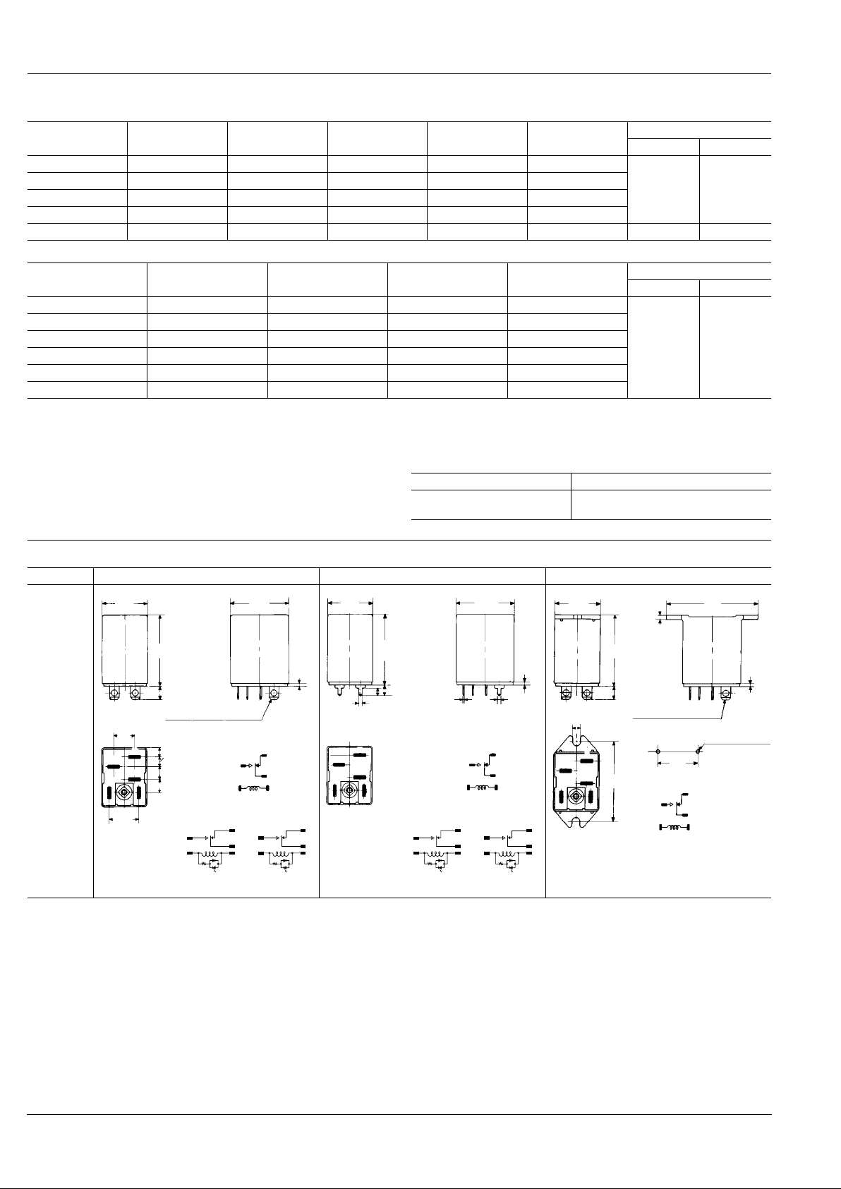
DIMENSIONS
mm inch
Plug-in PC board*
1
Top mounting
HL1
(1 Form C)
1.2
.047
Accepts Faston #187
Schematic
2
6
87
3
20.8
.819
27.2
1.071
6.35
.250
10
.394
3.95
.156
4.6
.181
6
.236
7.15
.281
35.4
1.394
14.2
.559
AC type DC type
8
7
(∼)
(∼)
3
2
6
8
7
(−)
(+)
3
2
6
20.8
.819
27.2
1.071
35.4
1.394
3
3
2
2
6
6
8
7
Schematic
1.2
.047
0.5
.020
1.5
.059
5
.197
3.5
.138
1.5
.059
78
AC type DC type
8
7
(∼)
(∼)
3
2
6
8
7
(−)
(+)
3
2
6
20.6
.811
43
1.693
3
3
2
6
87
2
6
8
7
Schematic
Accepts Faston #187
Mounting dimension
2-3.2 to 3.5 dia
2
.079
1.2
.047
2-.126 to .138 dia
6.35
.250
3.6
.142
35.4
1.354
37.6
1.480
37.6
1.480
Page 3

HL
409
Tolerance: ± 0.5 ± .020
HL2
(2 Form C)
Plug-in PC board*
1
Top mounting
20.8
.819
35.4
1.394
27.2
1.071
1.2
.047
6.35
.250
10
.394
14.2
.559
3.7
.146
4.7
.185
6
.236
7.3
.287
1
3
5
7
Accepts Faston #187
8
2
4
6
Schematic
AC type DC type
8
7
(∼)
(∼)
3
2
6
8
7
(−)
(+)
3
2
6
27.2
1.071
1.2
.047
0.5
.020
1.5
.059
20.8
.819
35.4
1.394
3.5
.138
1.5
.059
1
78
1
3
5
78
2
4
6
3
5
2
4
6
Schematic
5
.197
AC type DC type
8
7
(∼)
(∼)
3
2
6
8
7
(−)
(+)
3
2
6
20.6
.811
37.6
1.480
37.6
1.480
2
.079
43
1.693
1.2
.047
1
1
2
4
65
3
87
3
5
2
4
6
78
Schematic
Accepts Faston #187
Mounting dimension
2-3.2 to 3.5 dia.
2-.126 to .138 dia.
6.35
.250
3.6
.142
34.4
1.354
*
1
PC board pattern
Copper-side view
(HL1) (HL2)
5-2 dia.
5-.079 dia.
7.15
.281
17.75
.700
8.5
.335
14.2
.559
4.6
.181
6
.236
4
.158
4
.158
4
.158
10
.394
1.25
.049
1.25
.049
1.25
.049
R3
R2
8-2 dia.
8-.079 dia.
7.3
.287
18
.709
13.3
.524
14.2
.559
2
.079
10
.394
2
.079
R2
R2
Tolerance: ± 0.1 ± .004
ACCESSORIES
1.Plug-in terminal Socket
HL1-SS-K (with hold-down clip)
25.5
1.004
18.7
.736
11.2 .441
29.4
1.157
Accepts Faston #187
0.23
.009
4.75
.187
Panel cutout
25.8
1.016
21.6
.850
HL2-SS-K (with hold-down clip)
25.5
1.004
18.7
.736
11.2 .441
29.4
1.157
Accepts Faston #187
0.23
.009
4.75
.187
Panel cutout
25.8
1.016
21.6
.850
Plug-in terminal socket mount
Simply insert socket into panel hole and
push down as indicated to lock socket in
place.
Panel cutout for tandem mounting
Tolerance: ± 0.1 ± .004
1.0 to 2.0
.039 to .079 Panel thickness
25.8
1.016
8.9
.350
25.8
1.016
21.6
.850
21.6
.850
5.9
.232
Minimum
separation distance
mm inch
mm inch
Page 4

HL
410
3. Screw terminal socket for DIN rail assembly
HL2-SFD-K (with hold-down clip)
M3.5
Terminal screw
26±0.6
1.024±.024
28.6±0.6
1.126±.024
30±0.6
1.181±.024
8
.315
67±1
2.638
±.039
21.1±0.6
.831±.024
10±0.2
.394±.008
4.65
±0.2
.183
±.008
1.35
±0.1
.053
±.004
9.35±0.2
.368±.008
8.1±0.2
.319±.008
Schematic
21
43
65
87
Layout for tandem mounting
Tolerance: ± 0.1 ± .004
8
.315
26
1.024
26
1.024
30
1.181301.181
4
.158
33.5
1.319
67
2.638
Minimum separation in tandem mounting
2-M3.5 SCREW HOLES OR
2-4.2
±
0.1 DIA.
(Remark) Max. continuous current of all HL sockets is 10 A.
mm inch
For Cautions for Use, see Relay Technical Information (Page 48 to 76).
2. PC board terminal socket
HL1-PS-K
21.2
.835
16.2
.638
11.2
.441
0.23
.009
2.0
.079
1.0
.039
29.4
1.157
PC board pattern
15.3
.602
10
.394
5-2.4 dia.
5-.094 dia.
17.45
.687
12.75
.502
6.75
.266
HL2-PS-K
21.2
.835
16.2
.638
11.2
.441
0.23
.009
2.0
.079
1.0
.039
29.4
1.157
PC board pattern
15.3
.602
10
.394
8-2.4 dia.
8-.094 dia.
17.45
.687
12.75
.502
6.75
.266
Layout for tandem mounting
(2 Form C)
Tolerance: ±0.1 ±.004
10
.394
23.2
.91310.394
(6.6)
(.260)
(5.3)
(.209)
17.45
.687
17.45
.687
17.25
.679
15.3
.602
7.9
.311
15.3
.602
2.4 dia.
.094 dia.
9/1/2000 All Rights Reserved, © Copyright Matsushita Electric Works, Ltd.
Go To Online Catalog
 Loading...