

October 1998
Semiconductor
HI1866
See HI3086
NOT RECOMMENDED FOR NEW DESIGNS
6-Bit, 140 MSPS, Flash A/D Converter
Features
• Ultra-High Speed Operation with Maximum
Conversion Rate. . . . . . . . . . . . . . . . . . . . . . . 140 MSPS
[ /Title (HI1866)
• Low Input Capacitance . . . . . . . . . . . . . . . . . . . . . . . 7pF
/Subject (6-Bit, 140 MSPS, Flash A/D Converter)
• Wide Analog Input Bandwidth . . . . . . . . . . . . . 210MHz
/Author ()
• Low Power Consumption . . . . . . . . . . . . . . . . . .325mW
/Keywords (Harris Semiconductor, RGB, Video, Flat
• Low Error Rate
Panel, LCD)
• Excellent Temperature Characteristics
/Creator ()
• 1:2 Demultiplexed Output (TTL Level)
/DOCINFO pdfmark
• Direct Replacement for Sony CXA1866
[ /PageMode /UseOutlines
Applications
/DOCVIEW pdfmark
• LCD Panels
• Magnetic Recording (PRML)
• Communications (QPSK, QAM)
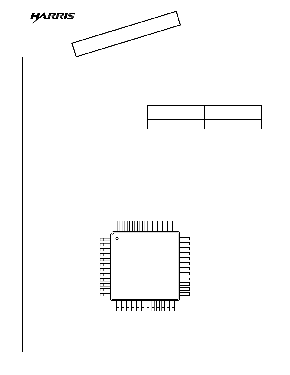
Pinout
HI1866
(MQFP)
TOP VIEW
Description
HI1866 is a 6-bit, high-speed, flash A/D converter capable of
digitizing analog signals at the maximum rate of 140 MSPS.
The digital input level is compatible with the ECL
100K/10KH/10K.
Ordering Information
PART
NUMBER
HI1866JCQ -20 to 75 48 Ld MQFP Q48.12x12-S
TEMP.
RANGE (oC) PACKAGE PKG. NO.
DGND3
P2D0 (LSB)
P2D1
P2D2
P2D3
P2D4
P2D5 (MSB)
DGND3
DV
CC2
NC
DCLK
NDCLK
CC2
DV
DV
1
2
3
4
5
6
7
8
9
10
11
12
13 14 15 16
EE
NC
AV
CC1
DGND1
DGND2
RB
RBS
V
V
EE
DV
AGND
CC2
DV
NC
EE
DGND3
DV
IN
V
AGND
DGND2
DGND1
RT
RTS
V
V
DV
EE
AV
CC1
373839404142434445464748
2423222120191817
36
35
34
33
32
31
30
29
28
27
26
25
DV
NC
CC2
DGND3
P1D5 (MSB)
P1D4
P1D3
P1D2
P1D1
P1D0 (LSB)
DGND3
DV
CC2
INV
CCLK
NCCLK
CAUTION: These devices are sensitive to electrostatic discharge. Users should follow proper IC Handling Procedures.
Copyright
© Harris Corporation 1997
4-1
File Number 4108.2
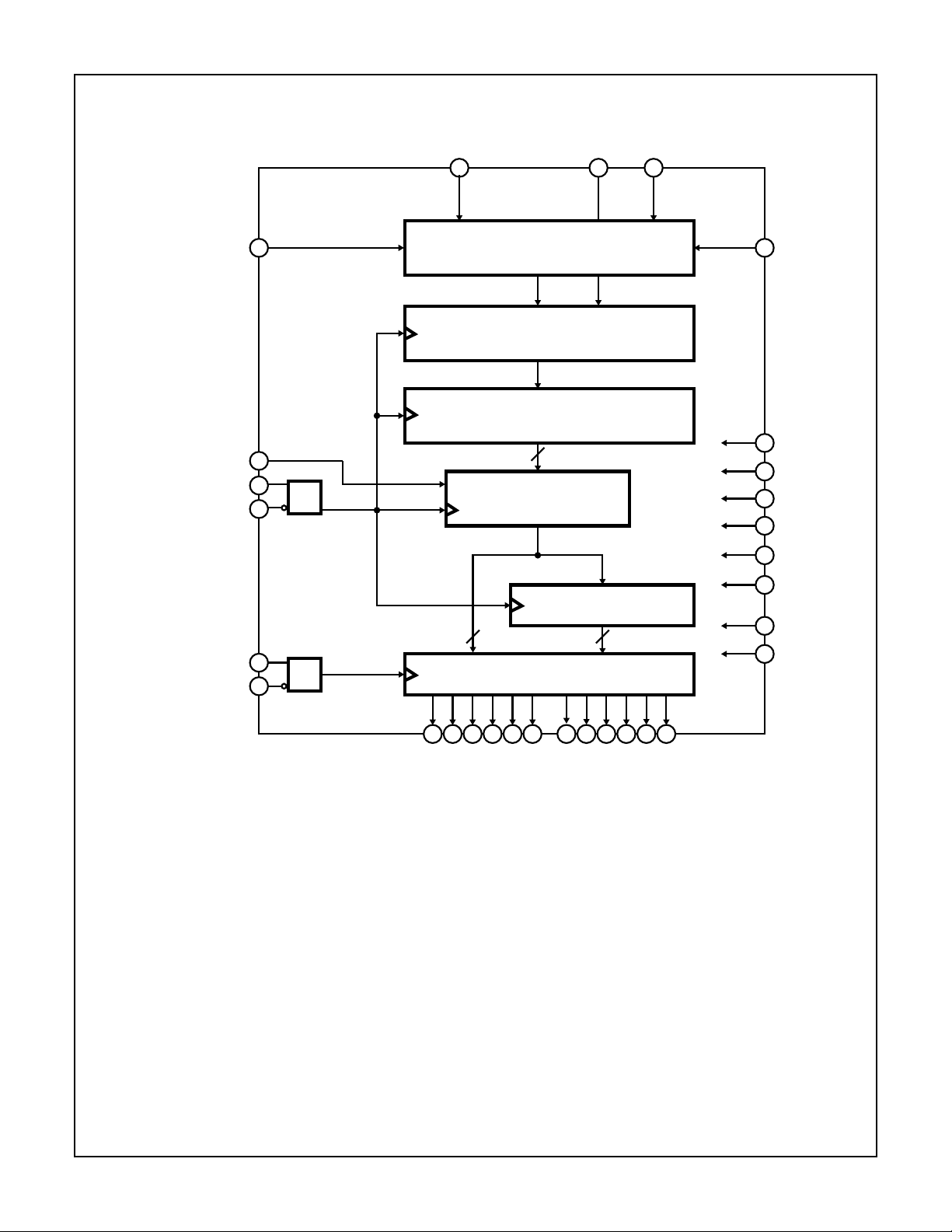
Functional Block Diagram
HI1866
V
RTS
INV
CCLK
NCCLK
DCLK
NDCLK
V
RBS
16 21 V
27
26
CD
25
11
CD
12
REFERENCE RESISTANCE CHAIN
COMPARATOR
6-BIT LATCH
CLATCH A
TTLOUT
6
V
IN
19 2215
CLATCH B
66
V
RTS
41
23
20
46
45
42
47
48
RT
D
VEE
A
VEE
AGND
DGND1
DGND2
DGND3
DV
CC1
DV
CC2
CD: CLOCK DRIVER
7 6 5 4 3 2 35 34 33 32 31 30
P2D4
P2D3
P2D2
P2D5 (MSB)
P2D1
P2D0 (LSB)
P1D4
P1D3
PD15 MSB)
P1D2
P1D1
P1D0 (LSB)
4-2
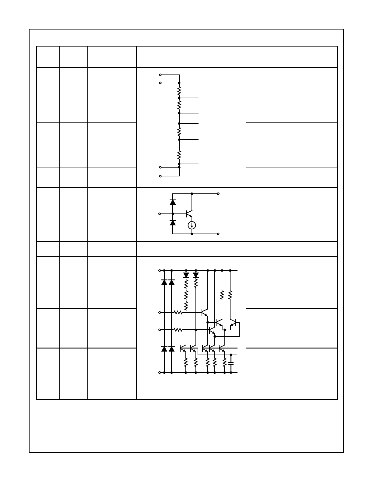
Pin Descriptions
PIN NO. SYMBOL I/O
21 V
22 V
16 V
15 V
RT
RTS
RB
RBS
HI1866
TYPICAL
VOLTAGE
LEVEL EQUIVALENT CIRCUIT DESCRIPTION
I 0V Top reference voltage input (= 0). This is
O0V V
I -2V Bottom reference voltage input (= -2V).
O -2V VRB sense output. This is the voltage
V
V
V
RTS
RBS
V
RB
RT
COMPARATOR 1
COMPARATOR 2
COMPARATOR 31
COMPARATOR 32
COMPARATOR 63
the top reference voltage supplied to the
internal resistance chain. The external
input can be set in accordance with the
peak value on the plus side of the input
analog signal amplitude.
sense output. This is the voltage
RT
sense pin for VRT.
This is the bottom reference voltage
supplied to the internal resistance
chain. The external input can be set in
accordance with the peak value on the
minus side of the input analog signal
amplitude.
sense pin for VRB.
19 V
IN
IV
RTS
V
RBS
to
AGND
V
IN
A
VEE
Analog input. The input range is 2V
P-P
26 CCLK I ECL CCLK clock input. This is the conversion
clock, and is an ECL level input.
25 NCCLK I ECL CCLK inversion clock input. This is an
DGND1
ECL level input. When left open, this
input goes to the ECL threshold potential
(-1.3V). Only CCLK input can be used for
R
R
R
500
11 DCLK I ECL DCLK clock input. This is the 1:2 DMPX
CCLK
(DCLK)
NCCLK
(NDCLK)
R
500
operation with the NCCLK input left
open, but complementary input is
recommended to attain fast and stable
operation.
latch clock; input a clock of1/2 frequency
of CCLK. Data is output from DMPX port
1 and port 2 synchronously with the
rising edge of this signal. This is an ECL
level input.
12 NDCLK I ECL DCLK inversion clock input. This is an
RR
D
VEE
ECL level input. When left open, this
1.3V
input goes to the ECL threshold potential
(-1.3V). Only DCLK input can be used for
operation with the NDCLK input left
open, but complementary input is
recommended to attain fast and stable
operation.
.
4-3
HI1866
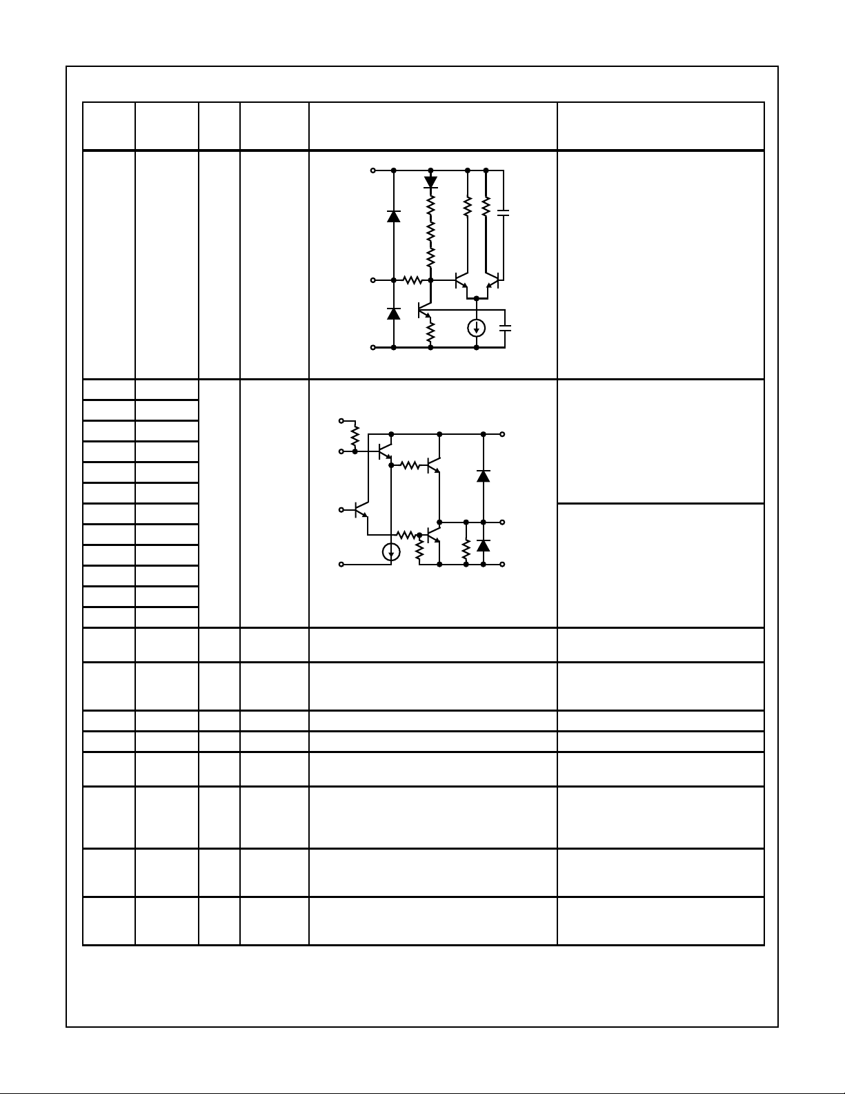
Pin Descriptions
(Continued)
TYPICAL
VOLTAGE
PIN NO. SYMBOL I/O
27 INV I ECL Digital output polarity inversion input.
LEVEL EQUIVALENT CIRCUIT DESCRIPTION
DGND1
This is an ECL level input. This input
inverts the polarity of the digital outputs
R
R
1.3V
P1D0 to P1D5, and P2D0 to P2D5.
(Refer to the Output Code Table.) When
left open, this signal is maintained at the
low level.
R
500
INV
1.3V
D
R
VEE
30 P1D0 O TTL These pins are for the 6 bits of digital
31 P1D1
32 P1D2
DV
CC1
DV
CC2
output data for DMPX port 1. P2D5 is the
MSB, and P2D0 is the LSB. These are
TTL levels outputs.
33 P1D3
34 P1D4
35 P1D5
2 P2D0 These pins are for the 6 bits of digital
3 P2D1
100K
4 P2D2
5 P2D3
P1D0 TO D5
P2D0 TO D5
DGND3DGND2
output data for DMPX port 2. P2D5 is the
MSB, and P2D0 is the LSB. These are
TTL level outputs.
6 P2D4
7 P2D5
38, 47 DVCC1 - +5.0V +5V power supply for TTL level internal
circuit.
9, 28,
37, 43,
DVCC2 - +5.0V +5V power supply for TTL level output
buffers (P1D0 to P2D5).
48
39, 46 DGND1 - 0V Ground for DV
40, 45 DGND2 - 0V Ground for DV
1, 8, 29,
DGND3 - 0V Ground for DV
digital circuit.
EE
digital circuit.
CC1
digital circuit.
CC2
36, 42
17, 20 AGND - 0V Ground for A VEE analog circuit. Used as
the ground for the comparator input
buffers, latches, etc. Separated from
DGND.
41, 44 DV
EE
- -5.2V -5.2V power supply for digital circuit.
Connected internally with AVEE.
(Resistance is 4Ω to 6Ω.)
14, 23 AV
EE
- -5.2V -5.2V power supply for analog circuit.
Connected internally with DVEE.
(Resistance is 4Ω to 6Ω.)
4-4

HI1866
Absolute Maximum Ratings Thermal Information
Supply Voltage (AVEE, DVEE) . . . . . . . . . . . . . . . . . . . . -7V to 0.5V
(DVCC) (Note 2). . . . . . . . . . . . . . . . . . . .0.5V to 7.0V
Reference Voltage (VRT, VRB). . . . . . . . . . . . . . . . . . . -2.7V to 0.5V
(VRT - VRB). . . . . . . . . . . . . . . . . . . . . . . . .2.5V
Analog Input Voltage (VIN) . . . . . . . . . . . . . . . . . . . . . . -2.7V to 0.5V
Digital Input Voltage (DIN) (Note 3) . . . . . . . . . . . . . . . -4.0V to 0.5V
( CCLK–NCCLK , DCLK–NDCLK ) . . . .2.5V
Digital Output Current (ID0 to ID6) . . . . . . . . . . . . . -30mA to +30mA
Storage Temperature (T
) . . . . . . . . . . . . . . . . . . -65oC to 150oC
STG
Ambient Operating Temperature (TA). . . . . . . . . . . . . -20oC to 75oC
Allowable Power Dissipation (PD). . . . . . . . . . . . . . . . . . . . . 750mW
Recommended Operating Conditions
Supply Voltage MIN TYP MAX
AVEE, DVEE . . . . . . . . . . . . . . . . . . . . . . . -5.5V -5.2V -4.75V
AVEE - DVEE. . . . . . . . . . . . . . . . . . . . . . .-0.05V 0V 0.05V
AGND - DGND (Note 4) . . . . . . . . . . . . . -0.05V 0V 0.05V
DVCC(Note 5). . . . . . . . . . . . . . . . . . . . . . 4.75V 5.0V 5.25V
Temperature Range (TA) . . . . . . . . . . . . . . . -20oC- 75oC
CAUTION: Stresses above those listed in “Absolute Maximum Ratings” may cause permanent damage to the device. This is a stress only rating and operation
of the device at these or any other conditions above those indicated in the operational sections of this specification is not implied.
NOTES:
1. θJA is measured with the component mounted on an evaluation PC board in free air.
2. DVCC = DV
3. DIN = CCLK, NCCLK, DCLK, NDCLK, INV.
4. DGND = DGND1, DGND2, DGND3.
5. Refer to Timing Chart 1 for t
CC1
, DV
CC2
.
, t
PWH
.
PWL
Thermal Resistance (Typical, Note 1) θJA (oC/W)
MQFP Package. . . . . . . . . . . . . . . . . . . . . . . . . . . . 95
Maximum Junction Temperature. . . . . . . . . . . . . . . . . . . . . . .150oC
Maximum Storage Temperature Range (T
) . . . -65oC to 150oC
STG
Maximum Lead Temperature (Soldering 10s). . . . . . . . . . . . .300oC
(Lead Tips Only)
Reference Input Voltage MIN TYP MAX
VRT . . . . . . . . . . . . . . . . . . . . . . . . . . . . . -0.1V 0V 0.1V
VRB . . . . . . . . . . . . . . . . . . . . . . . . . . . . . -2.2V -2.0V -0.8V
Analog Input Voltage (VIN) . . . . . . . . . . . . . V
RB
To V
RT
Digital Input Voltage, DIN (H) . . . . . . . . . . . -1.1V - -
DIN (L) - - -1.5V
CCLK, NCCLK Frequency (f
DCLK, NDCLK Frequency (f
CCLK, NCCLK Duty (D
DCLK, NDCLK Duty (D
CCLK
DCLK
CCLK-DCLK Time Difference (t
)(MHz) . . - - 140
CCLK
)(MHz) . . - - 70
DCLK
)(%) . . . . . . . . 40 50 60
)(%) . . . . . . . . 40 50 60
)(ns). . . . -t
DCD
PWL
+ 2 0 t
PWH
+ 1
Electrical Specifications T
= 25oC, AVEE = DVEE = -5.2V, DVCC = 5V, VRT = 0V, VRB = -2V
A
PARAMETER SYMBOL TEST CONDITIONS MIN TYP MAX UNITS
Resolution, n n - 6 - bits
DC CHARACTERISTICS
Integral Linearity Error E
Differential Linearity Error E
IL
DL
No Missing Code - Guar-
fC = 140MHz - - ±0.2 LSB
fC = 140MHz - - ±0.2 LSB
--
anteed
ANALOG INPUT
Analog Input Capacitance C
Analog Input Resistance R
Input Bias Current I
IN
IN
IN
VIN = -1V_0.7V
, DC - 7 - pF
RMS
-2V ≤ VIN≤ 0V 200 - - KΩ
-2V ≤ VIN≤ 0V - - 110 µΑ
REFERENCE INPUT
Reference Resistance R
Reference Resistance Current I
Offset Voltage V
RT
V
RB
REF
REF
E
E
OB
OT
- 225 - Ω
-9-mA
0 - 25 mV
- - 25 mV
DIGITAL INPUT
Logic High Level V
IH
-1.13 - - V
4-5

HI1866
Electrical Specifications T
= 25oC, AVEE = DVEE = -5.2V, DVCC = 5V, VRT = 0V, VRB = -2V (Continued)
A
PARAMETER SYMBOL TEST CONDITIONS MIN TYP MAX UNITS
Logic Low Level V
Logic High Current I
Logic Low Current I
IL
IH
IL
VIH = -0.8V 0 - 50 µA
VIL = -1.6V -50 - 50 µA
- - -1.50 V
Input Capacitance - 3.5 - pF
SWITCHING CHARACTERISTICS
Maximum Conversion Frequency f
Aperture Jitter t
Sampling Delay t
C
AJ
DS
Error Rate 1E-9 TPS (Note 1) 140 - - MSPS
- 5.0 - ps
- 1.0 - ns
DIGITAL OUTPUT
Logic High Level V
Logic Low Level V
Output Delay t
Output Rising Time t
Output Falling Time t
OH
OL
DO
r
f
I
= -2mA 2.7 - - V
OUT
I
= 1mA - - 0.5 V
OUT
ZL = 25pF 2.0 - 8.0 ns
ZL = 25pF, 0.5V to 2.4V - 1.2 - ns
ZL = 25pF, 0.5V to 2.4V - 1.2 - ns
DYNAMIC CHARACTERISTICS
Analog Amplitude Input Bandwidth F
INB
VIN = 2V
P-P
,
210 - - MHz
Peak-to-Peak Value = 3dB Down
Input Frequency
S/N Ratio SNR1
SNR2
SNR3
Error Rate fC = 140MHz, Error > 4 LSB - -10
fC = 140MHz, fIN = 1MHz
fC = 140MHz, fIN = 35MHz
fC = 140MHz, fIN = 70MHz
-36
34
32
-9
-dB
- TPS
(Note 1)
POWER SUPPLY
Supply Current I
Power Consumption P
I
CC
EE
D
DVCC = +5V
AVEE = DVEE = -5.2V
-
-60
20
-40
32
-
- 325 - mW
NOTE:
1. TPS: Times Per Sample
dB
dB
mA
mA
Output Code Table
DINV: 1 INV:0
V
IN
STEP
D5 D0 D5 D0
0V 0 000000 111111
1 000001 111110
•
•
•
-1V 31 011111 100000
32 100000 011111
•
•
•
62 111110 000001
-2V 63 111111 000000
NOTE: VRT = 0V, VRB = -2V.
4-6
•
•
•
•
•
•

Timing Diagrams
t
DS
V
IN
CCLK
N - 1
t
N N + 1 N + 2
r
t
f
-1.1V
-1.5V
HI1866
D
CCLK
N + 3
N + 4
t
PWH
t
PWL
-1.3V
NCCLK
DCLK
NDCLK
P1D0-5
P2D0-5
t
DCD
t
DO
-1.3V
D
t
f
t
DO
2.0V
1.0V
2.0V
1.0V
t
r
-1.1V
-1.5V
N - 2N - 4
DCLK
-1.3V
-1.3V
N
N + 1N - 1N - 3
FIGURE 1. TIMING CHART 1
4-7

HI1866
Timing Diagrams
V
CCLK
DCLK
IN
COMPARATOR 6-BIT LATCH CLATCHA CLATCHB
V
IN
CCLK
(Continued)
6
N - 1 N N + 1 N + 2
66
TTL
OUT
N + 3
66
N + 4 N + 5
TTL
OUT
6
P1D0 TO D5
P2D0 TO D5
COMPARATOR
(MASTER)
COMPARATOR
(SLAVE)
6-BIT LATCH
CLATCHA
CLATCHB
DCLK
TTL
(P2D0 TO D5)
OUT
●
N - 1
N - 2 N - 1 N N + 1
N - 4 N - 3 N - 2 N - 1 N N + 1 N + 2
N N + 1 N + 2 N + 3 N + 4 N + 5
●
●
●
N - 3 N - 1 N + 1
N + 2 N + 3 N + 4
N + 3N + 2N + 1NN - 1N - 2N - 3
N + 5N + 4N + 3N + 2N + 1NN - 1
TTL
(P1D0 TO D5)
OUT
NN - 2N - 4
FIGURE 2. TIMING CHART 2
4-8

Test Circuits
HI1866
2V
f
P-P
SIGNAL
SOURCE
CLK
-1kHz
4
SIN WAVE
SIGNAL
SOURCE
f
CLK
V
IN
AMP
C
CLK
DUT
HI1866
D
1
CLK
/
2
6
6
LATCH
+
DATA 4
FIGURE 3. MAXIMUM CONVERSION RATE TEST CIRCUIT
+V
DVM
V
IN
-
+
DUT
HI1866
C
CLKDCLK
S1
S2
(P1D0 TO D5)
6
6
(P2D0 TO D5)
“0”
-V
COMPARATOR
SW
CONTROLLER
S1: NON WHEN A< B
S2: ON WHEN A > B
A < B A > B
B6
A6
TO
TO
B1
A1
B0
A0
LATCH
“1”
A
B
6
6
COMPARATOR
A > B
BUFFER
000000
TO
111110
PULSE
COUNTER
FIGURE 4. INTEGRAL/DIFFERENTIAL LINEARITY ERROR TEST CIRCUIT
4-9

HI1866
Test Circuits
(Continued)
37
38
39
40
41
42
43
44
45
46
47
48
DGND3
DV
CC2
DV
CC1
DGND1
DGND2
DV
EE
DGND3
DV
CC2
DV
EE
DGND2
DGND1
DV
CC1
DV
CC2
P1D5
DGND3
P2D0
P1D4
P2D1
3233343536 262728293031
P1D3
P2D2
P1D2
HI1866
P2D3
P1D1
P2D4
P1D0
P2D5
DV
DGND3
CC2
DV
DGND3
CC2
INV
CCLK
AGND
AGND
DCLK
121110987651234
25
NCCLK
AV
EE
V
RTS
V
RT
V
IN
V
RB
V
RBS
AV
EE
NDCLK
24
23
22
21
20
19
18
17
16
15
14
13
I
IN
A
-1.0V
-2.0V
I
CC
A A
+5.0V -5.2V
I
EE
FIGURE 5. CURRENT CONSUMPTION/ANALOG INPUT BIAS TEST CIRCUIT
6
LOGIC
ANALYZER
6
SW
SIGNAL SOURCE 1
∅: VARIABLE
FREQUENCY
LOCK
SIGNAL SOURCE 2
V
ECL
BUFFER
IN
HI1866
CCLK DCLK
1024
SAMPLES
FIGURE 6. SAMPLING DELAY/APERTURE JITTER TEST CIRCUIT
4-10

Typical Performance Curves
HI1866
-30
VEE = -5.2V, VCC = +5V
-35
-40
-45
CURRENT CONSUMPTION (mA)
-50
-25 0 25
AMBIENT TEMPERATURE (
I
CC
I
EE
50 75
o
C)
FIGURE 7. CURRENT CONSUMPTION vs AMBIENT
TEMPERA TURE
0.40
VEE = -5.2V, VCC = 5V, I
0.38
0.36
0.34
OUT
= 1mA
25.0
22.5
20.0
17.5
15.0
3.6
VEE = -5.2, VCC = 5V, I
3.5
3.4
3.3
3.2
DIGITAL OUTPUT LEVEL (V)
CURRENT CONSUMPTION (mA)
3.1
-25 0 25
FIGURE 8. VOH vs AMBIENT TEMPERATURE
38
36
34
32
30
SNR (dB)
28
= -2mA
OUT
AMBIENT TEMPERATURE (
50 75
o
C)
0.32
DIGITAL OUTPUT LEVEL (V)
0.30
-25 0 25
AMBIENT TEMPERATURE (oC)
50 75
26
24
CCLK = 140MHz, DCLK = 70MHz
22
1 10 100
INPUT FREQUENCY (MHz)
FIGURE 9. VOL vs AMBIENT TEMPERATURE FIGURE 10. SNR vs INPUT FREQUENCY
6.5
CCLK = 140MHz, DCLK = 70MHz
6.0
5.5
5.0
4.5
4.0
EFFECTIVE BIT NUMBER (BITS)
3.5
110
INPUT FREQUENCY (MHz)
100
-20
CCLK = 140MHz, DCLK = 70MHz
-30
-40
3ND HARMONIC DISTORTION (dB)
-50
-60
2ND, 3RD HARMONIC DISTORTION (dB)
-70
110
2ND HARMONIC DISTORTION (dB)
INPUT FREQUENCY (MHz)
100
FIGURE 11. EFFECTIVE BIT NUMBER vs INPUT FREQUENCY FIGURE 12. 2ND, 3RD HARMONIC DISTORTION vs INPUT
FREQUENCY
4-11

Notes on Operation
HI1866
The HI1186 is a high speed A/D converter with ECL level
logic input and demultiplexed TT level output. Take notice of
the following to ensure optimum performance from this IC.
Power Supply and Grounding
Grounding has a profound influence on converter
performance. The higher the frequency is, the more important the way of grounding becomes.
The ground pattern should be as large as possible. It is
recommended to make the power supply and ground
patterns wider at an inner layer using the multi-layer board.
To prevent interference between the AGND and DGND patterns and between the AV
and DVEE lines, make sure the
EE
respective patterns are separated. To prevent a DC offset in
the power supply pattern, connect the AV
and DVEE lines
EE
at one point each via a ferrite-bead filter. Shorting analog
and digital ground patterns in one place immediately under
the A/D converter improves A/D converter performance.
Ground the power supply pins (AV
, DVEE, DVCC) as
EE
close to each pin as possible with a 0.1µF or larger ceramic
chip capacitor. (Connect the AV
DV
to DGND, and DVCC to DGND.)
EE
pin to the AGND pattern,
EE
Analog Input
Make the connection between the V
pin and the analog
IN
input source as short as possible.
There is a slight offset voltage at reference voltage pins V
RT
and VRB. If it presents no problem in the application, the
voltage can be applied directly. However, if the reference
voltage is to be set precisely, apply it via a feedback circuit
created, using the V
Make adequate bypass for high frequency noise at V
V
. The VRT pin is normally connected to AGND on the
RB
board. Bypass the V
and V
RTS
pin to the AGND pattern with a 0.1µF
RB
RBS
pins.
RT
and
or larger ceramic chip capacitor as short as possible. The
10µF tantalum capacitor connected to V
in the Application
RB
Circuit is to stop oscillation in the reference voltage
generation circuit.
Digital Input
Noise at the INV pin may cause misoperation of which the
cause is extremely hard to identify. If it is okay for the set
voltage lev el to be lo w only, leave the pin open. If a high le vel
voltage has to be input, bypass the INV pin to DGND with an
about 0.1µF ceramic chip capacitor as short as possible. It is
recommended that high level input v oltage is about -0.5V to -
1.0V, and low level input voltage is about -1.6V to -2.5V.
When inputting a high level v oltage, a v oid connecting directly
to DGND.
The HI1186 has input pins for two clocks: CCLK and DCLK.
For CCLK, which is used for the internal comparator, input
an ECL level clock with up to the maximum conversion frequency. For DCLK, which is used for the multiplex output,
input an ECL level clock with a rate half that of CCLK. Take
notice of the timing between CCLK and DCLK.
It is recommended that differential signals be input to the
clock input pins CCLK, NCCLK, DCLK and NDCLK. The A/D
converter can be driven only by the clock input pins CCLK
and DCLK, but there is a risk of unstable characteristics at
maximum speeds.
If the NCCLK and NDCLK pins are not used, bypass these
pins to DGND with an about 0.1µF capacitor. In this time,
about -1.3V voltage is generated at the NCCLK and NDCLK
pins. However, this is too weak to be used as threshold voltage V
; it can not directly drive even one ECL input load.
BB
The clock duty cycle is designed for use at 50%. Any
diversion from this percentage will have a slight effect on the
maximum performance of the A/D converter, but there is no
great need for adjustment.
Digital Output
P1D0 (LSB) to P1D5 (MSB), and P2D0 (LSB) to P2D5
(MSB) are demultiplex digital outputs (2 systems), and are
output using the DCLK timing. The polarity of the output data
can be inverted using the INV signal.
4-12

Typical Application Circuit
HI1866
(TTL) P2D0
(TTL) P2D1
(TTL) P2D2
(TTL) P2D3
(TTL) P2D4
(TTL) P2D5
1
2
3
4
5
6
7
8
9
10
11
12
DV
DGND3
P2D0
P2D1
P2D2
P2D3
P2D4
P2D5
DGND3
DV
CC2
DCLK
NCLK
CC2DVCC1
EE
AV
DGND1
DGND2
RBSVRB
V
4445464748 383940414243
EE
DV
HI1866
AGND
CC2
DV
EE
DV
DGND3
VINAGND
DGND2
RT
V
DGND1
RTS
V
37
CC1DVCC2
DV
DGND3
P1D5
P1D4
P1D3
P1D2
P1D1
P1D0
DGND3
DV
CCLK
NCCLK
EE
AV
242322212019181713 14 15 16
CC2
INV
DGND
36
35
34
33
32
31
30
29
28
27
26
25
ONE POINT
SHORTING
P1D5 (TTL)
P1D4 (TTL)
P1D3 (TTL)
P1D2 (TTL)
P1D1 (TTL)
P1D0 (TTL)
INV (ECL LEVEL)
-5.2V
CAPACITORS, IF NOT SPECIFIED,
ARE 0.1µF CERAMIC CHIP CAPACITORS.
+5.0V
-
+
VRB -5.2V
10µF
TANTALUM
CAPACITOR
1
/2 CLK
ANALOG INPUT
V
AGND
RTS
ECL
BUFFER
CLK (ECL LEVEL)
4-13
 Loading...