

Page 1
422
HG-RELAYS
20 AMP POWER RELAY
36
1.417
56
2.205
a
mm inch
a
HG2 34.0 1.339
HG3 50.0 1.969
HG4 68.0 2.667
FEATURES
•
Large capacity — 20 A 250 V A C resistive and 1.5 kW 3 phase
220 V AC motor loads
• High contact reliability after long use
• Usable with direct soldering,
quick-connect and plug-in terminals. (.250)
SPECIFICATIONS
Contacts
Expected life (min. operations)
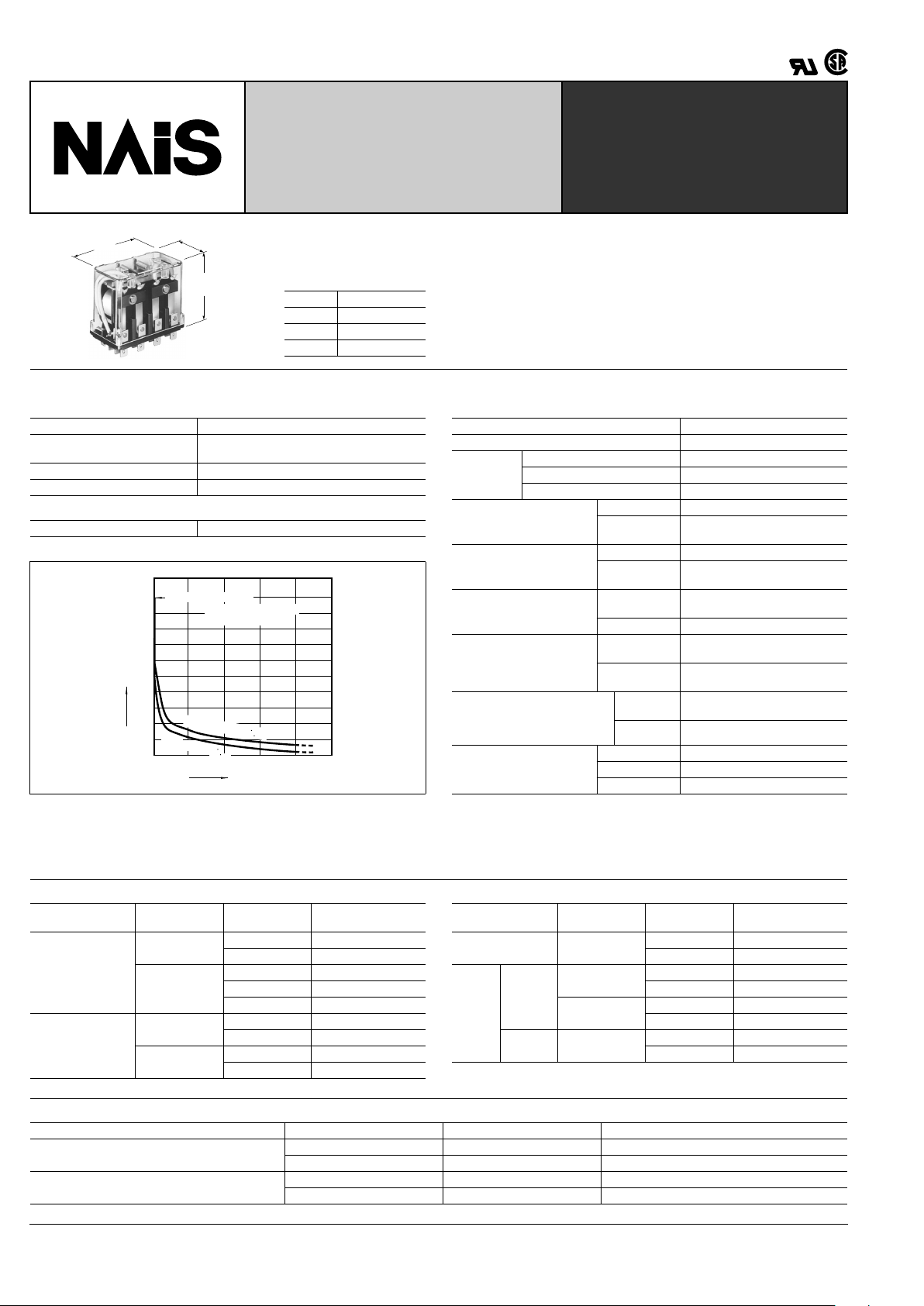
Life curve for AC types
Characteristics (at 60 Hz, 20 ° C 68 ° F)
Arrangement 2 Form C, 3 Form C, 4 Form C
Initial contact resistance, max.
(By voltage drop 6 V DC 1A)
15 m
Ω
Contact material Silver alloy
Nominal switching capacity 20 A 250 V AC (resistive)
Mechanical (at 180 cpm) AC type: 10
7
, DC type: 10
6
5101520
0
100
200
300
400
500
600
700
800
900
1,000
Load current, A
Operations, ×10
4
125 V AC cosϕ = 1
2
5
0
V
A
C
c
o
s
ϕ
=
1
Mechanical life : 10
7
Operating frequency:
180 op./min.
Maximum operating speed 20 cpm
Initial insulation resistance*
1
Min. 100 M Ω at 500 V DC
Initial
breakdown
voltage*
2
Between open contacts 2,000 Vrms for 1 min.
Between contacts sets 2,000 Vrms for 1 min.
Between contacts and coil 2,000 Vrms for 1 min.
Operate time*
3
(approx.)
(at nominal voltage)
2 Form C type 15 ms
3 Form C &
4 Form C type
25 ms
Release time
(without diode)*
3
(approx.)
(at nominal voltage)
2 Form C type 15 ms
3 Form C &
4 Form C type
25 ms
Shock resistance
Functional*
4
98 m/s
2
{10 G} (except for the
contact moving direction)
Destructive*
5
980 m/s
2
{100 G}
Vibration resistance
Functional*
6
58.8 m/s
2
{6 G}, 10 to 55 Hz
at 1 mm double amplitude
Destructive
117.6 m/s
2
{12 G}, 10 to 55 Hz
at 2 mm double amplitude
Conditions for operation,
transport and storage*
7
(Not freezing and condensing
at low temperature)
Ambient
temp.
–50
°
C to +40 ° C
–58
°
F to +104 ° F
Humidity 5 to 85% R.H.
Unit weight
2 Form C type Approx. 130 g 4.59 oz
3 Form C type Approx. 185 g 6.53 oz
4 Form C type Approx. 240 g 8.47 oz
Remarks
* Specifications will vary with foreign standards certification ratings.
*
1
Measurement at same location as "Initial breakdown voltage" section
*
2
Detection current: 10 mA
*
3
Excluding contact bounce time
*
4
Half-wave pulse of sine wave: 11ms; detection time: 10 µ s
*
5
Half-wave pulse of sine wave: 6ms
*
6
Detection time: 10 µ s
*
7
Refer to 5. Conditions for operation, transport and storage mentioned in
AMBIENT ENVIRONMENT (Page 61).
Electrical life with AC load
Note: In case of an electromagnet or exiting coil load (solenoid, etc.), the value of the motor or lamp load is applicable.
AC load Voltage, V AC Current, A
Expected life
(min. operations)
Resistive
(cos
ϕ
]
1)
125
20 5
×
10
5
15 7.5 × 10
5
250
20 2
×
10
5
15 5 × 10
5
10 7.5 × 10
5
Inductive
(cos
ϕ
]
0.4)
125
15 2
×
10
5
10 5 × 10
5
250
10 2
×
10
5
7.5 5 × 10
5
AC load Voltage, V AC Capacity, kW
Expected life
(min. operations)
Lamp 125
0.5 2
×
10
5
0.3 5 × 10
5
Motor
Single
phase
125
0.75 2
×
10
5
0.4 5 × 10
5
250
0.75 2
×
10
5
0.4 5 × 10
5
Three
phase
250
1.5 2
×
10
5
0.75 5 × 10
5
Electrical life with DC load
Note: For DC inductive load, use of an arc extinguishing circuit is recommended.
DC load Voltage, V DC Current, A Expected life (min. operations)
Resistive
24 15 5
×
10
5
125 0.8 5 × 10
5
Inductive (L/R
]
7 ms)
24 10 5
×
10
5
125 0.4 5 × 10
5
Page 2
HG
423
TYPICAL
APPLICATIONS
Industrial machinery, machine tools, food
processing and packing machines, office
machines, transportation equipment and
amusement devices.
ORDERING INFORMATION
Ex. HG 2 AC 240 V
Contact arrangement
(Note) Standard packing Carton: HG2 20 pcs.
HG3, HG4 10 pcs.
UL/CSA approved type is standard.
2: 2 Form C
3: 3 Form C
4: 4 Form C
Coil voltage
AC 6, 12, 24, 48, 115, 220, 240 V
DC 6, 12, 24, 48, 110, 200 V
Case: HG2 100 pcs.
HG3, HG4 50 pcs.
TYPES AND COIL DATA
DC TYPES at 20 ° C 68 ° F
AC TYPES (50/60 Hz) at 60 HZ, 20 ° C 68 ° F
Type Part No.
Nominal coil
voltage, V DC
Pick-up
voltage,
V DC (max.)
Drop-out
voltage,
V DC (min.)
Max.
allowable,
V DC voltage
Coil
resistance,
Ω ( ±
10%)
Nominal coil
current,
mA
Operating
power, W
HG2
(2 Form C)
HG2-DC6V 6 4.8 0.9 6.6 26.4 230 (approx.) 1.4
HG2-DC12V 12 9.6 1.8 13.2 100 119.6 (approx.) 1.4
HG2-DC24V 24 19.2 3.6 26.4 416 57.6 (approx.) 1.4
HG2-DC48V 48 38.4 7.2 52.8 1585 30.3 (approx.) 1.4
HG2-DC110V 110 88 16.5 121 7650 14.4 (approx.) 1.4
HG2-DC200V 200 160 20 220 27,800 7.2 (approx.) 1.4
HG3
(3 Form C)
HG3-DC6V 6 4.8 0.9 6.6 22.7 264 (approx.) 1.6
HG3-DC12V 12 9.6 1.8 13.2 89.5 134 (approx.) 1.6
HG3-DC24V 24 19.2 3.6 26.4 364 66 (approx.) 1.6
HG3-DC48V 48 38.4 7.2 52.8 1450 33.1 (approx.) 1.6
HG3-DC110V 110 88 16.5 121 6670 16.5 (approx.) 1.6
HG3-DC200V 200 160 20 220 23,800 8.4 (approx.) 1.6
HG4
(4 Form C)
HG4-DC6V 6 4.8 0.9 6.6 18.5 325 (approx.) 2.1
HG4-DC12V 12 9.6 1.8 13.2 71.4 168 (approx.) 2.1
HG4-DC24V 24 19.2 3.6 26.4 296 81.2 (approx.) 2.1
HG4-DC48V 48 38.4 7.2 52.8 1050 45.7 (approx.) 2.1
HG4-DC110V 110 88 16.5 121 5420 20.3 (approx.) 2.1
HG4-DC200V 200 160 20 220 15,500 12.9 (approx.) 2.1
Type Part No.
Nominal coil
voltage,
V AC
Pick-up
voltage,
V AC (max.)
Drop-out
voltage,
V AC (min.)
Max.
allowable,
V AC voltage
Inductance,
H
Nominal coil
current,
mA
Operating
power,
VA
HG2
(2 Form C)
HG2-AC6V 6 4.8 1.8 6.6 0.026 600 (approx.) 3.6
HG2-AC12V 12 9.6 3.6 13.2 0.104 300 (approx.) 3.6
HG2-AC24V 24 19.2 7.2 26.4 0.416 150 (approx.) 3.6
HG2-AC48V 48 38.4 14.4 52.8 1.660 75 (approx.) 3.6
HG2-AC115V 115 92 34.5 126.5 9.531 31.3 (approx.) 3.6
HG2-AC220V 220 176 66 242 34.96 16.4 (approx.) 3.6
HG2-AC240V 240 192 72 264 41.68 15 (approx.) 3.6
HG3
(3 Form C)
HG3-AC6V 6 4.8 1.8 6.6 0.018 864 (approx.) 5.2
HG3-AC12V 12 9.6 3.6 13.2 0.073 432 (approx.) 5.2
HG3-AC24V 24 19.2 7.2 26.4 0.290 216 (approx.) 5.2
HG3-AC48V 48 38.4 14.4 52.8 1.163 108 (approx.) 5.2
HG3-AC115V 115 92 34.5 126.5 6.648 45.2 (approx.) 5.2
HG3-AC220V 220 176 66 242 24.26 23.6 (approx.) 5.2
HG3-AC240V 240 192 72 264 29.06 21.6 (approx.) 5.2
HG4
(4 Form C)
HG4-AC6V 6 4.8 1.8 6.6 0.012 1264 (approx.) 7.6
HG4-AC12V 12 9.6 3.6 13.2 0.050 632 (approx.) 7.6
HG4-AC24V 24 19.2 7.2 26.4 0.199 316 (approx.) 7.6
HG4-AC48V 48 38.4 14.4 52.8 0.795 158 (approx.) 7.6
HG4-AC115V 115 92 34.5 126.5 4.557 66.1 (approx.) 7.6
HG4-AC220V 220 176 66 242 16.89 34 (approx.) 7.6
HG4-AC240V 240 192 72 264 19.87 31.6 (approx.) 7.6
Notes:
1. The coil current ranges is ± 15% for AC (60 Hz), ± 10% for DC (20 ° C 68 ° F).
2. These relays are applicable to a r ange of 80% to 110% of the nominal coil voltage.
However , it is recommended that the rela y be used in a range of 85% to 110% of the
nominal coil voltage, taking the temporary voltage variation into consideration. For
AC types, when operating voltage is 70% of nominal coil voltage, "buzzing" will oc-
cur, and a large amount of current will flow, burning the coil.
3. Each coil resistance of DC types is the measured value at coil temperature of
20 ° C 68 ° F. Please compensate the coil resistance by ± 0.4%, each time the coil temperature changes by ± 1 ° C.
Page 3

HG
424
DIMENSIONS
HG2 (2 Form C)
8.4
.3317
.276
16
.630
20.5
.807
15
.591
34
1.339
56
2.205
17
.669
7 .276
8.5 .335
10.5 .413
7.5 .295
7.26 .286
36
1.417
2.5 DIA. 9 DEEP HOLE for
3 DIA. TAPPING SCREW
.098 DIA. .354 DEPTH
2.5 DIA. 8 DEEP HOLE for
3 DIA. TAPPING SCREW
.098 DIA. .315 DEPTH
AMP SERIES
FASTON 250
CONNECTORS
CAN BE USED
Schematic (Bottom view)
HG3 (3 Form C)
8.4
.331
8.4
.331
7
.276
16
.630
20.5
.807
17
.669
50
1.969
17
.66917.669
7 .276
10.5 .413
7.5 .295
7.26 .286
36
1.417
2.5 DIA. 9 DEEP HOLE for
3 DIA. TAPPING SCREW
.098 DIA. .354 DEPTH
2.5 DIA. 8 DEEP HOLE for
3 DIA. TAPPING SCREW
.098 DIA. .354 DEPTH
AMP SERIES
FASTON 250
CONNECTORS
CAN BE USED
8.5 .335
56
2.205
Schematic (Bottom view)
HG4 (4 Form C)
8.4
.331
8.4
.331
7
.276
16
.630
20.5
.807
34
1.339
68
2.667
17
.66917.66917.669
7 .276
10.5 .413
7.5 .295
7.26 .286
36
1.417
2.5 DIA. 9 DEEP HOLE for
3 DIA. TAPPING SCREW
.098 DIA. .354 DEPTH
2.5 DIA. 8 DEEP HOLE for
3 DIA. TAPPING SCREW
.098 DIA. .315 DEPTH
AMP SERIES
FASTON 250
CONNECTORS
CAN BE USED
8.5 .335
56
2.205
Schematic (Bottom view)
General tolerance: ± 0.5 ± .020
mm inch
ACCESSORIES
Please refer to "MOUNTING METHOD" for further information.
Note: Tapping-screw holes are provided on the cover top for direct mounting.
HG Relay
Screw terminal socket
for DIN rail assembly
(with hold-down clip)
Solder terminal socket
for rectangular hole
(with hold-down clip)
Bracket for direct mounting
HG2
(2 Form C)
HG2-SFD HG2-SS HP-BRACKET
1 pc.
HG3
(3 Form C)
HG3-SFD HG3-SS HP-BRACKET
2 pcs.
HG4
(4 Form C)
No screw terminal socket for
HG4 use 2 screw terminal
sockets (HG2-SFD)
HG4-SS HP-BRACKET
2 pcs.
Page 4

HG
425
MOUNTING METHOD AND DIMENSIONS
Screw terminal socket (Hold-down clips included)
HG2-SFD HG3-SFD
26
±0.6
1.024
±.024
17
±0.2
.669
±.008
4.5
±0.3
.177
±.012
21
±0.6
.827
±.024
HOLD DOWN
CLIP
Lot No.
HG2 RELAY
Installation screw block
(installation screw, hexagonal nut, spring washer)
35.4
±0.5
1.394
±.020
6
±0.3
.236
±.012
7.56
±0.2
.298
±.008
10.44
±0.2
.411
±.008
0.56
±0.15
.022
±.006
7.26
±0.2
.286
±.008
80
±1
3.150
±.039
58
±1
2.283
±.039
69
±1
2.717
±.039
10
±0.6
.394
±.024
36
±0.6
1.417
±.024
34.5
±0.6
1.358
±.024
26
±0.2
1.024
±.008
10
.394
26
±0.2
1.024
±.008
2-M4 (4.2
±0.1
)
Panel hole dimensions for side-by-side installation
34
1.339
2 .079
34
1.339
80
3.150
69
±0.5
2.717
±.020
7
8
5
6
1
4
3
2
Note: Hold down clip
and installation
screw block
are included in
package.
4.5
±0.3
.177
±.012
21
±0.6
.827
±.024
10
±0.6
.394
±.024
80
±1
3.150
±.039
35.4
±0.5
1.394
±.020
HOLD
DOWN
CLIP
Lot No.
Installation screw block
(installation screw, hexagonal nut, spring washer)
HG3 RELAY
58
±1
2.283
±.039
6
±0.3
.236
±.012
10.44
±0.2
.411
±.008
0.56
±0.15
.022
±.006
7.26
±0.2
.286
±.008
7.56
±0.2
.298
±.008
69
±1
2.717
±.039
43
±0.6
1.693
±.024
36
±0.6
1.417
±.024
34.5
±0.6
1.358
±.024
17
±0.2
.669
±.008
17
±0.2
.669
±.008
10
.394
2-M4 (4.2
±0.1
)
Panel hole dimensions for side-by-side installation
51
2.008
2 .079
51
2.008
80
3.150
69
±0.5
2.717
±.020
43
±0.2
1.693
±.008
43
±0.2
1.693
±.008
4
1
5
2
6
3
7
12
9
11
8
10
Note: Hold down
clip and installation
screw
block are
included in
package.
mm inch
Solder terminal socket (Hold-down clips included)
HG2-SS HG3-SS HG4-SS
22
.866
17
±0.1
.669
±.004
22
.866
approx. 23.5
.925
30.5
1.201
17
±0.1
.669
±.004
14.5
.571
48
1.890
59
±1
2.323
±.039
40.5
1.594
36.5
1.437
6.2
±0.3
.244
±.012
34
1.339
4.2
±0.3
.165
±.012
6
±0.3
.236
±.012
6
±0.3
.236
±.012
31.5±0.5
1.240±.020
48±0.5
1.890±.020
37.5
±0.5
1.476
±.020
4.2 DIA. HOLE or
4 mm SCREW HOLE
.165 DIA. HOLE
28
1.102
34
1.339
47
1.850
28
1.102
51
±1
2.008
±.039
approx. 23.5
.925
14.5
.571
6
±0.3
.236
±.012
36.5
1.437
59
±1
2.323
±.039
17
±0.1
.669
±.004
6
±0.3
.236
±.012
48
1.890
40.5
1.594
6.2
±0.3
.244
±.012
4.2
±0.3
.165
±.012
48±0.5
1.890±.020
48±0.5
1.890
±.020
37.5±0.5
1.476
±.020
4.2 DIA. HOLE or
4 mm SCREW HOLE
.165 DIA. HOLE
45
1.772
51
2.008
64.5
±1
2.539
±.039
45
1.772
68
±1
2.677
±.039
36.5
1.437
approx. 23.5
.925
14.5
.571
6
.236
59
2.323
17
.669
6
.236
48
1.890
40.5
1.594
6.2
±0.3
.244
±.012
17
±0.1
.669
±.004
4.2
±0.3
.165
±.012
65.5±0.5
2.579±.020
48±0.5
1.890
±.020
37.5±0.5
1.476
±.020
4.2 DIA. HOLE or
4 mm SCREW HOLE
.165 DIA. HOLE
General tolerance: ±0.6 ±.024Note: HG sockets accept Faston 250.
Page 5

HG
426
Direct mounting
Faston 250 series quick-connectors
can be used.
3 DIA. TAPPING SCREW
.118 DIA.
3.5 DIA. HOLE
.138 DIA.
A: HG 2: 15mm .591
HG 3: 17mm .669
HG 4: 34mm 1.339
A
Direct mounting with HP-BRACKET
Faston 250 series quick-connectors can be used.
Use two brackets for HG3 and HG4
Notes:
1. This bracket is unavailable for UL, CSA and VDE applications.
2. When using any other non-standard bracket mounting-screw length should not exceed bracket
thickness plus 7 mm .276 inch to avoid damage to relay coils.
8
.315
14
.551
2 .079
4
.158
1
.039
23
.906
20
.787
3.5 DIA. HOLE
.138 DIA.
3 DIA. HOLE
.118 DIA.
14
.551
8.5
.335
90°±3
3 mm DIA. TAPPING SCREW
Socket Combinations
NOTES
Please use the hold-down clip whenever
HG relays will be used in applications
where strong vibrating or shock force occurs. When used in such applications,
mount the relay so that this force does not
parallel the direction of contact movement.
For Cautions for Use, see Relay Technical Information (Page 48 to 76).
9/1/2000 All Rights Reserved, © Copyright Matsushita Electric Works, Ltd.
Go To Online Catalog
 Loading...