

Page 1

INTEGRATED CIRCUITS
DATA SH EET
For a complete data sheet, please also download:
•The IC04 LOCMOS HE4000B Logic
Family Specifications HEF, HEC
•The IC04 LOCMOS HE4000B Logic
Package Outlines/Information HEF, HEC
HEF4093B
gates
Quadruple 2-input NAND Schmitt
trigger
Product specification
File under Integrated Circuits, IC04
January 1995
Page 2

Philips Semiconductors Product specification
Quadruple 2-input NAND Schmitt trigger
DESCRIPTION
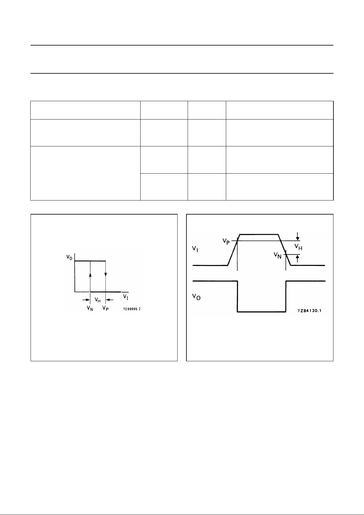
The HEF4093B consists of four Schmitt-trigger circuits.
Each circuit functions as a two-input NAND gate with
Schmitt-trigger action on both inputs. The gate switches at
different points for positive and negative-going signals.
The difference between the positive voltage (VP) and the
negative voltage (VN) is defined as hysteresis voltage
(VH).
HEF4093B
gates
Fig.2 Pinning diagram.
HEF4093BP(N): 14-lead DIL; plastic
(SOT27-1)
HEF4093BD(F): 14-lead DIL; ceramic (cerdip)
(SOT73)
HEF4093BT(D): 14-lead SO; plastic
(SOT108-1)
( ): Package Designator North America
Fig.1 Functional diagram.
January 1995 2
Fig.3 Logic diagram (one gate).
FAMILY DATA, IDDLIMITS category GATES
See Family Specifications
Page 3
Philips Semiconductors Product specification
Quadruple 2-input NAND Schmitt trigger
HEF4093B
DC CHARACTERISTICS
V
= 0 V; T
SS
Hysteresis 5 0,4 0,7 − V
voltage 10 V
Switching levels 5 1,9 2,9 3,5 V
positive-going 10 V
input voltage 15 4,7 7,3 11 V
negative-going 5 1,5 2,2 3,1 V
input voltage 10 V
amb
=25°C
V
DD
V
15 0,7 1,3 − V
15 4 6,0 10,3 V
SYMBOL MIN. TYP. MAX.
H
P
N
0,6 1,0 − V
3,6 5,2 7 V
3 4,2 6,4 V
gates
Fig.4 Transfer characteristic.
January 1995 3
Fig.5 Waveforms showing definition of
VP,VNand VH; where VNand VPare
between limits of 30% and 70%.
Page 4
Philips Semiconductors Product specification
Quadruple 2-input NAND Schmitt trigger
HEF4093B
AC CHARACTERISTICS
V
= 0 V; T
SS
Propagation delays 5 90 185 ns 63 ns + (0,55 ns/pF) C
In→ O
HIGH to LOW 15 30 60 ns 22 ns + (0,16 ns/pF) C
LOW to HIGH 10 t
Output transition times 5 60 120 ns 10 ns + (1,0 ns/pF) C
HIGH to LOW 10 t
LOW to HIGH 10 t
=25°C; CL= 50 pF; input transition times ≤ 20 ns
amb
V
DD
V
n
10 t
SYMBOL TYP. MAX.
PHL
5 85 170 ns 58 ns + (0,55 ns/pF) C
PLH
15 30 60 ns 22 ns + (0,16 ns/pF) C
THL
15 20 40 ns 6 ns + (0,28 ns/pF) C
5 60 120 ns 10 ns + (1,0 ns/pF) C
TLH
15 20 40 ns 6 ns + (0,28 ns/pF) C
TYPICAL EXTRAPOLATION
FORMULA
40 80 ns 29 ns + (0,23 ns/pF) C
40 80 ns 29 ns + (0,23 ns/pF) C
30 60 ns 9 ns + (0,42 ns/pF) C
30 60 ns 9 ns + (0,42 ns/pF) C
gates
L
L
L
L
L
L
L
L
L
L
L
L
V
DD
V
TYPICAL FORMULA FOR P (µW)
Dynamic power 5 1300 f
dissipation per 10 6400 f
package (P) 15 18 700 f
+∑(foCL) × V
i
+∑(foCL) × V
i
+∑(foCL) × V
i
DD
DD
DD
2
2
2
where
fi= input freq. (MHz)
fo= output freq. (MHz)
C
= load capacitance (pF)
L
∑ (f
) = sum of outputs
oCL
= supply voltage (V)
V
DD
January 1995 4
Page 5
Philips Semiconductors Product specification
Quadruple 2-input NAND Schmitt trigger
HEF4093B
gates
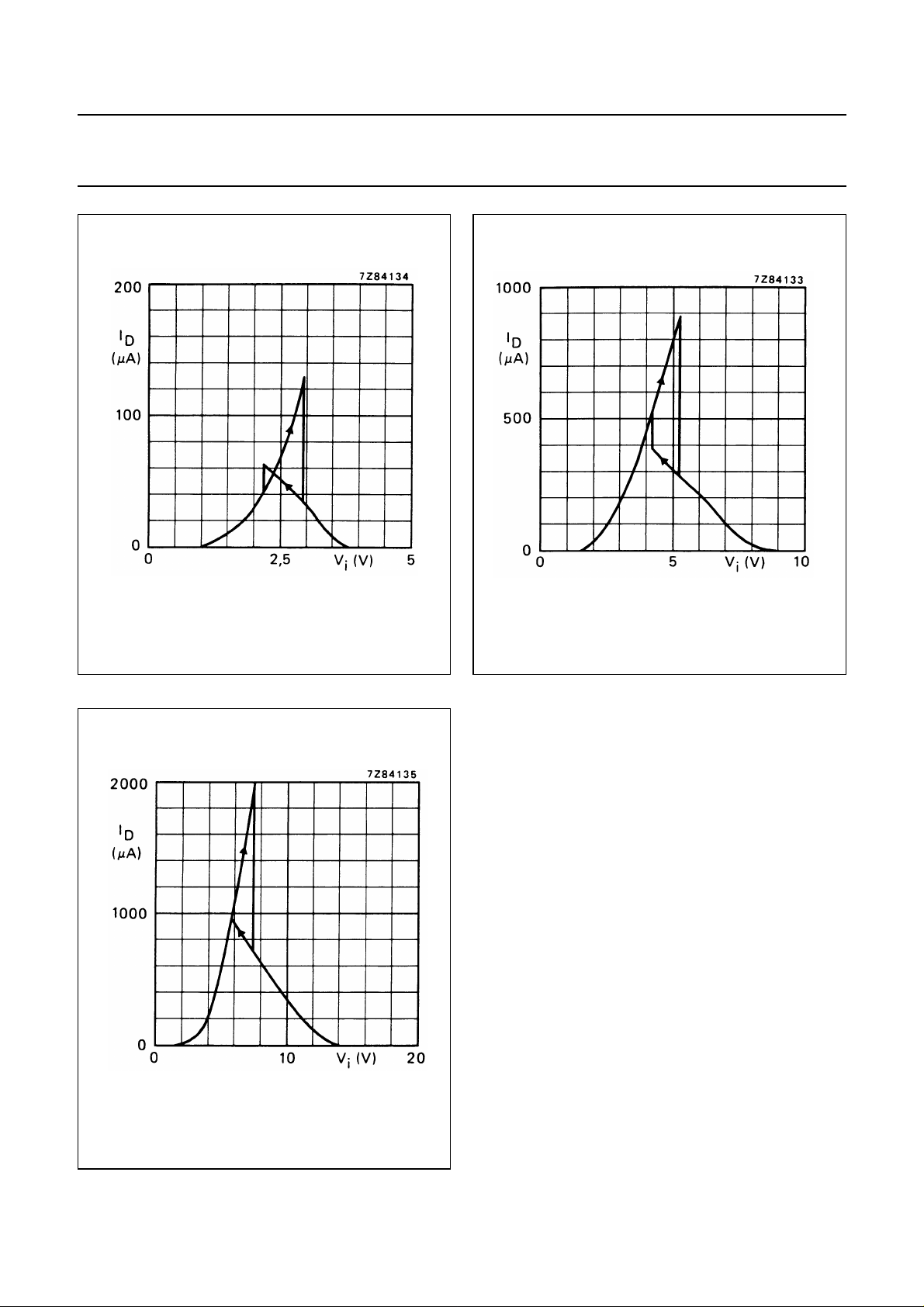
Fig.6 Typical drain current as a function of input
voltage; VDD= 5 V; T
amb
=25°C.
Fig.7 Typical drain current as a function of input
voltage; VDD=10 V; T
amb
=25°C.
Fig.8 Typical drain current as a function of input
voltage; VDD= 15 V; T
January 1995 5
amb
=25°C.
Page 6
Philips Semiconductors Product specification
Quadruple 2-input NAND Schmitt trigger
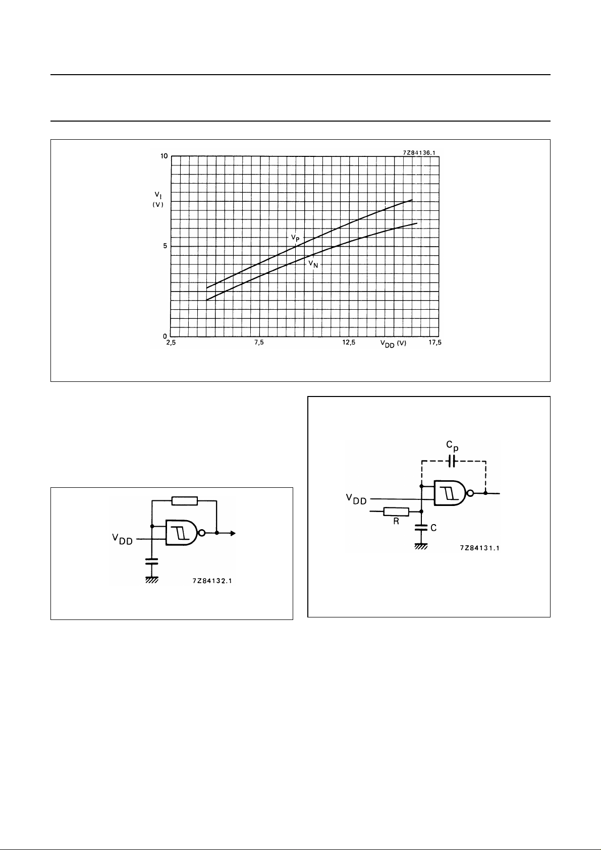
Fig.9 Typical switching levels as a function of supply voltage VDD;T
amb
HEF4093B
gates
=25°C.
APPLICATION INFORMATION
Some examples of applications for the HEF4093B are:
• Wave and pulse shapers
• Astable multivibrators
• Monostable multivibrators.
Fig.10 The HEF4093B used as a astable multivibrator.
If a Schmitt trigger is driven via a high impedance (R > 1 kΩ) then it is necessary to incorporate a capacitor C of such
value that:
V
------ -
C
C
p
–
DDVSS
---------------------------
V
H
, otherwise oscillation can occur on the edges of a pulse.>
Fig.11 Schmitt trigger driven via a high impedance
(R > 1kΩ).
C
is the external parasitic capacitance between inputs and output; the value depends on the circuit board layout.
p
Note
The two inputs may be connected together, but this will result in a larger through-current at the moment of switching.
January 1995 6
 Loading...