

Page 1

INTEGRATED CIRCUITS
DATA SH EET
For a complete data sheet, please also download:
•The IC04 LOCMOS HE4000B Logic
Family Specifications HEF, HEC
•The IC04 LOCMOS HE4000B Logic
Package Outlines/Information HEF, HEC
HEF40193B
MSI
4-bit up/down binary counter
Product specification
File under Integrated Circuits, IC04
January 1995
Page 2
Philips Semiconductors Product specification
4-bit up/down binary counter
DESCRIPTION
The HEF40193B is a 4-bit synchronous up/down
binary counter. The counter has a count-up clock input
(CPU), a count-down clock input (CPD), an asynchronous
parallel load input (PL), four parallel data inputs (P0to P3),
an asynchronous master reset input (MR), four counter
outputs (O0to O3), an active LOW terminal count-up
(carry) output (TCU) and an active LOW terminal
count-down (borrow) output (TCD).
HEF40193B
MSI
The counter outputs change state on the LOW to HIGH
transition of either clock input. However, for correct
counting, both clock inputs cannot be LOW
simultaneously. The outputs
HIGH. When the circuit has reached the maximum count
state of ‘15’, the next HIGH to LOW transition of CPUwill
cause TCUto go LOW. TCUwill stay LOW until CPU goes
HIGH again. Likewise, output TCDwill go LOW when the
circuit is in the zero state and CPDgoes LOW. When PL is
LOW, the information on P0to P3is asynchronously
loaded into the counter. A HIGH on MR resets the counter
independent of all other input conditions. The counter
stages are of a static toggle type flip-flop.
TCUand TCDare normally
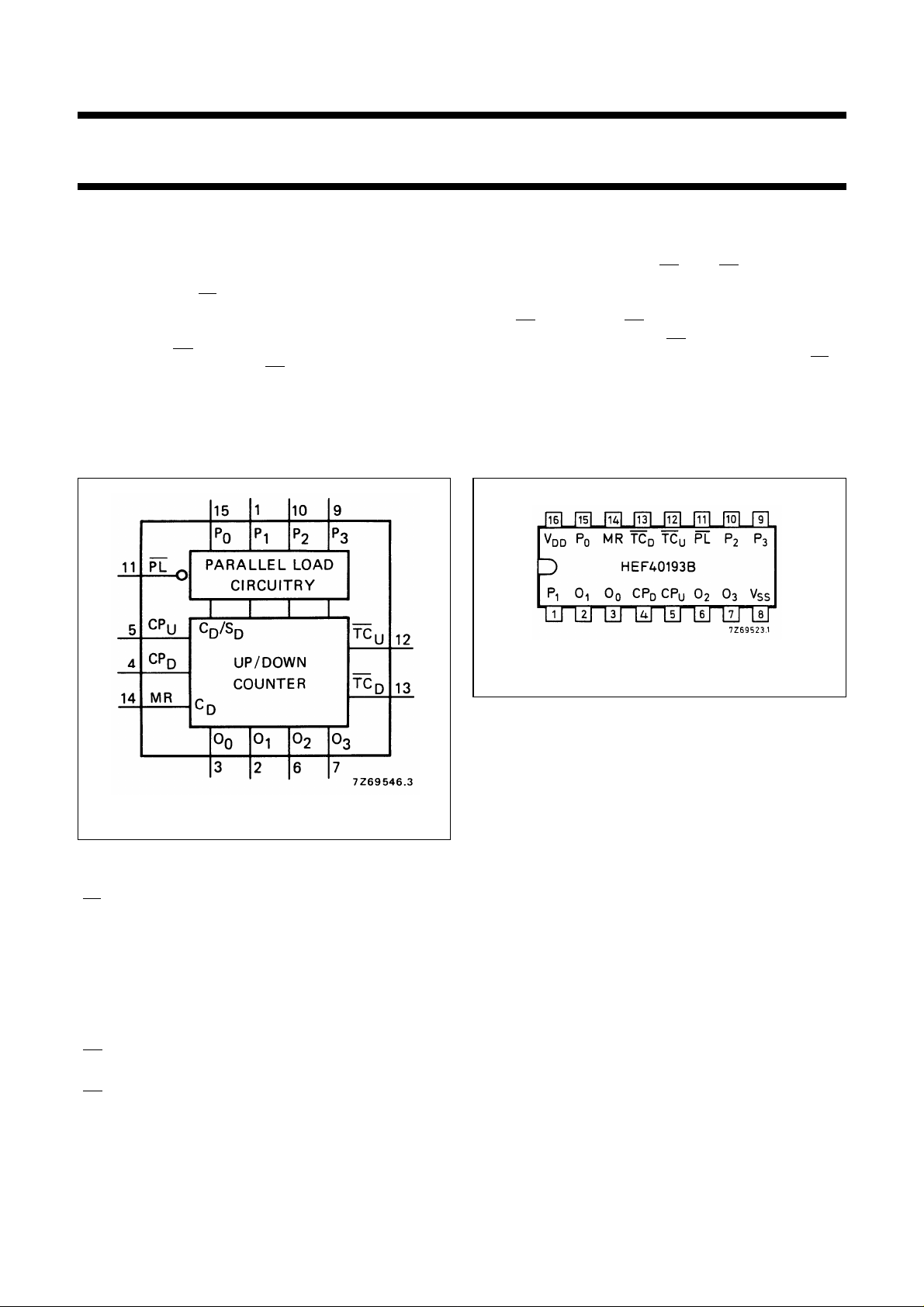
Fig.1 Functional diagram.
PINNING
PL parallel load input (active LOW)
P
CP
0
to P
U
parallel data inputs
3
count-up clock pulse input (LOW to HIGH,
edge-triggered)
CP
D
count-down clock pulse input (LOW to
HIGH, edge-triggered)
MR master reset input (asynchronous)
TC
U
buffered terminal count-up (carry) output
(active LOW)
TC
D
buffered terminal count-down
(borrow) output (active LOW)
O
to O3buffered counter outputs
0
Fig.2 Pinning diagram.
HEF40193BP(N): 16-lead DIL; plastic
(SOT38-1)
HEF40193BD(F): 16-lead DIL; ceramic (cerdip)
(SOT74)
HEF40193BT(D): 16-lead SO; plastic
(SOT109-1)
( ): Package Designator North America
FAMILY DATA, I
LIMITS category MSI
DD
See Family Specification
January 1995 2
Page 3
Philips Semiconductors Product specification
4-bit up/down binary counter
HEF40193B
MSI
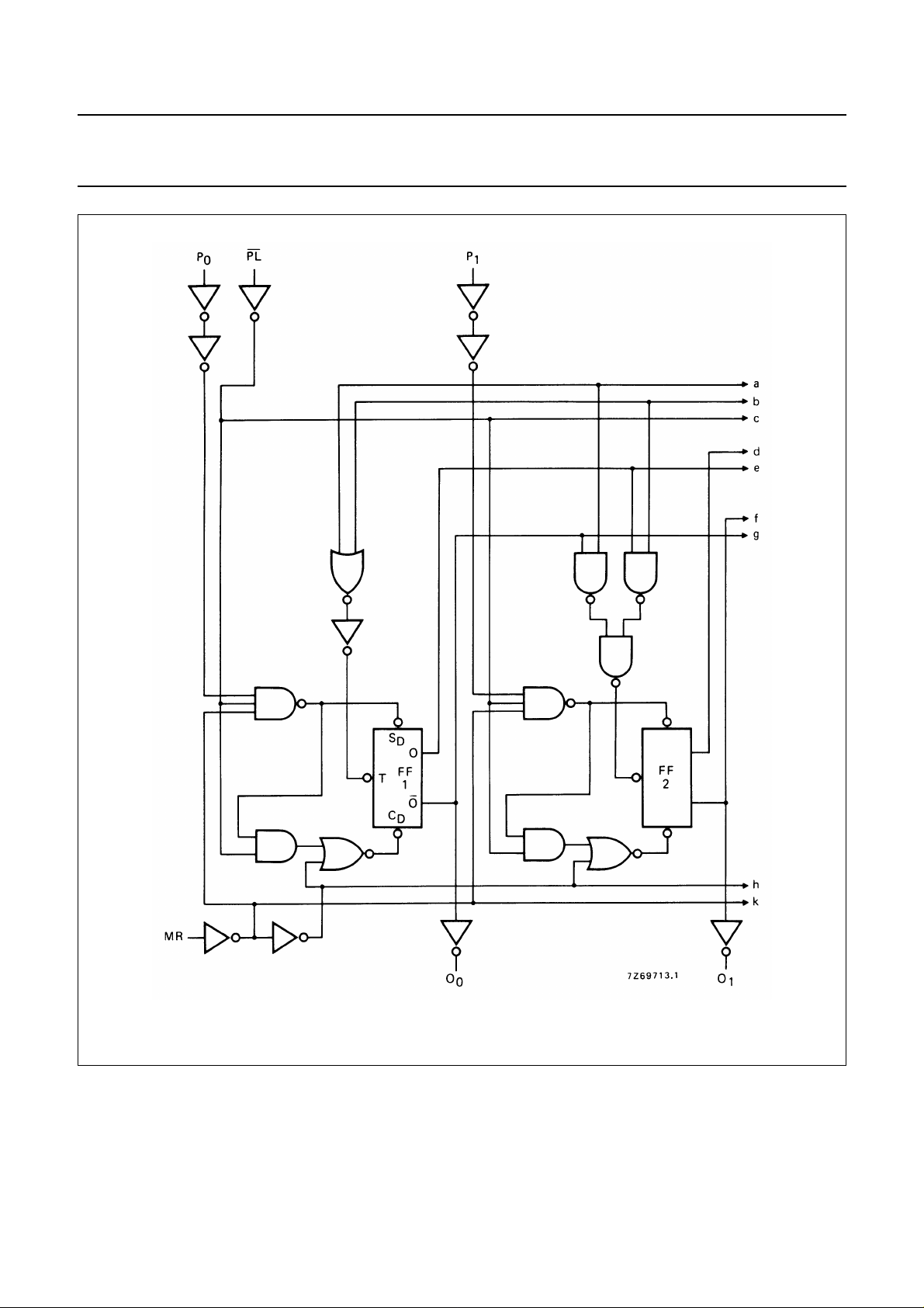
Fig.3 Logic diagram (continued on Fig.4).
January 1995 3
Page 4
Philips Semiconductors Product specification
4-bit up/down binary counter
HEF40193B
MSI
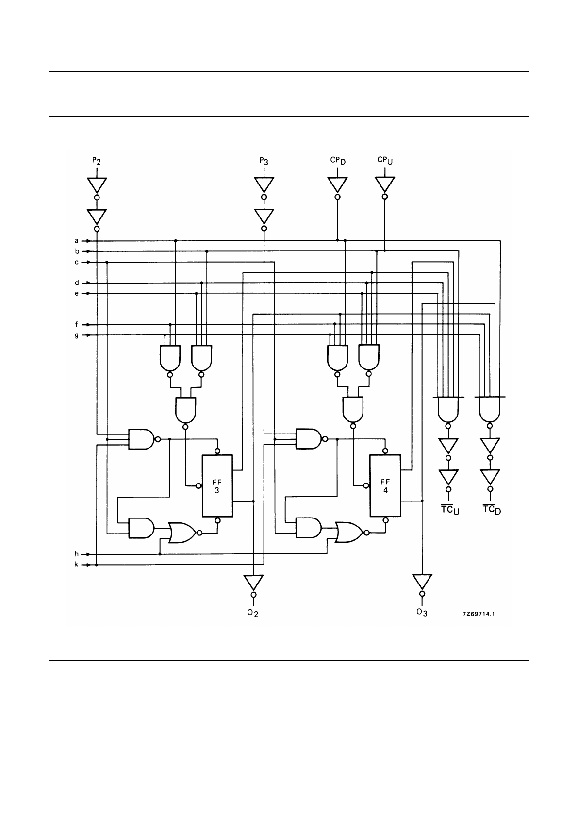
Fig.4 Logic diagram (continued from Fig.3).
January 1995 4
Page 5
Philips Semiconductors Product specification
4-bit up/down binary counter
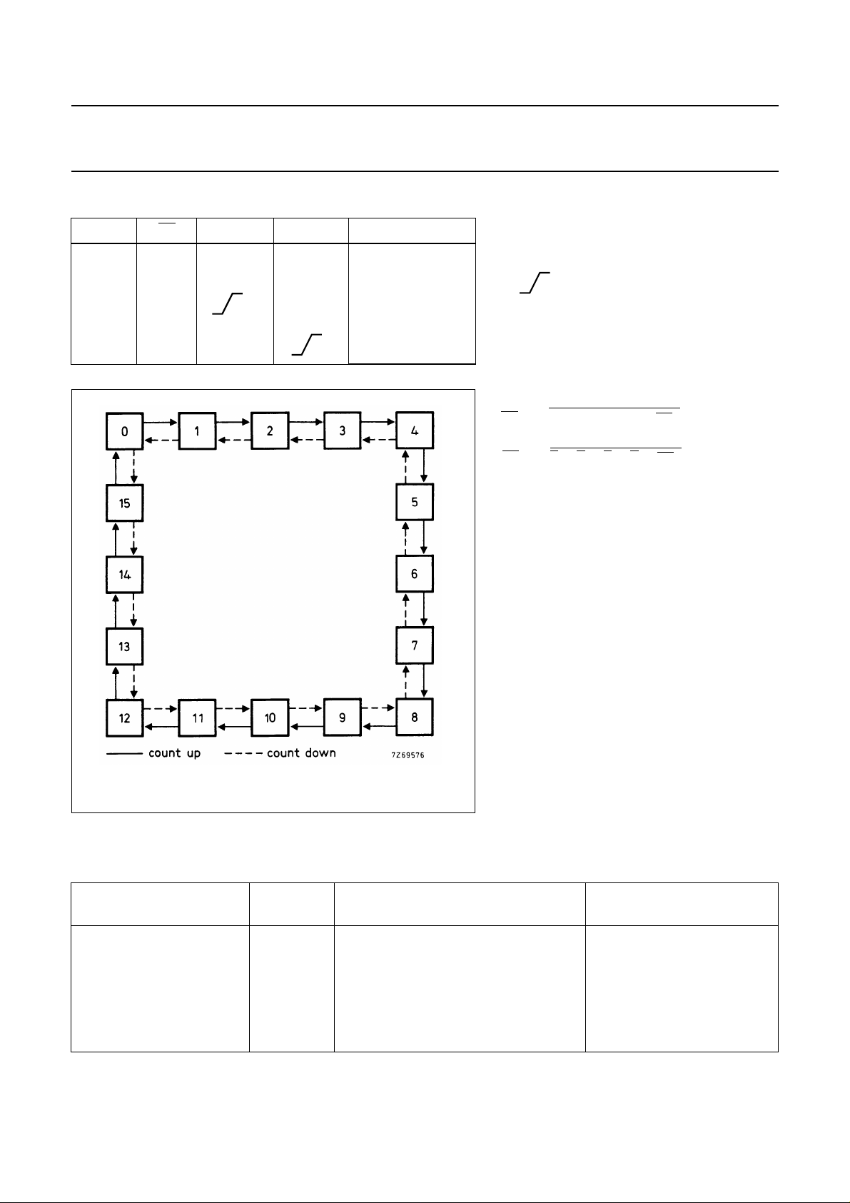
FUNCTION TABLE
MR PL CP
U
H X X X reset (asyn.)
L L X X parallel load
L H H count-up
L H H count-down
CP
D
MODE
HEF40193B
MSI
Notes
1. H = HIGH state (the more positive voltage)
L = LOW state (the less positive voltage)
X = state is immaterial
= positive-going transition
Logic equations for terminal count:
O0O1O2O3CP
TC
U
TCDO0O1O2O3CP
⋅⋅⋅⋅=
⋅⋅⋅⋅=
U
D
Fig.5 State diagram.
AC CHARACTERISTICS
V
= 0 V; T
SS
=25°C; input transition times ≤ 20 ns
amb
V
DD
V
TYPICAL FORMULA FOR P (µW)
Dynamic power 5 600 f
dissipation per 10 2700 f
package (P) 15 7500 f
January 1995 5
+∑(foCL) × V
i
+∑(foCL) × V
i
+∑(foCL) × V
i
DD
DD
DD
2
2
2
where
fi= input freq. (MHz)
fo= output freq. (MHz)
C
= load capacitance (pF)
L
) = sum of outputs
∑ (f
oCL
V
= supply voltage (V)
DD
Page 6
Philips Semiconductors Product specification
4-bit up/down binary counter
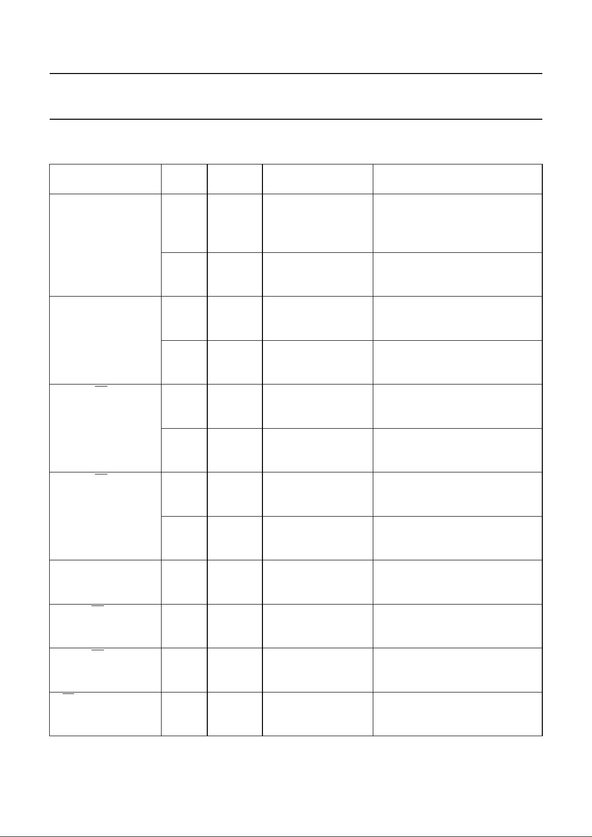
AC CHARACTERISTICS
V
= 0 V; T
SS
Propagation delays
CPU→ O
HIGH to LOW 10 t
LOW to HIGH 10 t
CPD→ O
HIGH to LOW 10 t
LOW to HIGH 10 t
CPU→ TC
HIGH to LOW 10 t
LOW to HIGH 10 t
CPD→ TC
HIGH to LOW 10 t
LOW to HIGH 10 t
MR → O
HIGH to LOW 10 t
MR → TC
LOW to HIGH 10 t
MR → TC
HIGH to LOW 10 t
PL → O
HIGH to LOW 10 t
=25°C; CL= 50 pF; input transition times ≤ 20 ns
amb
V
DD
V
n
5 210 415 ns 183 ns + (0,55 ns/pF) C
15 60 120 ns 52 ns + (0,16 ns/pF) C
5 170 340 ns 143 ns + (0,55 ns/pF) C
15 50 100 ns 42 ns + (0,16 ns/pF) C
n
5 210 425 ns 183 ns + (0,55 ns/pF) C
15 60 125 ns 57 ns + (0,16 ns/pF) C
5 170 340 ns 143 ns + (0,55 ns/pF) C
15 50 100 ns 42 ns + (0,16 ns/pF) C
U
5 125 250 ns 98 ns + (0,55 ns/pF) C
15 35 70 ns 27 ns + (0,16 ns/pF) C
5 95 185 ns 68 ns + (0,55 ns/pF) C
15 30 60 ns 22 ns + (0,16 ns/pF) C
D
5 140 280 ns 113 ns + (0,55 ns/pF) C
15 40 80 ns 32 ns + (0,16 ns/pF) C
5 100 195 ns 73 ns + (0,55 ns/pF) C
15 30 65 ns 22 ns + (0,16 ns/pF) C
n
5 195 390 ns 168 ns + (0,55 ns/pF) C
15 60 120 ns 52 ns + (0,16 ns/pF) C
U
5 145 285 ns 118 ns + (0,55 ns/pF) C
15 45 90 ns 37 ns + (0,16 ns/pF) C
D
5 365 730 ns 338 ns + (0,55 ns/pF) C
15 100 205 ns 92 ns + (0,16 ns/pF) C
n
5 185 360 ns 158 ns + (0,55 ns/pF) C
15 55 110 ns 47 ns + (0,16 ns/pF) C
SYMBOL MIN. TYP. MAX.
PHL
PLH
PHL
PLH
PHL
PLH
PHL
PLH
PHL
PLH
PHL
PHL
85 165 ns 74 ns + (0,23 ns/pF) C
70 140 ns 59 ns + (0,23 ns/pF) C
85 170 ns 74 ns + (0,23 ns/pF) C
70 140 ns 59 ns + (0,23 ns/pF) C
50 100 ns 39 ns + (0,23 ns/pF) C
40 80 ns 29 ns + (0,23 ns/pF) C
55 110 ns 44 ns + (0,23 ns/pF) C
40 85 ns 29 ns + (0,23 ns/pF) C
80 160 ns 69 ns + (0,23 ns/pF) C
60 115 ns 49 ns + (0,23 ns/pF) C
130 265 ns 119 ns + (0,23 ns/pF) C
75 150 ns 64 ns + (0,23 ns/pF) C
HEF40193B
MSI
TYPICAL EXTRAPOLATION
FORMULA
L
L
L
L
L
L
L
L
L
L
L
L
L
L
L
L
L
L
L
L
L
L
L
L
L
L
L
L
L
L
L
L
L
L
L
L
January 1995 6
Page 7
Philips Semiconductors Product specification
4-bit up/down binary counter
HEF40193B
V
DD
V
SYMBOL MIN. TYP. MAX.
5 145 290 ns 118 ns + (0,55 ns/pF) C
LOW to HIGH 10 t
PLH
60 120 ns 49 ns + (0,23 ns/pF) C
15 45 90 ns 37 ns + (0,16 ns/pF) C
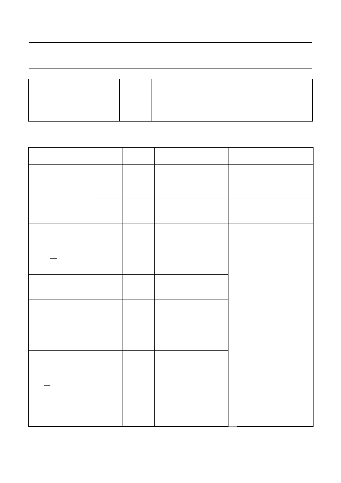
AC CHARACTERISTICS
V
= 0 V; T
SS
=25°C; CL= 50 pF; input transition times ≤ 20 ns
amb
V
DD
V
SYMBOL MIN. TYP. MAX.
Output transition
times 5 60 120 ns 10 ns + (1,0 ns/pF) C
HIGH to LOW 10 t
THL
30 60 ns 9 ns + (0,42 ns/pF) C
15 20 40 ns 6 ns + (0,28 ns/pF) C
5 60 120 ns 10 ns + (1,0 ns/pF) C
LOW to HIGH 10 t
TLH
30 60 ns 9 ns + (0,42 ns/pF) C
15 20 40 ns 6 ns + (0,28 ns/pF) C
Set-up time 5 160 80 ns
→ PL 10 t
P
n
su
60 30 ns
15 50 25 ns
Hold time 5 10 −70 ns
P
→ PL 10 t
n
hold
5 −25 ns
15 5 −20 ns
Minimum CPUor CP
D
pulse width; LOW 10 t
5 150 75 ns
WCPL
50 25 ns
15 35 20 ns
Minimum MR 5 180 90 ns
pulse width; HIGH 10 t
WMRH
70 35 ns
15 60 30 ns
Minimum
pulse width; LOW 10 t
PL 5 120 60 ns
WPLL
45 20 ns
15 30 15 ns
Recovery time 5 125 65 ns
for MR 10 t
RMR
70 35 ns
15 50 25 ns
Recovery time 5 90 45 ns
for
PL 10 t
RPL
35 15 ns
15 25 10 ns
Maximum clock 5 2,5 5 MHz
pulse frequency 10 f
max
7 14 MHz
15 9 18 MHz
TYPICAL EXTRAPOLATION
FORMULA
L
L
L
TYPICAL EXTRAPOLA TION
FORMULA
see also waveforms
Fig.6
MSI
L
L
L
L
L
L
January 1995 7
Page 8
Philips Semiconductors Product specification
4-bit up/down binary counter
HEF40193B
MSI
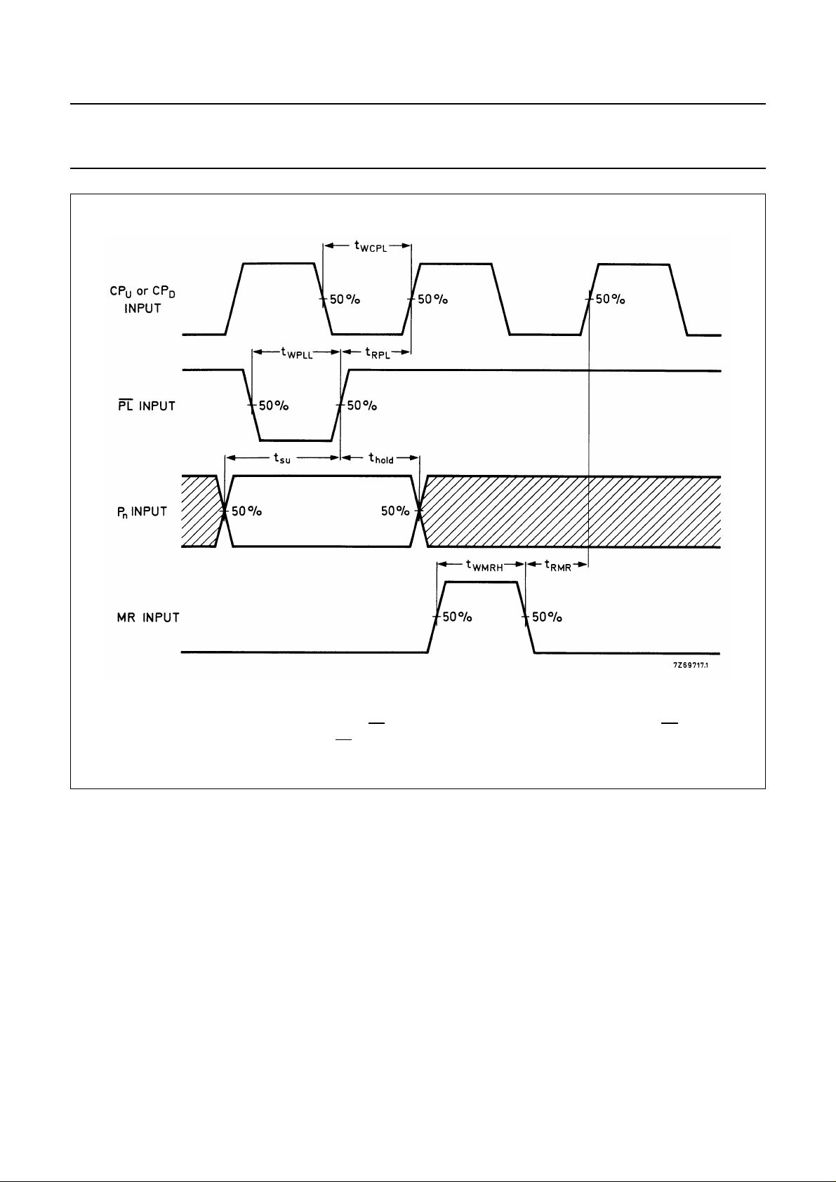
Fig.6 Waveforms showing recovery times for PL and MR, minimum pulse widths for CPU,CPD,PL and MR,
and set-up and hold times for P to PL. Set-up times and hold times are shown as positive values but may
be specified as negative values.
January 1995 8
Page 9
Philips Semiconductors Product specification
4-bit up/down binary counter
HEF40193B
MSI
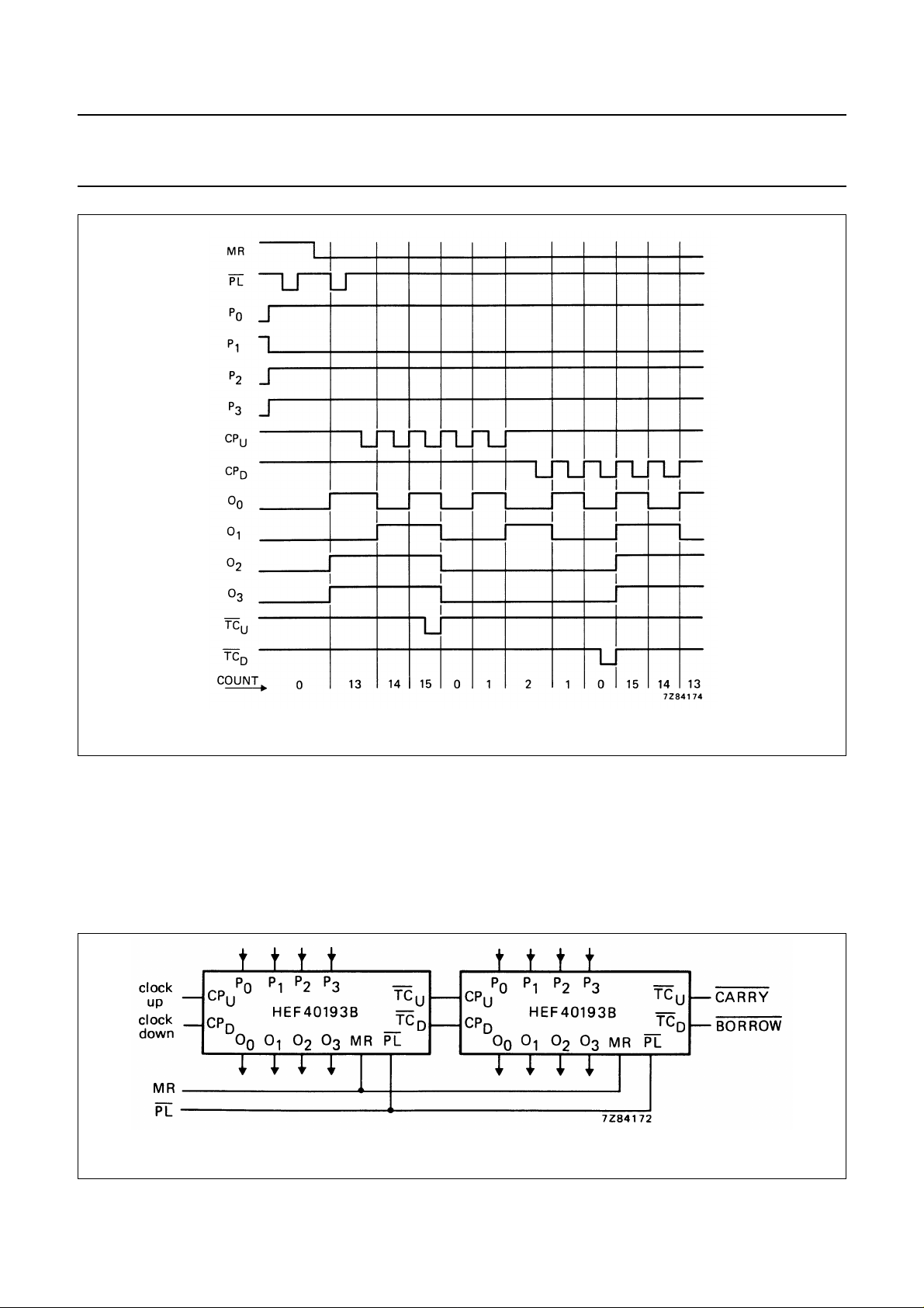
Fig.7 Timing diagram.
APPLICATION INFORMATION
Some examples of applications for the HEF40193B are:
• Up/down difference counting
• Multistage ripple counting
• Multistage synchronous counting
Fig.8 Example of cascaded HEF40193B ICs.
January 1995 9
 Loading...