

Page 1

INTEGRATED CIRCUITS
DATA SH EET
For a complete data sheet, please also download:
•The IC04 LOCMOS HE4000B Logic
Family Specifications HEF, HEC
•The IC04 LOCMOS HE4000B Logic
Package Outlines/Information HEF, HEC
HEF4015B
MSI
Dual 4-bit static shift register
Product specification
File under Integrated Circuits, IC04
January 1995
Page 2
Philips Semiconductors Product specification
Dual 4-bit static shift register
DESCRIPTION
The HEF4015B is a dual edge-triggered 4-bit static shift
register (serial-to-parallel converter). Each shift register
has a serial data input (D), a clock input (CP), four fully
buffered parallel outputs (O0to O3) and an overriding
asynchronous master reset input (MR). Information
HEF4015B
MSI
present on D is shifted to the first register position, and all
the data in the register is shifted one position to the right
on the LOW-to-HIGH transition of CP. A HIGH on MR
clears the register and forces O
independent of CP and D. Schmitt-trigger action in the
clock input makes the circuit highly tolerant to slower clock
rise and fall times.
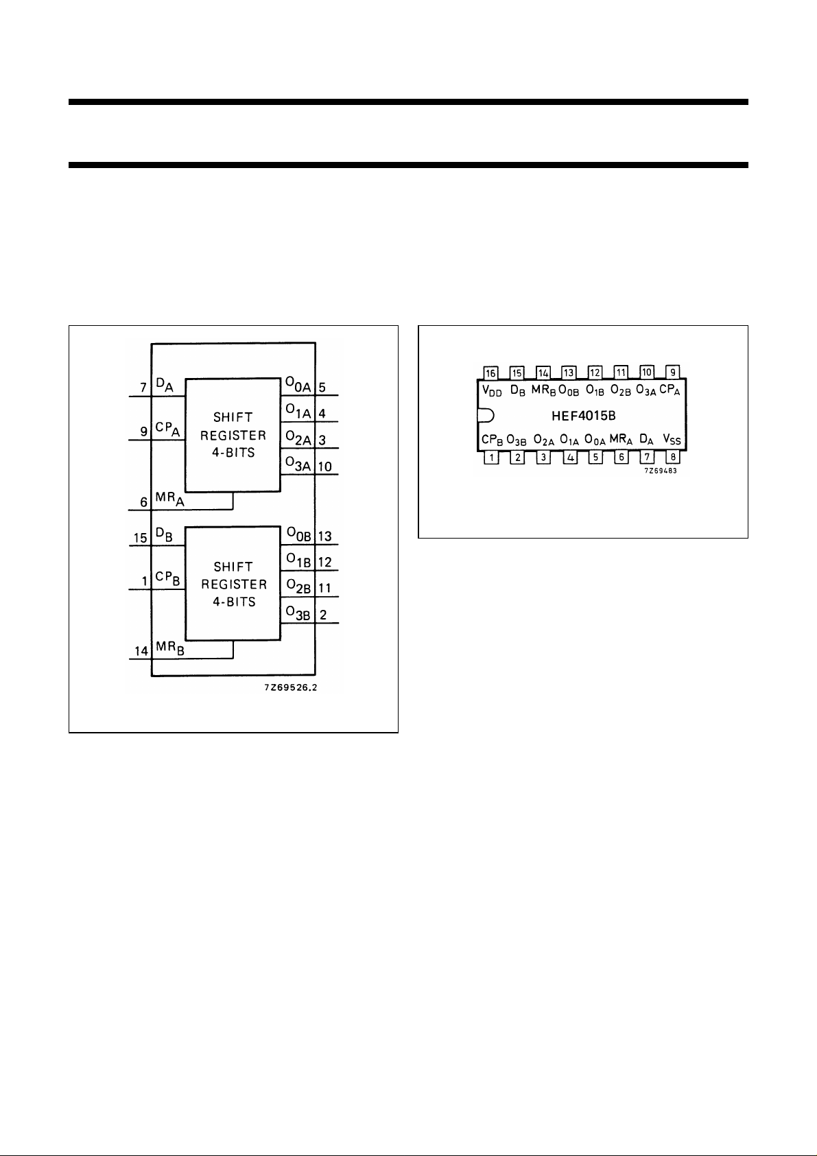
Fig.2 Pinning diagram.
to O3to LOW,
0
Fig.1 Functional diagram.
PINNING
D
MR
CP
, D
A
B
, MR
A
B
, CP
A
B
serial data input
master reset input (active HIGH)
clock input (LOW-to-HIGH
edge-triggered)
O
, O1A, O2A, O
0A
O
, O1B, O2B, O
0B
parallel outputs
3A
parallel outputs
3B
APPLICATION INFORMATION
Some examples of applications for the HEF4015B are:
• Serial-to-parallel converter
• Buffer stores
• General purpose register
HEF4015BP(N): 16-lead DIL; plastic
(SOT38-1)
HEF4015BD(F): 16-lead DIL; ceramic (cerdip)
(SOT74)
HEF4015BT(D): 16-lead SO; plastic
(SOT109-1)
( ): Package Designator North America
FAMILY DATA, I
LIMITS category MSI
DD
See Family Specifications
January 1995 2
Page 3
Philips Semiconductors Product specification
Dual 4-bit static shift register
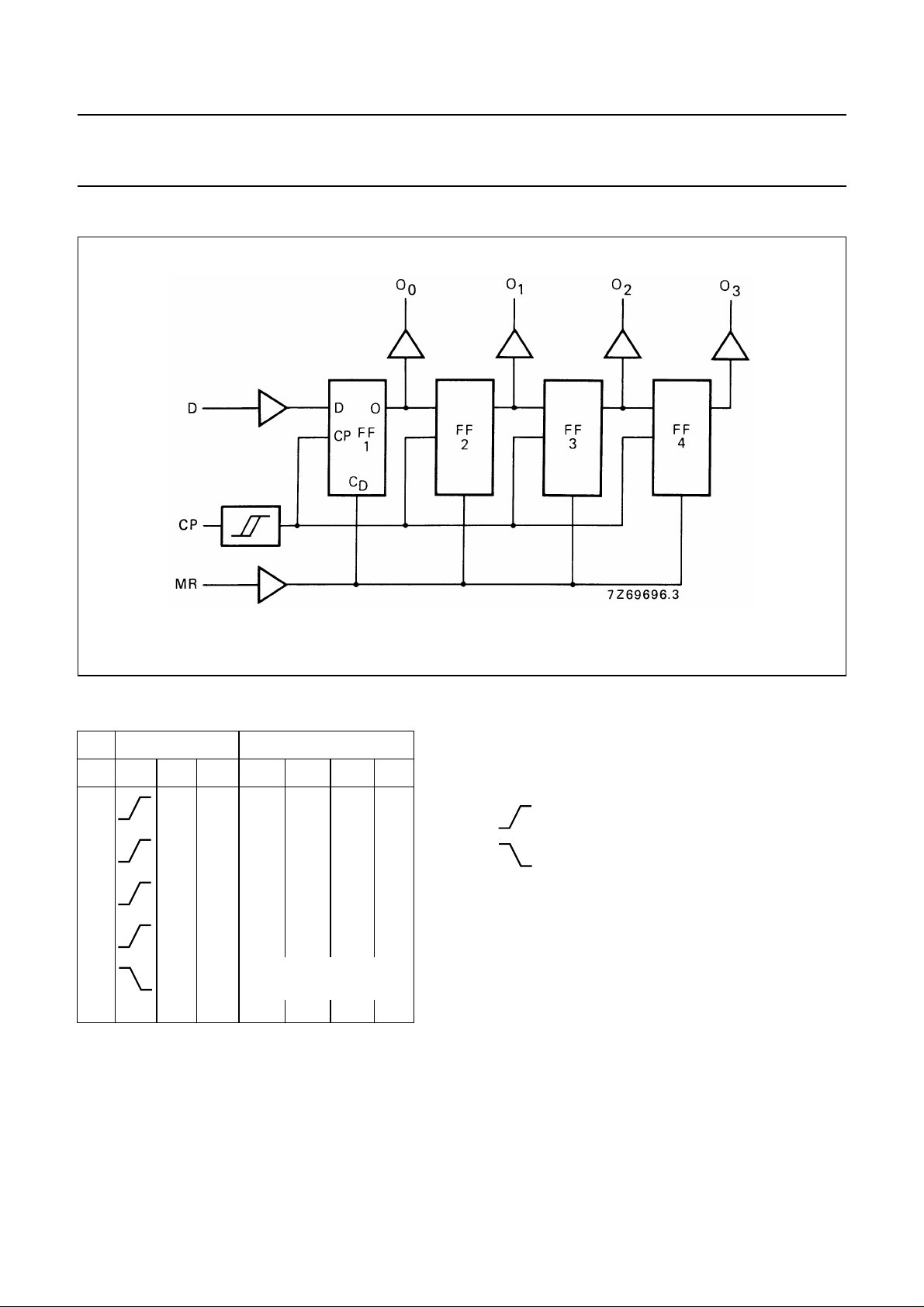
LOGIC DIAGRAM (one register)
HEF4015B
MSI
FUNCTION TABLE
INPUTS OUTPUTS
n CP D MR O
1D
2D
3D
4D
LD1XXX
1
LD2D1XX
2
LD3D2D1X
3
LD4D3D2D
4
X L no change
XXH L L LL
Fig.3 Logic diagram.
Note
1. H = HIGH state (the more positive voltage)
O
1
O2O
3
0
2. L = LOW state (the less positive voltage)
3. X = state is immaterial
4. = positive-going transition
5. = negative-going transition
6. D
= either HIGH or LOW
n
7. n = number of clock pulse transitions
1
January 1995 3
Page 4
Philips Semiconductors Product specification
Dual 4-bit static shift register
HEF4015B
MSI
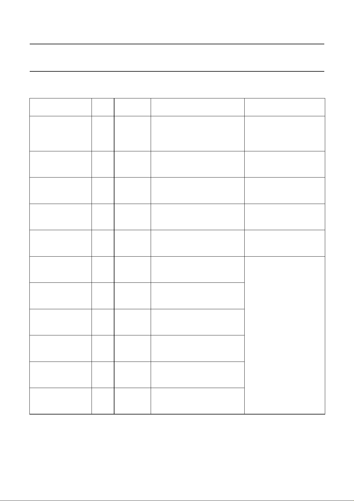
AC CHARACTERISTICS
V
= 0 V; T
SS
Propagation delays
CP → O
HIGH to LOW 10 t
LOW to HIGH 10 t
MR → O
HIGH to LOW 10 t
Output transition times 5 60 120 ns 10 ns + (1,0 ns/pF) C
HIGH to LOW 10 t
LOW to HIGH 10 t
Set-up time 5 25 −15 ns
D → CP 10 t
Hold time 5 40 20 ns
D → CP 10 t
Minimum clock 5 60 30 ns
pulse width; LOW 10 t
Minimum MR 5 80 40 ns
pulse width; HIGH 10 t
Recovery time 5 50 20 ns
for MR 10 t
Maximum clock 5 7 15 MHz
pulse frequency 10 f
=25°C; CL= 50 pF; input transition times ≤20 ns
amb
V
DD
V
n
5 130 260 ns 103 ns + (0,55 ns/pF) C
SYMBOL MIN. TYP. MAX.
PHL
15 40 80 ns 32 ns + (0,16 ns/pF) C
5 120 240 ns 93 ns + (0,55 ns/pF) C
PLH
15 40 80 ns 32 ns + (0,16 ns/pF) C
n
5 105 210 ns 78 ns + (0,55 ns/pF) C
PHL
15 35 70 ns 27 ns + (0,16 ns/pF) C
THL
15 20 40 ns 6 ns + (0,28 ns/pF) C
5 60 120 ns 10 ns + (1,0 ns/pF) C
TLH
15 20 40 ns 6 ns + (0,28 ns/pF) C
su
25 −10 ns
15 20 −5ns
hold
20 10 ns
15 15 8 ns
WCPL
30 15 ns
15 20 10 ns
WMRH
30 15 ns
15 24 12 ns
RMR
30 10 ns
15 20 5 ns
max
15 30 MHz
15 22 44 MHz
TYPICAL EXTRAPOLATION
FORMULA
55 110 ns 44 ns + (0,23 ns/pF) C
55 110 ns 44 ns + (0,23 ns/pF) C
45 90 ns 34 ns + (0,23 ns/pF) C
30 60 ns 9 ns + (0,42 ns/pF) C
30 60 ns 9 ns + (0,42 ns/pF) C
see waveforms Figs 4 and 5
L
L
L
L
L
L
L
L
L
L
L
L
L
L
L
January 1995 4
Page 5
Philips Semiconductors Product specification
Dual 4-bit static shift register
V
DD
V
Dynamic power 5 1 500 f
dissipation per 10 6 300 f
package (P) 15 17 000 f
TYPICAL FORMULA FOR P (µW)
+∑(foCL) × V
i
+∑(foCL) × V
i
+∑(foCL) × V
i
DD
DD
DD
HEF4015B
MSI
2
2
2
where
fi= input freq. (MHz)
fo= output freq. (MHz)
C
= load capacitance (pF)
L
∑ (f
V
) = sum of outputs
oCL
= supply voltage (V)
DD
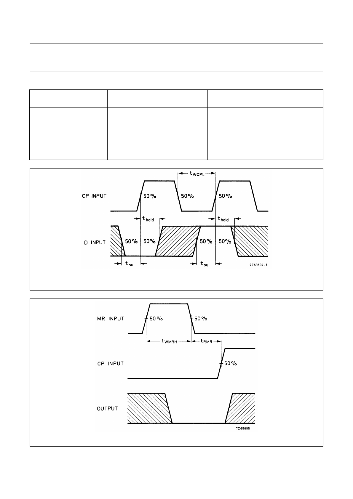
Fig.4 Waveforms showing set-up times, hold times and minimum clock pulse width. Set-up and hold times are
shown as positive values but may be specified as negative values.
Fig.5 Waveforms showing recovery time for MR and minimum MR pulse width.
January 1995 5
 Loading...