

Page 1
DATA SH EET
Product specification
File under Integrated Circuits, IC04
January 1995
INTEGRATED CIRCUITS
HEF4011UB
gates
Quadruple 2-input NAND gate
For a complete data sheet, please also download:
•The IC04 LOCMOS HE4000B Logic
Family Specifications HEF, HEC
•The IC04 LOCMOS HE4000B Logic
Package Outlines/Information HEF, HEC
Page 2
January 1995 2
Philips Semiconductors Product specification
Quadruple 2-input NAND gate
HEF4011UB
gates
DESCRIPTION
The HEF4011UB is a quadruple 2-input NAND gate. This
unbuffered single stage version provides a direct
implementation of the NAND function. The output
impedance and output transition time depends on the input
voltage and input rise and fall times applied.
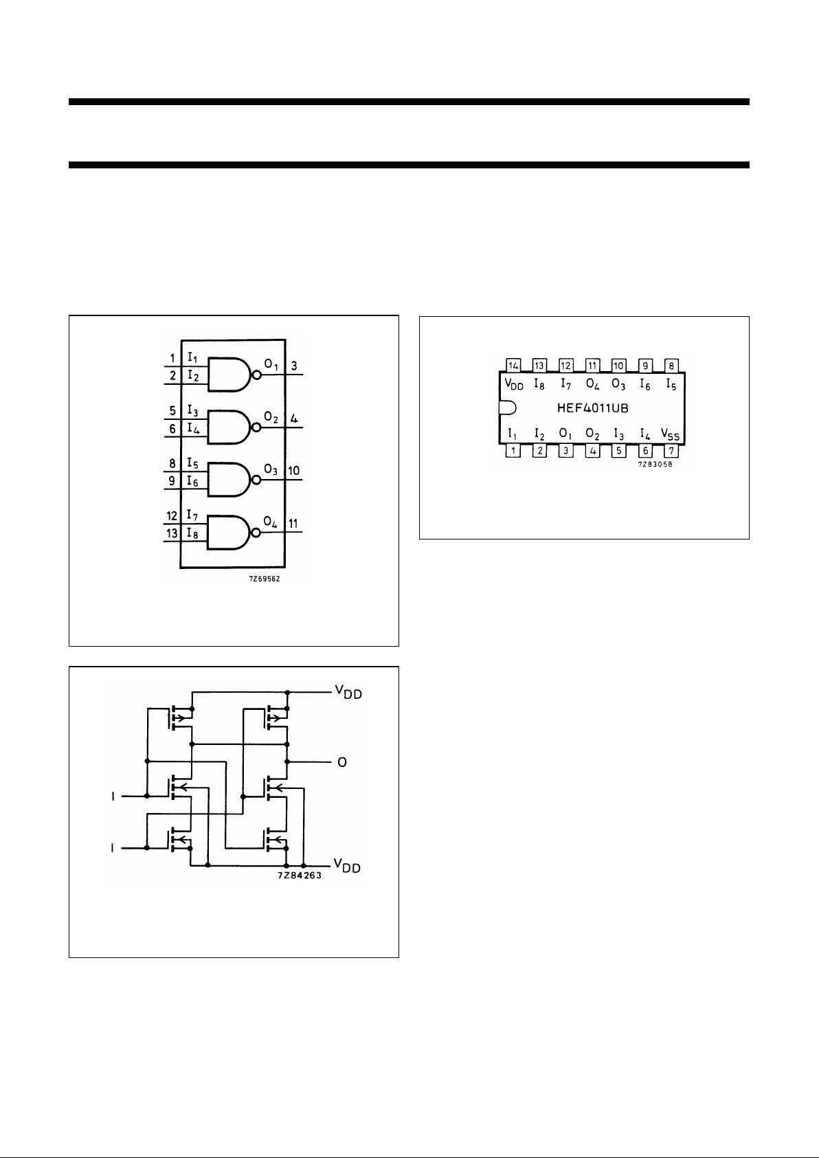
Fig.1 Functional diagram.
HEF4011UBP(N): 14-lead DIL; plastic
(SOT27-1)
HEF4011UBD(F): 14-lead DIL; ceramic (cerdip)
(SOT73)
HEF4011UBT(D): 14-lead SO; plastic
(SOT108-1)
( ): Package Designator North America
Fig.2 Pinning diagram.
FAMILY DATA, IDDLIMITS category GATES
See Family Specifications for V
IH/VIL
unbuffered stages
Fig.3 Schematic diagram (one gate). The
splitting-up of the n-transistors provide
identical inputs.
Page 3

January 1995 3
Philips Semiconductors Product specification
Quadruple 2-input NAND gate
HEF4011UB
gates
AC CHARACTERISTICS
V
SS
= 0 V; T
amb
=25°C; CL= 50 pF; input transition times ≤20 ns
V
DD
V
SYMBOL TYP. MAX.
TYPICAL EXTRAPOLATION
FORMULA
Propagation delays
In→ O
n
5 60 120 ns 25 ns + (0,70 ns/pF) C
L
HIGH to LOW 10 t
PHL
25 50 ns 12 ns + (0,27 ns/pF) C
L
15 20 40 ns 10 ns + (0,20 ns/pF) C
L
5 35 70 ns 8 ns + (0,55 ns/pF) C
L
LOW to HIGH 10 t
PLH
20 40 ns 9 ns + (0,23 ns/pF) C
L
15 17 35 ns 9 ns + (0,16 ns/pF) C
L
Output transition 5 75 150 ns 15 ns + (1,20 ns/pF) C
L
times 10 t
THL
30 60 ns 6 ns + (0,48 ns/pF) C
L
HIGH to LOW 15 20 40 ns 4 ns + (0,32 ns/pF) C
L
5 60 110 ns 10 ns + (1,00 ns/pF) C
L
LOW to HIGH 10 t
TLH
30 60 ns 9 ns + (0,42 ns/pF) C
L
15 20 40 ns 6 ns + (0,28 ns/pF) C
L
Input capacitance C
IN
10 pF
V
DD
V
TYPICAL FORMULA FOR P (µW)
Dynamic power 5 500 f
i
+∑(foCL) × V
DD
2
where
dissipation per 10 5 000 f
i
+∑(foCL) × V
DD
2
fi= input freq. (MHz)
package (P) 15 25 000 f
i
+∑(foCL) × V
DD
2
fo= output freq. (MHz)
C
L
= load capacitance (pF)
∑ (f
oCL
) = sum of outputs
V
DD
= supply voltage (V)
Page 4
January 1995 4
Philips Semiconductors Product specification
Quadruple 2-input NAND gate
HEF4011UB
gates
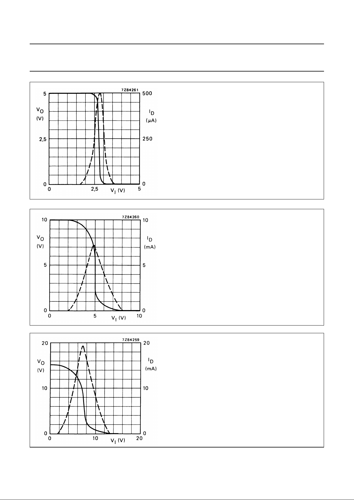
Fig.4 Typical transfer characteristics; one input, the other
input connected to VDD;
VO;
−−−ID(drain current);
IO= 0; VDD=5V.
Fig.5 Typical transfer characteristics; one input, the other
input connected to VDD;
VO;
−−−ID(drain current);
IO= 0; VDD= 10 V.
Fig.6 Typical transfer characteristics; one input, the other
input connected to VDD;
VO;
−−−ID(drain current);
IO= 0; VDD= 15 V.
Page 5
January 1995 5
Philips Semiconductors Product specification
Quadruple 2-input NAND gate
HEF4011UB
gates
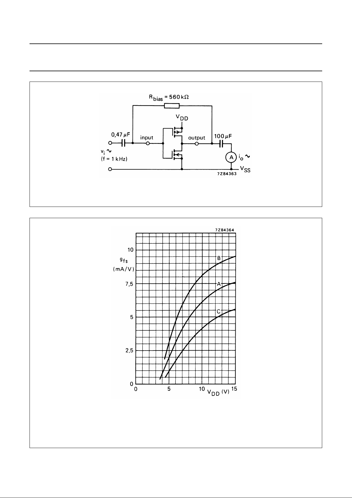
Fig.7 Test set-up for measuring forward transconductance gfs=dio/dviat vois constant (see also graph Fig.8).
Fig.8 Typical forward transconductance gfsas a function of the supply voltage at T
amb
=25°C.
A : average,
B : average + 2 s,
C : average − 2 s, where ‘s’ is the observed standard deviation.
Page 6
January 1995 6
Philips Semiconductors Product specification
Quadruple 2-input NAND gate
HEF4011UB
gates
APPLICATION INFORMATION
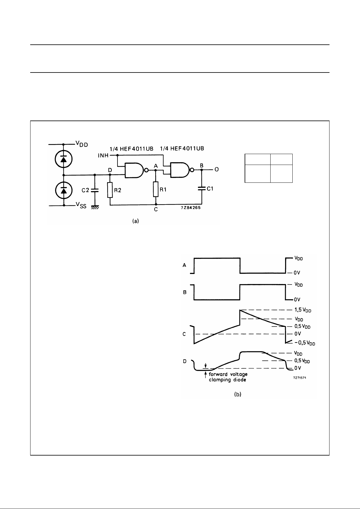
Some examples of applications for the HEF4011UB are shown below.
Because of the fact that this circuit is unbuffered, it is suitable for use in (partly) analogue circuits.
Fig.9 (a) Astable relaxation oscillator using two HEF4011UB gates; the diodes may be BAW62; C2 is a parasitic
capacitance.
(b) Waveforms at the points marked A, B, C and D in the circuit diagram.
INH O
LH
H OSC
In Fig.9 the oscillation frequency is mainly determined by R1C1,
provided R1 << R2 and R2C2 << R1C1.
The function of R2 is to minimize the influence of the forward voltage
across the protection diodes on the frequency; C2 is a stray (parasitic)
capacitance. The period T
p
is given by Tp= T1+ T2, in which
V
ST
is the signal threshold level of the gate. The period is fairly
independent of V
DD
, VSTand temperature. The duty factor, however, is
influenced by V
ST
.
T
1
R1C1 In
V
DDVST
+
V
ST
---------------------------
and T
2
R1C1 In
2V
DDVST
–
V
DDVST
–
------------------------------ -
where==
Page 7
January 1995 7
Philips Semiconductors Product specification
Quadruple 2-input NAND gate
HEF4011UB
gates
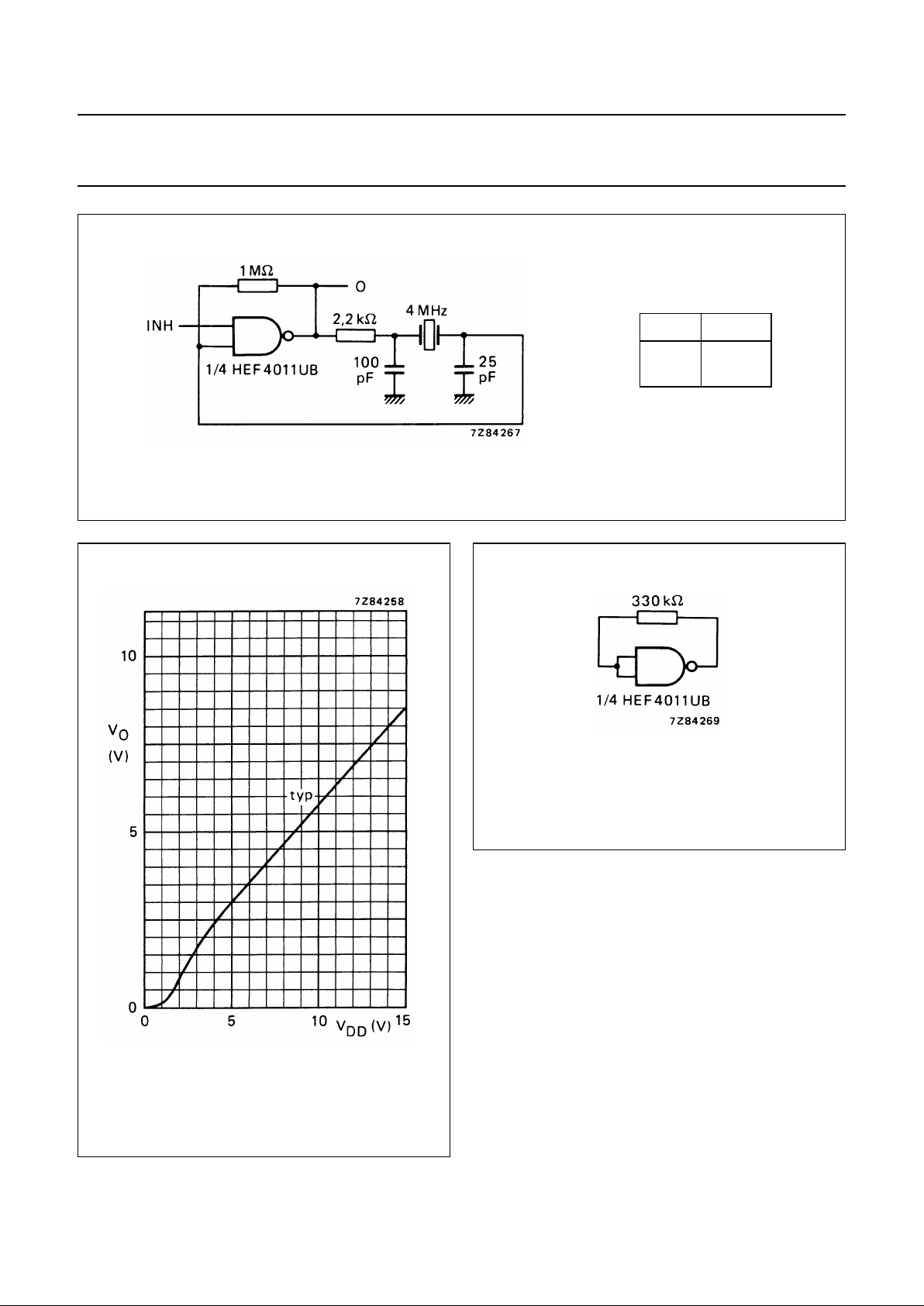
Fig.10 Example of a crystal oscillator using one HEF4011UB gate.
INH O
LH
H OSC
Fig.11 Output voltage as a function of supply
voltage.
NOTES
If a gate is just used as an amplifying inverter, there are
two possibilities:
• Connecting the inputs together gives simpler wiring, but
makes the device output not completely symmetrical.
• Connecting one input to VDDwill give the device a
symmetrical output.
Fig.12 Test set-up for measuring graph of Fig.11.
Condition: all other inputs connected to
ground.
Page 8
January 1995 8
Philips Semiconductors Product specification
Quadruple 2-input NAND gate
HEF4011UB
gates
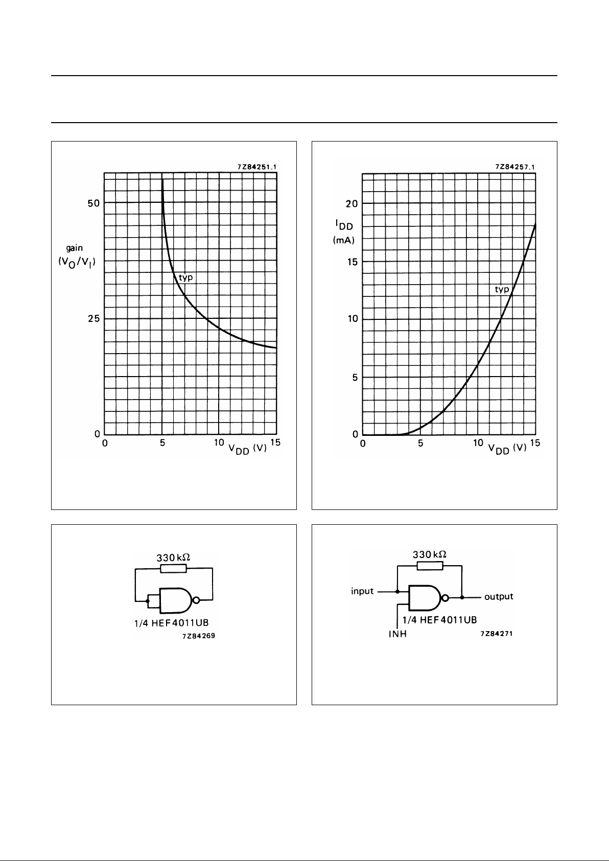
Fig.13 Voltage gain (VO/VI) as a function of supply
voltage.
Fig.14 Supply current as a function of supply
voltage.
Fig.15 Test set-up for measuring graphs of Figs 13
and 14. Condition: all other inputs
connected to ground.
Fig.16 Example of an analogue amplifier with
inhibit using one HEF4011UB gate.
 Loading...