

Page 1

HA AND HD SERIES | 48
PANEL MOUNT
PRODUCT SELECTION
Control Voltage 12A
4-32 VDC HD4812
90-280 Vrms HA4812
18-36 Vrms HA4812E
25A
HD4825
HA4825
HA4825E
Features
• Ratings from 12A to 125A @ 48-530 VAC
• SCR output for heavy industrial loads
• Zero Voltage or instantaneous turn-on outputs
• UL/CSA/TUV Approved, CE Compliant to EN60950-1
• Improved SEMS screw and washer
• Redesigned housing with anti-rotation barriers
• AC or DC control
• Direct bond copper substrate
• Direct power lead frame
• Epoxy free design
50A
HD4850
HA4850
HA4850E
75A
HD4875
HA4875
HA4875E
90A
HD4890
HA4890
HA4890E
110A
HD48110
HA48110
HA48110E
125A
HD48125
HA48125
HA48125E
ORDERING OPTIONS
H A 48 25 E K P G S H -10
Serires
H
Control Voltage
A: 90-280 VAC
D: 4-32 VDC
AxxxxE: 18-36 VAC
Operating Voltage
48: 48-530 VAC
Rated Load Current
12: 12 Amps 75: 75 Amps 125: 125 Amps
25: 25 Amps 90: 90 Amps
50: 50 Amps 110: 110 Amps
Termination
Blank: Screw (1)
F: Quick Connect (Up to 50 Amps only)
K: Hex standoffs (2)
Overvoltage Protection
Blank: Not Included
P: Included (3)
Input Status LED
Blank: Not Included
G: Included
Snubber
Blank: Not Included
S: Included
Thermal Pad
Blank: Not Included
H: Included
Switching Type
Blank: Zero Voltage Turn-On
-10: Instantaneous Turn-On (4)
Required for valid part number
For options only and not
required for valid part number
Note: Not all part number combinations are available.
Contact Crydom Technical support for information on
the availability of a specific part number.
Page 1
Copyright © 2021 Sensata Technologies, Inc.
www.sensata.com
Page 2
OUTPUT SPECIFICATIONS
(5)
Description
Operating Voltage (47-440Hz) [Vrms] (6)
Transient Overvoltage [Vpk]
Maximum Off-State Leakage Current @ Rated Voltage [mArms]
Minimum Off-State dv/dt @ Maximum Rated Voltage [V/µsec]
Maximum Load Current [Arms]
Minimum Load Current [mArms]
Maximum 1 Cycle Surge Current (50/60Hz) [Apk]
Maximum On-State Voltage Drop @ Rated Current [Vrms]
Thermal Resistance Junction to Case (Rjc) [°C/W]
Maximum 1/2 Cycle I² t for Fusing (50/60Hz) [A² sec]
Minimum Power Factor (at Maximum Load)
INPUT SPECIFICATIONS
(2)(8)
(3)
(5)
(7)
12A
48-530
1200
1
500
12
150
134/140
1.15
1.03
66/60
0.5
25A
48-530
1200
1
500
25
150
239/250
1.15
0.8
285/259
0.5
50A
48-530
1200
1
500
50
150
597/625
1.15
0.45
1770/1629
0.5
75A
48-530
1200
1
500
75
150
954/1000
1.15
0.3
4555/4150
0.5
90A
48-530
1200
1
500
90
150
1145/1200
1.15
0.27
6560/5976
0.5
110A
48-530
1200
1
500
110
150
1432/1500
1.15
0.25
10249/9338
0.5
125A
48-530
1200
500
125
150
1670/1750
1.15
0.22
13950/12709
0.5
Description HD48xx HA48xx HA48xxE
Control Voltage Range 4-32 VDC 90-280 Vrms 18-36 Vrms
Minimum Turn-On Voltage 4.0 VDC 90 Vrms 18 Vrms
Must Turn-Off Voltage 1.0 VDC
Maximum Reverse Voltage -32 VDC - Minimum Input Current 7.0 mA 5 mA 16 mA
Maximum Input Current
Nominal Input Impedance Current Regulated
Maximum Turn-On Time [msec] 1/2 Cycle (10) 20 20
Maximum Turn-Off Time [msec] 1/2 Cycle 30 30
GENERAL SPECIFICATIONS
(5)
12 mA
(9)
10 Vrms 4.0 Vrms
10 mA 20 mA
Description Parameters
Dielectric Strength, Input/Output/Base (50/60Hz) 4000 Vrms
Minimum Insulation Resistance (@ 500 VDC)
Maximum Capacitance, Input/Output 8 pF
Ambient Operating Temperature Range -40 to 80 °C
Ambient Storage Temperature Range -40 to 125 °C
Weight (typical) 2.6 oz (74.9g)
Housing Material UL 94 V-0
Baseplate Material Aluminum
Input Terminal Screw Torque Range (in-lb/Nm) 13-15 /1.5-1.7
Load Terminal Screw Torque Range (in-lb/Nm) 18-20 / 2.0-2.2
SSR Mounting Screw Torque Range (in-lb/Nm)
Input/Load Terminal Screw Torque Range (in-lb/Nm) w/”K” option 8-10 / 0.9-1.13
(2)
Input/Output Terminal Screw Thread Size #6-32 UNC / #8-32 UNC
per IEC60068-2-78 93% non-condensing
Humidity
LED Input Status Indicator w/”G” option (green)
MTBF (Mean Time Between Failures) at 40°C ambient temperature (11)
MTBF (Mean Time Between Failures) at 60°C ambient temperature (11)
11,641,553 hours (1,328 years)
7,210,376 hours (823 years)
9
10
Ohm
18-20 / 2.0-2.2
1
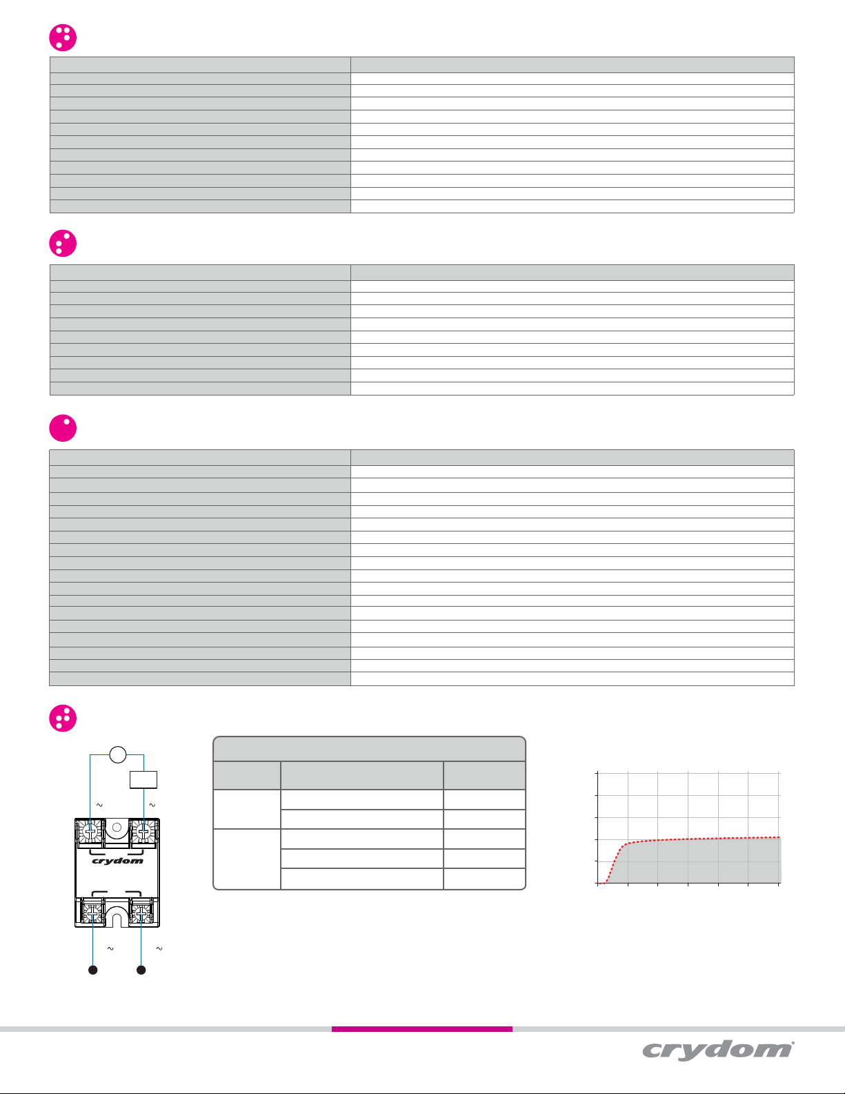
WIRING DIAGRAM
AC
V
(12)
Load
1 ( ) 2 ( )
2
OUTPUT
1
SOLI D S T AT E R ELA Y
4
INPUT
3
4 (– / ) 3 (+ / )
Copyright © 2021 Sensata Technologies, Inc.
Terminals
Input
Output
Recommended Wire Sizes
Wire Size
(Solid / Stranded)
24 AWG (0.2 mm
2 x 12 AWG (3.3 mm
20 AWG (0.5 mm
2 x 10 AWG (5.3 mm
2 x 8 AWG (8.4 mm
2
) / 0.2 [minimum]
2
2
) / 0.518 [minimum]
2
2
) / 8.4 [maximum]
) / 3.3 [maximum]
) / 5.3
www.sensata.com
Wire Pull-Out
Strength (lb)[N]
10 [44.5]
90 [400]
30 [133]
110 [490]
90 [400]
Input Current vs Input Voltage
Standard Regulated DC Input
25
20
15
10
Input Current (mA)
5
0
0 5 10 15 20 25 30
DC Input Voltage
Page 2
Page 3

EQUIVALENT CIRCUIT BLOCK DIAGRAMS
Diagram: HAxxxx
4
AC
AC
3
AC/DC
Converter
Current
Limiter
(13)
Trigger
Circuit
MECHANICAL SPECIFICATIONS
Tolerances: ±0.02 in / 0.5 mm
All dimensions are in: inches [millimeters]
Screw Termination
1.1
1.88
[47.6]
[27.9]
0.49
[12.4]
OUTPUT
1
S OLID S T A T E R ELA Y
4
INPUT
1.0
[25.4]
1.75
[44.5]
Mounting
Hole/Slot
0.19 [4.9]
DIA.
2
1.7
[43.2]
3
(14)
0.89
[22.6]
Diagram: HDxxxx
(15)
1
AC
AC
2
-
+DC
4
DC
(13)
3
Current
Limiter
Trigger
Circuit
(14)
(15)
1
AC
2
AC
(5)
(2)
1.04
[26.4]
0.93
[23.6]
(4 places)
1.0
[25.4]
(2 places)
2.25
[57.3]
2.25
[57.3]
1.88
[47.6]
Hex Standoff Termination (“K” Option)
1.1
[27.9]
0.49
[12.4]
OUTPUT
1
S OLID S T A T E R ELA Y
4
INPUT
1.0
[25.4]
1.75
[44.5]
Mounting
Hole/Slot
0.19 [4.9]
DIA.
2
1.7
[43.2]
3
Quick Connect Termination (“F” Option) - Up to 25 Amp (1)
Mounting
Hole/Slot
0.19 [4.9]
DIA.
1.88
[47.6]
1.58
[40.2]
0.49
[12.4]
OUTPUT
1
S OLID S T A T E R ELA Y
4
INPUT
1.40
[35.6]
1.75
[44.5]
Faston Terminal(16)
0.25 x 0.032
(2 places)
2
3
Faston Terminal(16)
1.7
[43.2]
0.187 x 0.020
(2 places)
1.31
[33.4]
1.25
[31.8]
2.25
[57.3]
Quick Connect Termination (“F” Option) - Up to 50 Amp (1)
Faston Terminal(16)
[11.4]
(2 places)
2
3
Faston Terminal(16)
0.25 x 0.032
(4 places)
0.45
1.7
[43.2]
0.187 x 0.020
(2 places)
Mounting
Hole/Slot
0.19 [4.9]
DIA.
1.88
[47.6]
1.58
[40.2]
0.63
[16.0]
OUTPUT
1
S OLID S T A T E R ELA Y
4
INPUT
0.49
[12.4]
1.40
[35.6]
1.75
[44.5]
1.31
[33.4]
2.25
[57.3]
1.25
[31.8]
Copyright © 2021 Sensata Technologies, Inc.
Page 3
www.sensata.com
Page 4

SURGE CURRENT INFORMATION
120
100
80
60
40
20
Surge Current (Amp)
0
0.01 0.1 1 10
Surge Duration (Secs)
50 A
12 A
600
500
400
300
200
100
Surge Current (Amp)
0
0.01 0.1 1 10
Surge Duration (Secs)
90 A
1200
1050
900
750
600
450
300
Surge Current (Amp)
150
0
0.01 0.1 1 10
Surge Duration (Secs)
250
200
150
100
50
Surge Current (Amp)
0
0.01 0.1 1 10
Surge Duration (Secs)
75 A
25 A
900
800
700
600
500
400
300
200
Surge Current (Amp)
100
0
0.01 0.1 1 10
Surge Duration (Secs)
110 A
1500
1200
900
600
300
Surge Current (Amp)
0
0.01 0.1 1 10
Surge Duration (Secs)
1800
1600
1400
1200
1000
Surge Current (Amp)
Non repetitive peak surge current at Tj initial 40ºC.
125 A
800
600
400
200
0
0.01 0.1 1 10
Surge Duration (Secs)
Page 4
Copyright © 2021 Sensata Technologies, Inc.
www.sensata.com
Page 5

THERMAL DERATE INFORMATION
12 A
3ºC/W
12
10
8
6
4
2
Load Current (Amps)
0
20 30 40 50 60 70 80
Ambient Temperature (ºC)
5ºC/W
No heatsink
75 A
0.5ºC/W
75
60
45
30
15
Load Current (Amps)
0
20 30 40 50 60 70 80
0.7ºC/W
Ambient Temperature (ºC)
1ºC/W
1.5ºC/W
25 A
1.5ºC/W
25
20
15
10
5
Load Current (Amps)
0
20 30 40 50 60 70 80
Ambient Temperature (ºC)
2ºC/W
3ºC/W
90 A
0.5ºC/W
90
80
70
60
50
40
30
20
10
Load Current (Amps)
0
20 30 40 50 60 70 80
0.7ºC/W
Ambient Temperature (ºC)
1ºC/W
125 A
0.5ºC/W
120
100
80
60
40
20
Load Current (Amps)
0
20 30 40 50 60 70 80
0.7ºC/W
Ambient Temperature (ºC)
1ºC/W
1.5ºC/W
50 A
0.7ºC/W
50
40
30
20
10
Load Current (Amps)
0
20 30 40 50 60 70 80
1ºC/W
Ambient Temperature (ºC)
1.5ºC/W
110 A
0.5ºC/W
120
100
80
60
40
20
Load Current (Amps)
0
20 30 40 50 60 70 80
0.7ºC/W
Ambient Temperature (ºC)
1ºC/W
2ºC/W
1.5ºC/W
GENERAL NOTES
(1) Single pair (up to 25A) Double pair* (up to 50A). *Caution: User must connect both pairs.
(2)
Option “K” is designed and tested for use with printed circuit boards or ring/fork terminals having a thickness between 0.031 and 0.093 inches (0.79 to 2.36 mm), and loads rated up to 50
Amps. For higher load currents, the “K” standoff temperature must not exceed 105°C. For additional application assistance please contact Crydom Technical Support.
(3) Output will self trigger between 900-1200Vpk, Min. power factor 0.7 or higher, not suituable for capacitive loads.
(4) Instantaneous turn-on version is not recomended for capacitive loads. Use zero turn-on only.
(5) All parameters at 25°C unless otherwise specified.
(6) For “S” option, operating voltage frequency is 47-63Hz.
(7) For parts with option “S” maximum leakage current is 10mA.
(8) Heat sinking required, see derating curves.
(9) Increase minimum voltage by 1V for operations from -20 to -40°C.
(10)
Turn-on time for instantaneous turn-on versions is 0.02 msec (DC Control Models)
(11)
All parameters at 50% power rating and 100% duty cycle (contact Crydom tech support for detailed report).
(12) Load can be wired to either SSR output terminal 1 or 2.
(13) Elective Input Status LED, “G” option
(14) Elective Overvoltage Protection, “P” option.
(15)
Elective Internal Snubber, “S” option.
(16)
Mechanical dimensions vary from G3 models.
For additional information or specific questions, contact Crydom Technical Support.
Copyright © 2021 Sensata Technologies, Inc.
www.sensata.com
Page 5
Page 6

AGENCY APPROVALS AND CERTIFICATIONS
Designed in accordance with the requirements of IEC 62314
IEC 61000-4-2 : Electrostatic Discharge – Level 3
IEC 61000-4-4 : Electrically Fast Transients – Level 3
IEC 61000-4-5 : Electrical Surges – Level 3
IEC 600068-2-6: Vibration 0.33mm and 0.75mm Amplitude over 10-55 Hz
IEC 600068-2-27: Shock Resistance 15g/11ms
E116949
(exept 110A & 125A models)
ACCESORIES
Protective Cover & Hardware Kits
Protective Cover
Part number: KS101
Clear plastic cover compatible with all new
S1 designs. Safety covers provide added
protection from electric shock when
installing or checking equipment.
Hardware Kit
Part number: HK4
Bag with 2 square brass accessories and 2
screw 8-32 x 5/8 for output. Used to mount
TMR1 lug terminals.
LR81689 (except 12, 110 and 125A models)E116950 (110 and 125A models)
Cover Hardware
KS101 HK1
Kit
HK4
Recommended Accessories
Heat Sink
Part No.
HS501DR
HS301 / HS301DR
HS251
HS202 / HS202DR
HS201 / HS201DR
HS172
HS151 / HS151DR
HS122 / HS122DR
HS103 / HS103DR
HS101
HS073
HS072
HS053
HS033
HS023
Thermal Resistance
[ºC/W]
5.0
3.0
2.5
2.0
2.0
1.7
1.5
1.2
1.0
1.0
0.7
0.7
0.5
0.36
0.25
Lug Terminal Thermal Pad
TRM1
TRM6
HSP-1
HSP-2
Copyright © 2021 Sensata Technologies, Inc.
Page 6
www.sensata.com
Page 7

www.sensata.comCopyright © 2021 Sensata Technologies, Inc.
WARNINGS
RISK OF MATERIAL DAMAGE AND HOT ENCLOSURE
• The product’s side panels may be hot, allow the product to cool before touching.
• Follow proper mounting instructions including torque values.
• Do not allow liquids or foreign objects to enter this product.
Failure to follow these instructions can result in serious injury, or equipment damage.
HAZARD OF ELECTRIC SHOCK, EXPLOSION OR ARC FLASH
• Disconnect all power before installing or working with this equipment.
• Verify all connections and replace all covers before turning on power.
Failure to follow these instructions will result in death or serious injury.
Sensata Technologies, Inc. (“Sensata”) data sheets are solely intended to assist designers (“Buyers”) who are developing systems that
incorporate Sensata products (also referred to herein as “components”). Buyer understands and agrees that Buyer remains responsible
for using its independent analysis, evaluation and judgment in designing Buyer’s systems and products. Sensata data sheets have
been created using standard laboratory conditions and engineering practices. Sensata has not conducted any testing other than that
specifically described in the published documentation for a particular data sheet. Sensata may make corrections, enhancements,
improvements and other changes to its data sheets or components without notice.
Buyers are authorized to use Sensata data sheets with the Sensata component(s) identified in each particular data sheet. HOWEVER, NO
OTHER LICENSE, EXPRESS OR IMPLIED, BY ESTOPPEL OR OTHERWISE TO ANY OTHER SENSATA INTELLECTUAL PROPERTY RIGHT, AND
NO LICENSE TO ANY THIRD PARTY TECHNOLOGY OR INTELLECTUAL PROPERTY RIGHT, IS GRANTED HEREIN. SENSATA DATA SHEETS
ARE PROVIDED “AS IS”. SENSATA MAKES NO WARRANTIES OR REPRESENTATIONS WITH REGARD TO THE DATA SHEETS OR USE
OF THE DATA SHEETS, EXPRESS, IMPLIED OR STATUTORY, INCLUDING ACCURACY OR COMPLETENESS. SENSATA DISCLAIMS
ANY WARRANTY OF TITLE AND ANY IMPLIED WARRANTIES OF MERCHANTABILITY, FITNESS FOR A PARTICULAR PURPOSE, QUIET
ENJOYMENT, QUIET POSSESSION, AND NON-INFRINGEMENT OF ANY THIRD PARTY INTELLECTUAL PROPERTY RIGHTS WITH REGARD
TO SENSATA DATA SHEETS OR USE THEREOF.
All products are sold subject to Sensata’s terms and conditions of sale supplied at www.sensata.com SENSATA ASSUMES NO LIABILITY
FOR APPLICATIONS ASSISTANCE OR THE DESIGN OF BUYERS’ PRODUCTS. BUYER ACKNOWLEDGES AND AGREES THAT IT IS SOLELY
RESPONSIBLE FOR COMPLIANCE WITH ALL LEGAL, REGULATORY AND SAFETY-RELATED REQUIREMENTS CONCERNING ITS PRODUCTS,
AND ANY USE OF SENSATA COMPONENTS IN ITS APPLICATIONS, NOTWITHSTANDING ANY APPLICATIONS-RELATED INFORMATION
OR SUPPORT THAT MAY BE PROVIDED BY SENSATA.
Mailing Address: Sensata Technologies, Inc., 529 Pleasant Street, Attleboro, MA 02703, USA.
Rev. 04/01/21 ECN 21039 FDE-07-01 Rev. B
Page 7
CONTACT US
Americas
+1 (877) 502 5500 – Option 2
sales.crydom@sensata.com
Europe, Middle East & Africa
+44 (1202) 416170
ssr-info.eu@sensata.com
Asia Pacific
sales.isasia@list.sensata.com
China +86 (21) 2306 1500
Japan +81 (45) 277 7117
Korea +82 (31) 601 2004
India +91 (80) 67920890
Rest of Asia +886 (2) 27602006
ext 2808
 Loading...