

Page 1
1-373
H
Optically Coupled 20 mA
Current Loop Receiver
Technical Data
HCPL-4200
Features
• Data Output Compatible
with LSTTL, TTL and CMOS
• 20 K Baud Data Rate at 1400
Metres Line Length
• Guaranteed Performance
over Temperature (0°C to
70°C)
• Guaranteed On and Off
Thresholds
• LED is Protected from
Excess Current
• Input Threshold Hysteresis
• Three-State Output Compatible with Data Buses
• Internal Shield for High
Common Mode Rejection
• Safety Approval
UL Recognized -2500 V rms,
for 1 Minute
CSA Approved
• Optically Coupled 20 mA
Current Loop Transmitter,
HCPL-4100, Also Available
Applications
• Isolated 20 mA Current
• Loop Receiver in:
Computer Peripherals
Industrial Control Equipment
Data Communications
Equipment
Description
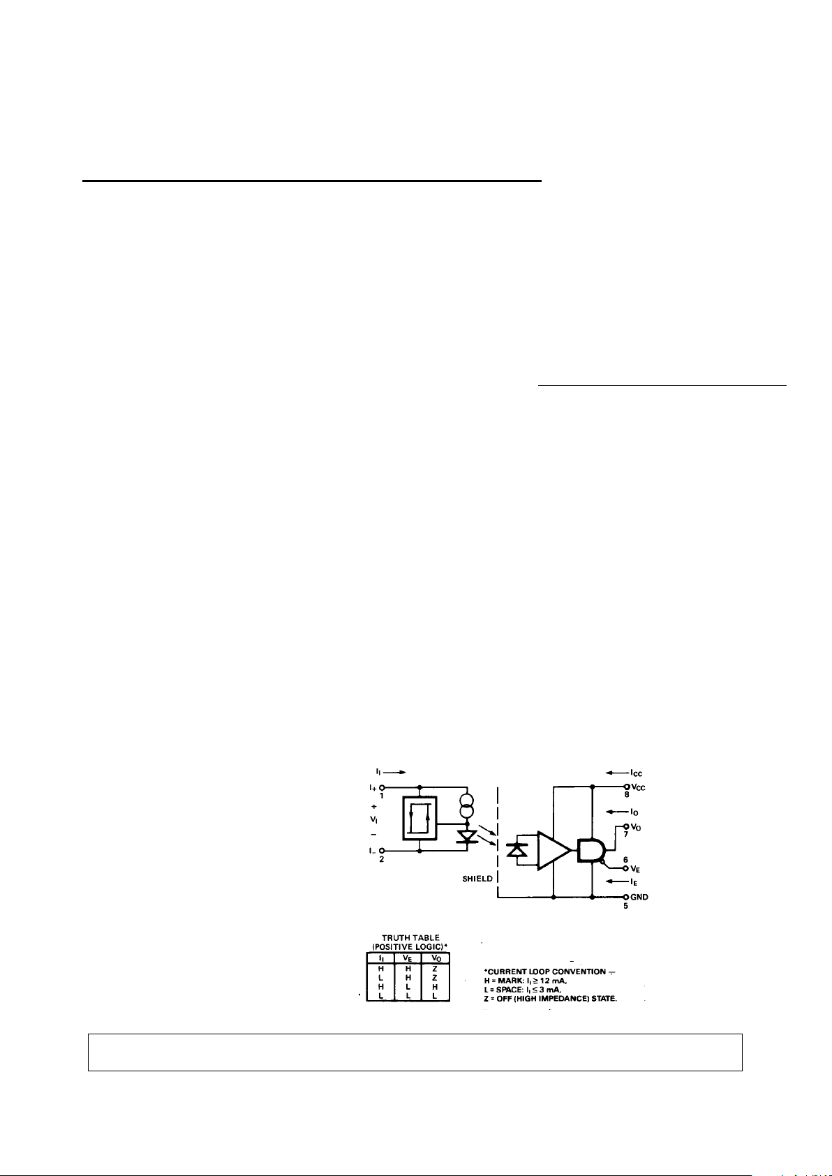
The HCPL-4200 optocoupler is
designed to operate as a receiver
in equipment using the 20 mA
Current Loop. 20 mA current
loop systems conventionally signal a logic high state by transmitting 20 mA of loop current
(MARK), and signal a logic low
state by allowing no more than a
few milliamperes of loop current
(SPACE). Optical coupling of the
signal from the 20 mA current
loop to the logic output breaks
ground loops and provides for a
very high common mode
rejection. The HCPL-4200 aids in
the design process by providing
guaranteed thresholds for logic
high state and logic low state for
the current loop, providing an
LSTTL, TTL, or CMOS compatible
logic interface, and providing
guaranteed common mode
rejection. The buffer circuit on
the current loop side of the
HCPL-4200 provides typically 0.8
mA of hysteresis which increases
the immunity to common mode
and differential mode noise. The
buffer also provides a controlled
amount of LED drive current
which takes into account any
LED light output degradation.
The internal shield allows a
guaranteed 1000 V/µs common
mode transient immunity.
CAUTION: It is advised that normal static precautions be taken in handling and assembly of this component to
prevent damage and/or degradation which may be induced by ESD.
Functional Diagram
A 0.1 µF bypass capacitor connected between pins 8 and 5 is recommended.
5965-3580E
Page 2
1-374
Ordering Information
Specify part number followed by Option Number (if desired).
HCPL-4200# XXX
300 = Gull Wing Surface Mount Lead Option
500 = Tape/Reel Package Option (1 K min)
Option data sheets available. Contact your Hewlett-Packard sales representative or authorized distributor for
information.
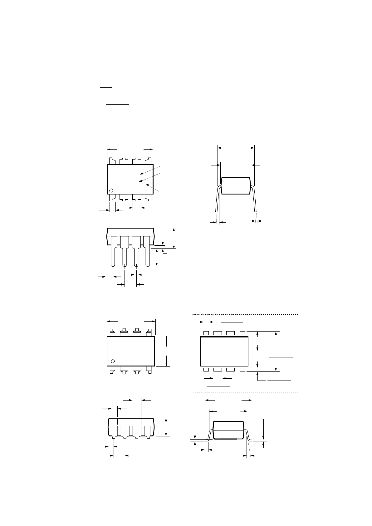
Package Outline Drawings – 8 Pin DIP Package (HCPL-4200)
8 Pin DIP Package with Gull Wing Surface Mount Option 300 (HCPL-4200)
0.635 ± 0.25
(0.025 ± 0.010)
12° NOM.
9.65 ± 0.25
(0.380 ± 0.010)
0.635 ± 0.130
(0.025 ± 0.005)
7.62 ± 0.25
(0.300 ± 0.010)
5
6
7
8
4
3
2
1
9.65 ± 0.25
(0.380 ± 0.010)
6.350 ± 0.25
(0.250 ± 0.010)
1.016 (0.040)
1.194 (0.047)
1.194 (0.047)
1.778 (0.070)
9.398 (0.370)
9.906 (0.390)
4.826
(0.190)
TYP.
0.381 (0.015)
0.635 (0.025)
PAD LOCATION (FOR REFERENCE ONLY)
1.080 ± 0.320
(0.043 ± 0.013)
4.19
(0.165)
MAX.
1.780
(0.070)
MAX.
1.19
(0.047)
MAX.
2.54
(0.100)
BSC
DIMENSIONS IN MILLIMETERS (INCHES).
LEAD COPLANARITY = 0.10 mm (0.004 INCHES).
0.254
+ 0.076
- 0.051
(0.010
+ 0.003)
- 0.002)
9.65 ± 0.25
(0.380 ± 0.010)
1.78 (0.070) MAX.
1.19 (0.047) MAX.
HP XXXX
YYWW
DATE CODE
1.080 ± 0.320
(0.043 ± 0.013)
2.54 ± 0.25
(0.100 ± 0.010)
0.51 (0.020) MIN.
0.65 (0.025) MAX.
4.70 (0.185) MAX.
2.92 (0.115) MIN.
DIMENSIONS IN MILLIMETERS AND (INCHES).
5678
4321
5° TYP.
TYPE NUMBER
UL
RECOGNITION
UR
0.254
+ 0.076
- 0.051
(0.010
+ 0.003)
- 0.002)
7.62 ± 0.25
(0.300 ± 0.010)
6.35 ± 0.25
(0.250 ± 0.010)
Page 3
1-375
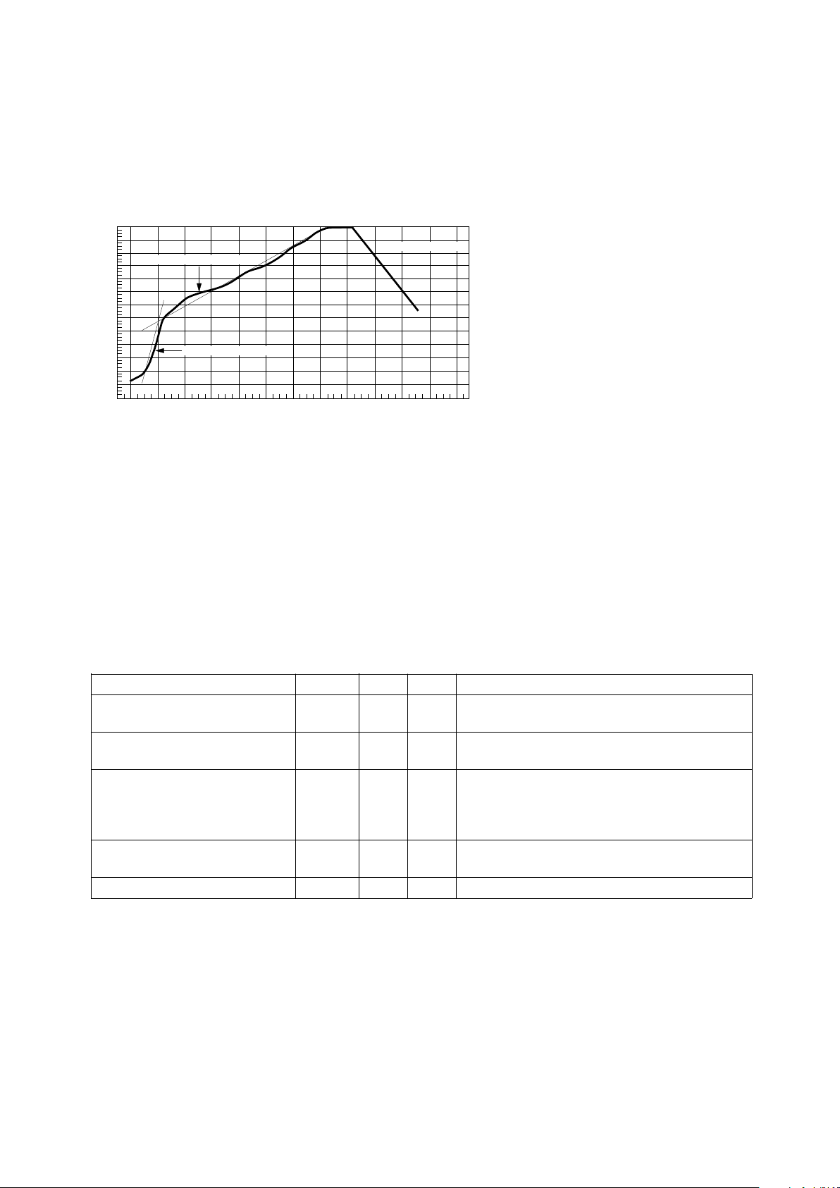
Thermal Profile (Option #300)
240
∆T = 115°C, 0.3°C/SEC
0
∆T = 100°C, 1.5°C/SEC
∆T = 145°C, 1°C/SEC
TIME – MINUTES
TEMPERATURE – °C
220
200
180
160
140
120
100
80
60
40
20
0
260
123456789101112
Figure 1. Maximum Solder Reflow Thermal Profile.
(Note: Use of non-chlorine activated fluxes is recommended.)
Regulatory Information
The HCPL-4200 has been
approved by the following
organizations:
UL
Recognized under UL 1577,
Component Recognition
Program, File E55361.
CSA
Approved under CSA Component
Acceptance Notice #5, File CA
88324.
Insulation and Safety Related Specifications
Parameter Symbol Value Units Conditions
Min. External Air Gap L(IO1) 7.1 mm Measured from input terminals to output
(External Clearance) terminals, shortest distance through air
Min. External Tracking Path L(IO2) 7.4 mm Measured from input terminals to output
(External Creepage) terminals, shortest distance path along body
Min. Internal Plastic Gap 0.08 mm Through insulation distance, conductor to
(Internal Clearance) conductor, usually the direct distance
between the photoemitter and photodetector
inside the optocoupler cavity
Tracking Resistance CTI 200 volts DIN IEC 112/VDE 0303 PART 1
(Comparative Tracking Index)
Isolation Group IIIa Material Group (DIN VDE 0110, 1/89, Table 1)
Option 300 – surface mount classification is Class A in accordance with CECC 00802.
Page 4
1-376
Absolute Maximum Ratings
(No Derating Required up to 70°C)
Storage Temperature .................................................. -55°C to +125°C
Operating Temperature ................................................. -40°C to +85°C
Lead Solder Temperature .... 260°C for 10 s (1.6 mm below seating plane)
Supply Voltage – VCC.............................................................. 0 V to 20 V
Average Input Current - II........................................... -30 mA to 30 mA
Peak Transient Input Current - II............................................... 0.5 A
[1]
Enable Input Voltage – VE................................................ -0.5 V to 20 V
Output Voltage – VO........................................................ -0.5 V to 20 V
Average Output Current – IO.......................................................25 mA
Input Power Dissipation – PI................................................... 90 mW
[2]
Output Power Dissipation – PO............................................. 210 mW
[3]
Total Power Dissipation – P .................................................. 255 mW
[4]
Infrared and Vapor Phase Reflow Temperature
(Option #300) ..........................................see Fig. 1, Thermal Profile
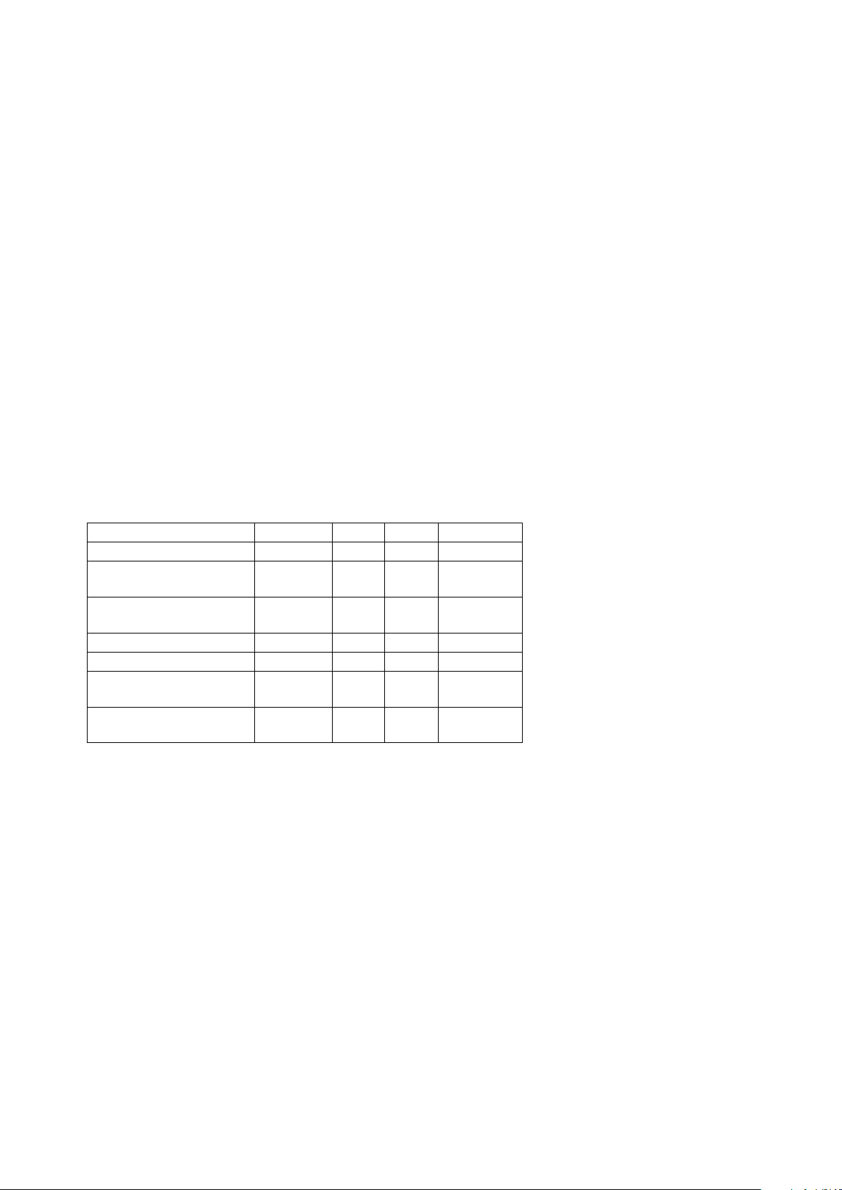
Recommended Operating Conditions
Parameter Symbol Min. Max. Units
Power Supply Voltage V
CC
4.5 20 Volts
Forward Input Current I
SI
0 2.0 mA
(SPACE)
Forward Input Current I
MI
14 24 mA
(MARK)
Operating Temperature T
A
070 °C
Fan Out N 0 4 TTL Loads
Logic Low Enable V
EL
0 0.8 Volts
Voltage
Logic High Enable V
EH
2.0 20 Volts
Voltage
Page 5
1-377
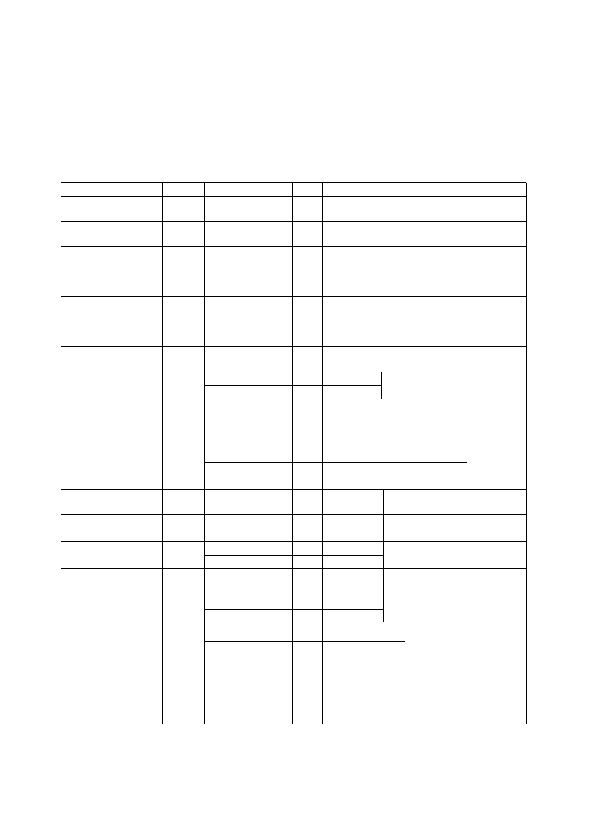
DC Electrical Specifications
For 0°C ≤ TA ≤ 70°C, 4.5 V ≤ VCC ≤ 20 V, VE = 0.8 V, all typicals at TA = 25°C and VCC = 5 V unless otherwise
noted. See note 13.
Parameter Symbol Min. Typ. Max. Units Test Conditions Fig. Note
Mark State Input I
MI
12 mA 2, 3,
Current 4
Mark State Input V
MI
2.52 2.75 Volts II = 20 mA VE = Don’t Care 4, 5
Voltage
Space State Input I
SI
3 mA 2, 3,
Current 4
Space State Input V
SI
1.6 2.2 Volts II = 0.5 to 2.0 mA VE = Don’t 2, 4
Voltage Care
Input Hysteresis I
HYS
0.3 0.8 mA 2
Current
Logic Low Output V
OL
0.5 Volts IOL = 6.4 mA II = 3 mA 6
Voltage (4 TTL Loads)
Logic High Output V
OH
2.4 Volts IOH = -2.6 mA, II = 12 mA 7
Voltage
Output Leakage I
OHH
100 µAVO = 5.5 V II = 20 mA
500 µAVO = 20 V
Logic High Enable V
EH
2.0 Volts
Voltage
Logic Low Enable V
EL
0.8 Volts
Voltage
Logic High Enable I
EH
20 µAVE = 2.7 V
100 µAVE = 5.5 V
0.004 250 µAVE = 20 V
Logic Low Enable I
EL
-0.32 mA VE = 0.4 V
Current
Logic Low Supply I
CCL
4.5 6.0 mA VCC = 5.5 V II = 0 mA
5.25 7.5 mA VCC = 20 V
Logic High Supply I
CCH
2.7 4.5 mA VCC = 5.5 V II = 20 mA
3.1 6.0 mA VCC = 20 V
High Impedance I
OZL
-20 µAVO = 0.4 V VE = 2 V,
I
OZH
20 µAVO = 2.4 V
100 µAVO = 5.5 V
500 µAVO = 20 V
Logic Low Short I
OSL
25 mA VO = VCC = 5.5 V II = 0 mA 5
40 mA VO = VCC = 20 V
Logic High Short I
OSH
-10 mA VCC = 5.5 V II = 20 mA 5
-25 mA VCC = 20 V
Input Capacitance C
IN
120 pF f = 1 MHz, VI = 0 V dc,
Pins 1 and 2
Current (V
OUT
> VCC)
Current
Current
State Output
Current
Current
Circuit Output
Current
Circuit Output
Current
II = 20 mA
VO = GND
VCC = 4.5 V
VE = Don’t Care
VE = Don’t Care
Page 6
1-378
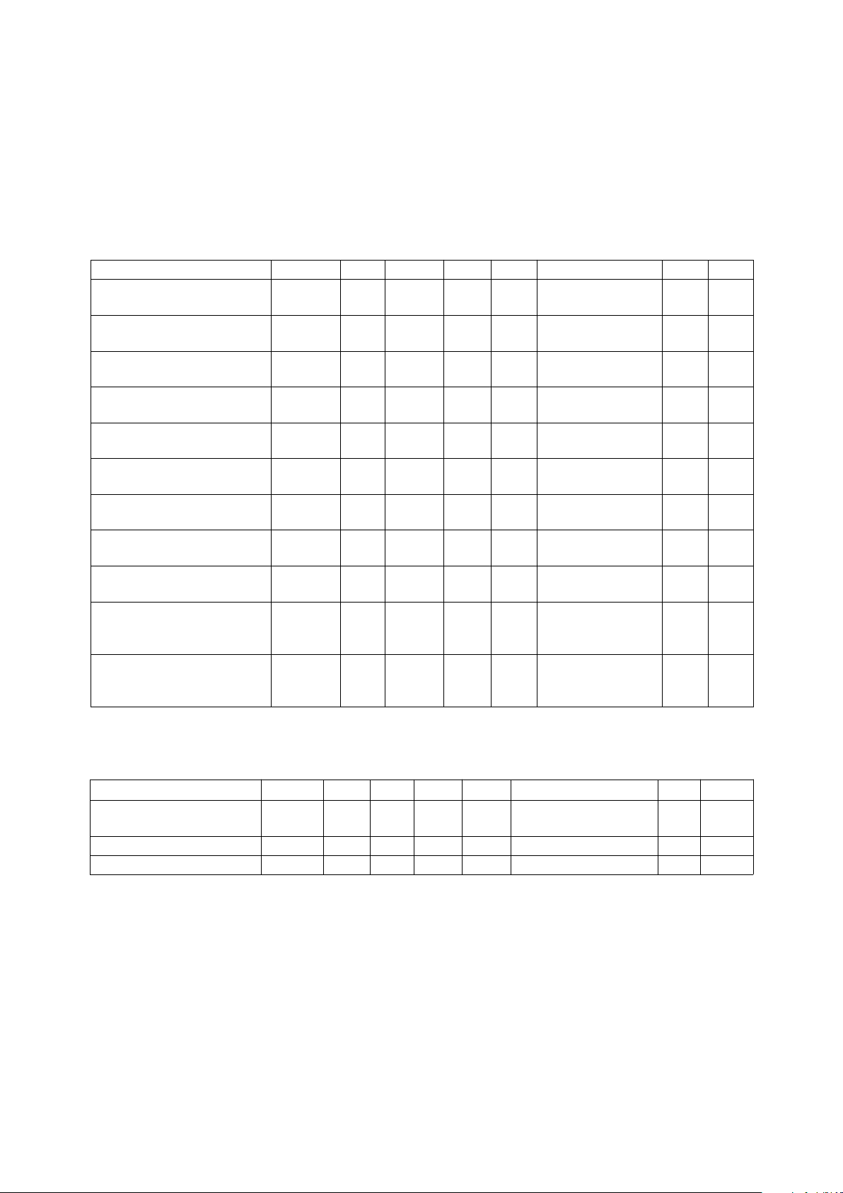
Switching Specifications
For 0°C ≤ TA ≤ 70°C, 4.5 V ≤ VCC ≤ 20 V, VE = 0.8 V, all typicals at TA = 25°C and VCC = 5 V unless
otherwise noted. See note 13.
Parameter Symbol Min. Typ. Max. Units Test Conditions Fig. Note
Propagation Delay Time t
PLH
0.23 1.6 µsVE = 0 V, 8, 9, 7
to Logic High Output Level CL = 15 pF 10
Propagation Delay Time t
PHL
0.17 1.0 µsVE = 0 V, 8, 9, 8
to Logic Low Output Level CL = 15 pF 10
Propagation Delay Time t
PLH
- t
PHL
60 ns II = 20 mA, 8, 9,
Skew CL = 15 pF 10
Output Enable Time to t
PZL
25 ns II = 0 mA, 12, 13,
Logic Low Level CL = 15 pF 15
Output Enable Time to t
PZH
28 ns II = 20 mA, 12, 13,
Logic High Level CL = 15 pF 14
Output Disable Time to t
PLZ
60 ns II = 0 mA, 12, 13,
Logic Low Level CL = 15 pF 15
Output Disable Time to t
PHZ
105 ns II = 20 mA, 12, 13,
Logic High Level CL = 15 pF 14
Output Rise Time t
r
55 ns VCC = 5 V, 8, 9, 9
(10-90%) CL = 15 pF 11
Output Fall Time t
f
15 ns VCC = 5 V, 8, 9, 10
(90-10%) CL = 15 pF 11
Common Mode Transient |CMH| 1,000 10,000 V/µsVCM = 50 V (peak) 16 11
Immunity at Logic High II = 12 mA,
Output Level TA = 25°C
Common Mode Transient |CML| 1,000 10,000 V/µsVCM = 50 V (peak) 16 12
Immunity at Logic Low II = 3 mA,
Output Level TA = 25°C
Package Characteristics
For 0°C ≤ TA ≤ 70°C, unless otherwise specified. All typicals at TA = 25°C.
Parameter Symbol Min. Typ. Max. Units Test Conditions Fig. Notes
Input-Output Momentary V
ISO
2500 V rms RH ≤ 50%, t = 1 min, 6, 14
Withstand Voltage* TA = 25°C
Resistance, Input-Output R
I-O
10
12
ohms V
I-O
= 500 V dc 6
Capacitance, Input-Output C
I-O
1.0 pF f = 1 MHz, V
I-O
= 0 V 6
*The Input-Output Momentary Withstand Voltage is a dielectric voltage rating that should not be interpreted as an input-output
continuous voltage rating. For the continuous voltage rating refer to the VDE 0884 Insulation Characteristics Table (if applicable),
your equipment level safety specification, or HP Application Note 1074, “Optocoupler Input-Output Endurance Voltage.”
Page 7
1-379
Notes:
1. ≤ 1 µs pulse width, 300 pps.
2. Derate linearly above 70°C free air
temperature at a rate of 1.6 mW/°C.
Proper application of the derating
factors will prevent IC junction
temperatures from exceeding 125°C
for ambient temperatures up to 85°C.
3. Derate linearly above 70°C free air
temperature at a rate of 3.8 mW/°C.
4. Derate linearly above 70°C free air
temperature at a rate of 4.6 mW/°C.
5. Duration of output short circuit time
shall not exceed 10 ms.
6. The device is considered a two
terminal device, pins 1, 2, 3, and 4
are connected together and pins 5, 6,
7, and 8 are connected together.
7. The t
PLH
propagation delay is
measured from the 10 mA level on
the leading edge of the input pulse to
the 1.3 V level on the leading edge of
the output pulse.
8. The t
PHL
propagation delay is
measured from the 10 mA level on
the trailing edge of the input pulse to
the 1.3 V level on the trailing edge of
the output pulse.
9. The rise time, tr, is measured from the
10% to the 90% level on the rising
edge of the output logic pulse.
10. The fall time, tf, is measured from the
90% to the 10% level on the falling
edge of the output logic pulse.
11. Common mode transient immunity in
the logic high level is the maximum
(negative) dVCM/dt on the trailing
edge of the common mode pulse,
VCM, which can be sustained with the
output voltage in the logic high state
(i.e., VO ≥ 2 V).
12. Common mode transient immunity in
the logic low level is the maximum
(positive) dVCM/dt on the leading
edge of the common mode pulse,
VCM, which can be sustained with the
output voltage in the logic low state
(i.e., VO ≤ 0.8 V).
13. Use of a 0.1 µF bypass capacitor
connected between pins 5 and 8 is
recommended.
14. In accordance with UL 1577, each
optocoupler momentary withstand is
proof tested by applying an insulation
test voltage ≥ 3000 V rms for 1
second (leakage detection current
limit, I
i-o
≤ 5 µA).
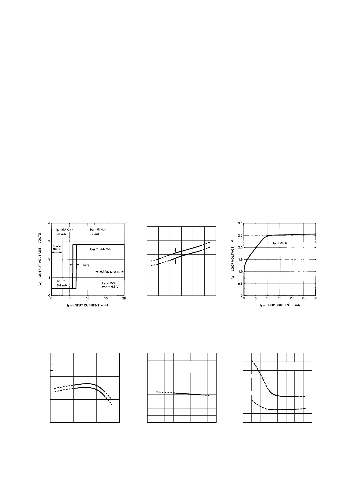
Figure 5. Typical Input Voltage vs.
Temperature.
Figure 6. Typical Logic Low Output
Voltage vs. Temperature.
Figure 7. Typical Logic High Output
Current vs. Temperature.
V
I
– LOOP VOLTAGE – VOLTS
-50 100
2.8
2.2
T
A
– AMBIENT TEMPERATURE –°C
-25 0 25
2.6
50 75
2.4
II = 12 mA
II = 20 mA
V
OL
– LOW LEVEL OUTPUT VOLTAGE – V
-60 100
1.0
0
T
A
– TEMPERATURE –°C
-40 0 20
0.7
60 80
0.3
40-20
0.9
0.8
0.6
0.5
0.4
0.2
0.1
V
CC
= 4.5 V
I
I
= 3 mA
I
O
= 6.4 mA
I
OH
– HIGH LEVEL OUTPUT CURRENT – mA
-60 100
0
-8
T
A
– TEMPERATURE –°C
-40 0 20
-3
60 80
-6
40-20
-1
-2
-4
-5
-7
V
CC
= 4.5 V
I
I
= 12 mA
VO = 2.7 V
VO = 2.4 V
Figure 2. Typical Output Voltage vs.
Loop Current.
Figure 3. Typical Current Switching
Threshold vs. Temperature.
I
I
– INPUT SWITCHING THRESHOLD – mA
-50 100
10
0
T
A
– AMBIENT TEMPERATURE –°C
-25 0 25
6
2
50 75
4
I
HYS
8
Figure 4. Typical Input Loop Voltage
vs. Input Current.
Page 8
1-380
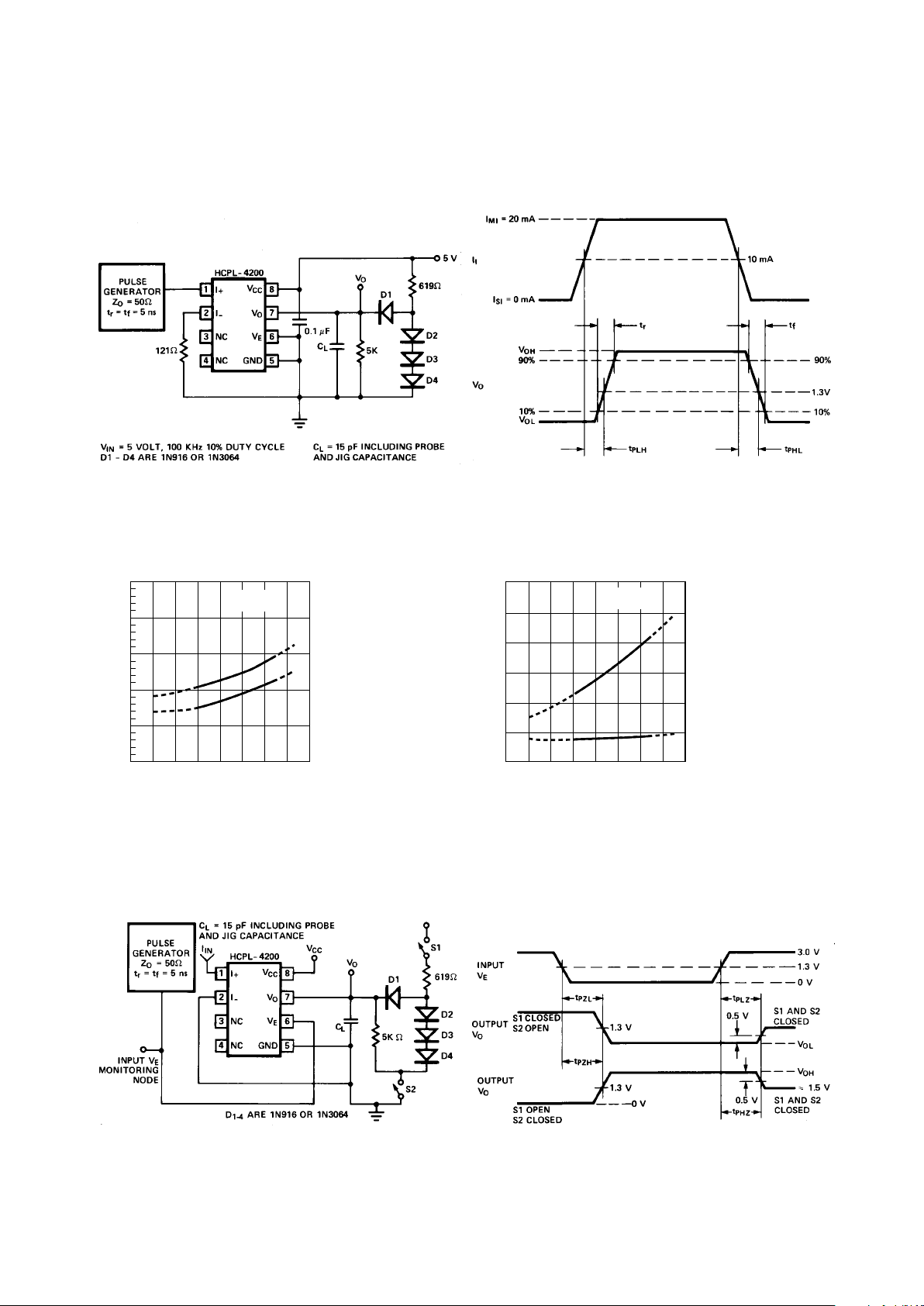
Figure 8. Test Circuit for t
PHL
, t
PLH
, tr, and tf.
Figure 13. Waveforms for t
PZH
, t
PZL
, t
PHZ
, and t
PLZ
.Figure 12. Test Circuit for t
PZH
, t
PZL
, t
PHZ
, and t
PLZ
.
Figure 9. Waveforms for t
PHL
, t
PLH
, tr, and tf.
Figure 10. Typical Propagation Delay vs. Temperature.
t
p
– PROPAGATION DELAY – µs
-60 100
0.5
0
T
A
– TEMPERATURE –°C
-40 0 20
0.3
60 80
0.1
40-20
0.4
0.2
V
CC
= 5 V
C
L
= 15 pF
t
PLH
t
PHL
t
r
, t
f
– RISE, FALL TIMES – ns
-60 100
120
0
T
A
– TEMPERATURE –°C
-40 0 20 60 80
40-20
100
80
60
40
20
t
r
V
CC
= 5 V
C
L
= 15 pF
t
f
Figure 11. Typical Rise, Fall Time vs. Temperature.
+5 V
Page 9
1-381
t
p
– ENABLE PROPAGATION DELAY – ns
-60 100
200
0
T
A
– TEMPERATURE –°C
-40 0 20 60 80
40-20
150
100
50
V
CC
CL = 15 pF
t
PHZ
t
PZH
20 V
4.5 V
4.5 V
20 V
t
p
– ENABLE PROPAGATION DELAY – ns
-60 100
100
0
T
A
– TEMPERATURE –°C
-40 0 20 60 80
40-20
80
60
20
V
CC
CL = 15 pF
t
PLZ
t
PZL
20 V
4.5 V
4.5 V
20 V
40
Figure 14. Typical Logic High Enable Propagation Delay vs.
Temperature.
Figure 15. Typical Logic Low Enable Propagation Delay vs.
Temperature.
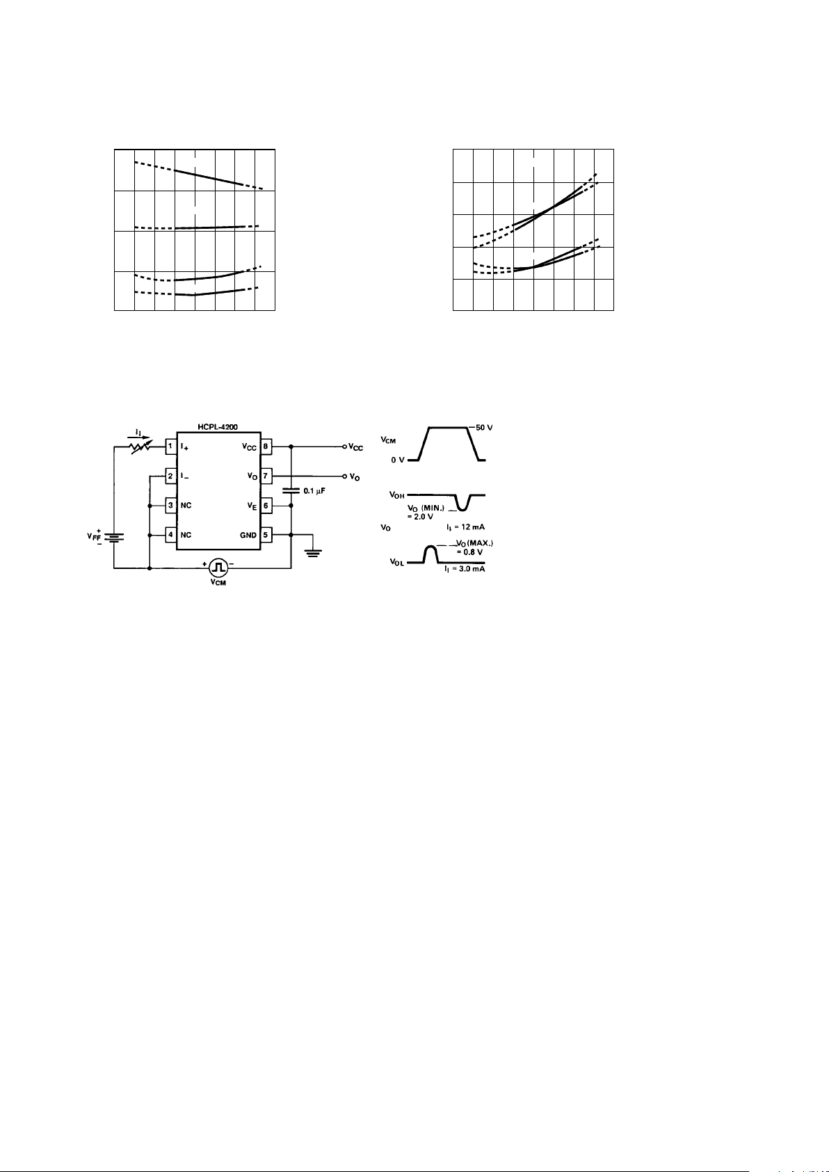
Figure 16. Test Circuit for Common Mode Transient
Immunity.
Applications
Data transfer between equipment
which employs current loop
circuits can be accomplished via
one of three configurations:
simplex, half duplex or full
duplex communication. With
these configurations, point-topoint and multidrop arrangements
are possible. The appropriate
configuration to use depends
upon data rate, number of
stations, number and length of
lines, direction of data flow,
protocol, current source location
and voltage compliance value,
etc.
Simplex
The simplex configuration,
whether point to point or multidrop, gives unidirectional data
flow from transmitter to
receiver(s). This is the simplest
configuration for use in long line
length (two wire), for high data
rate, and low current source
compliance level applications.
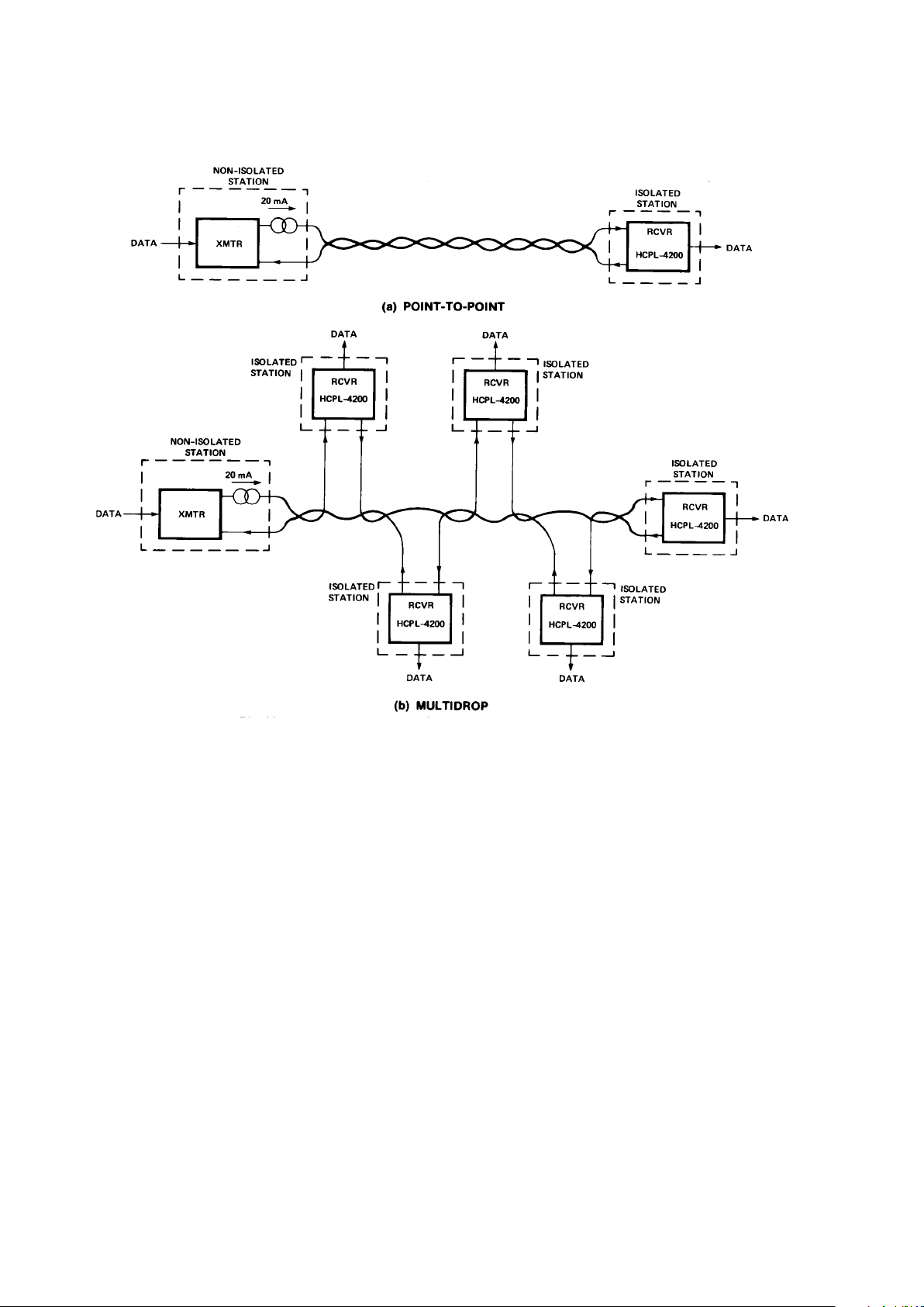
Block diagrams of simplex pointto-point and multidrop
arrangements are given in
Figures 17a and 17b respectively
for the HCPL-4200 receiver
optocoupler.
For the highest data rate performance in a current loop, the
configuration of a non-isolated
active transmitter (containing
current source) transmitting data
to a remote isolated receiver(s)
should be used. When the current
source is located at the transmitter end, the loop is charged
approximately to VMI (2.5 V).
Alternatively, when the current
source is located at the receiver
end, the loop is charged to the
full compliance voltage level. The
lower the charged voltage level
the faster the data rate will be. In
the configurations of Figures 17a
and 17b, data rate is independent
of the current source voltage
compliance level. An adequate
compliance level of current
source must be available for
voltage drops across station(s)
during the MARK state in multidrop applications or for long line
length. The maximum compliance
level is determined by the transmitter breakdown characteristic.
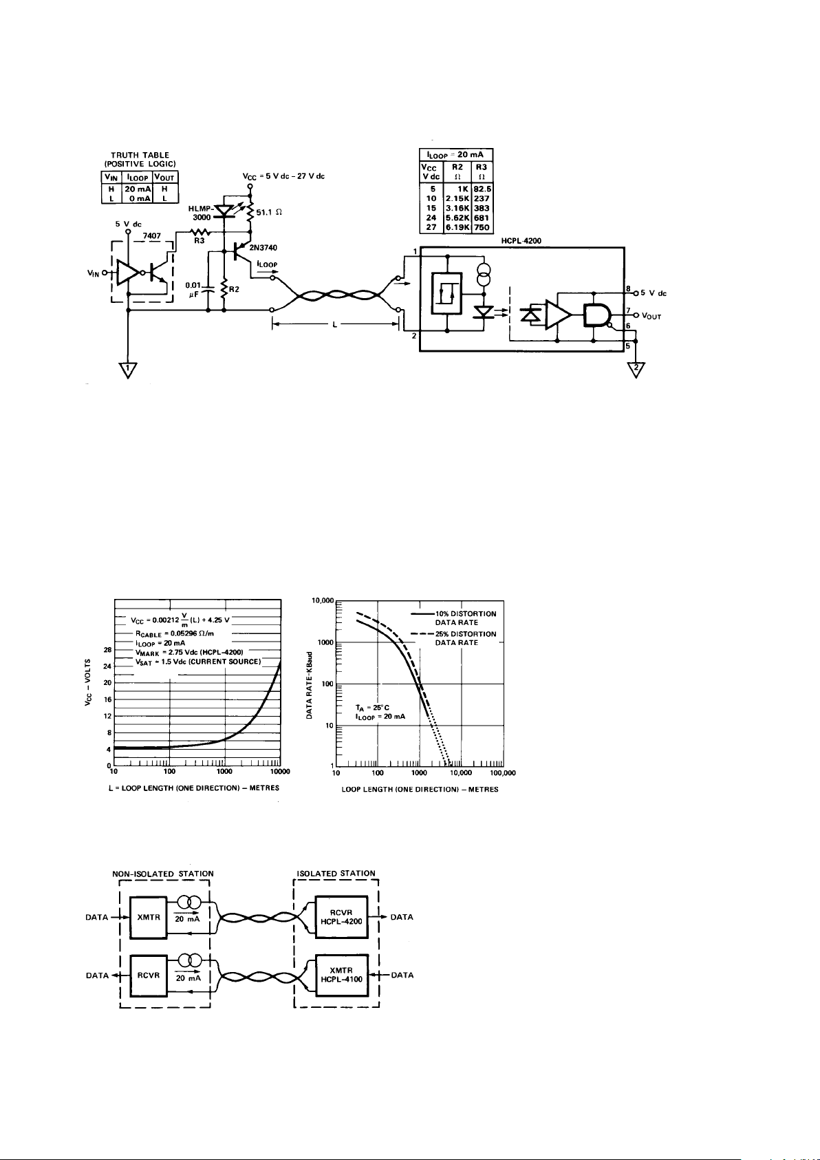
A recommended non-isolated
active transmitter circuit which
can be used with the HCPL-4200
in point-to-point or in multidrop
20 mA current loop applications
is given in Figure 18. The current
source is controlled via a
standard TTL 7407 buffer to
provide high output impedance of
current source in both the ON
Page 10
1-382
Figure 17. Simplex Current Loop System Configurations for (a) Point-to-Point, (b) Multidrop.
and OFF states. This non-isolated
active transmitter provides a
nominal 20 mA loop current for
the listed values of VCC, R2 and
R3 in Figure 18.
Length of current loop (one
direction) versus minimum
required DC supply voltage, VCC,
of the circuit in Figure 18 is
graphically illustrated in Figure
19. Multidrop configurations will
require larger VCC than Figure 19
predicts in order to account for
additional station terminal
voltage drops.
Typical data rate performance
versus distance is illustrated in
Figure 20 for the combination of
a non-isolated active transmitter
and HCPL-4200 optically coupled
current loop receiver shown in
Figure 18. Curves are shown for
10% and 25% distortion data
rate. 10% (25%) distortion data
rate is defined as that rate at
which 10% (25%) distortion
occurs to output bit interval with
respect to input bit interval. An
input Non-Return-to-Zero (NRZ)
test waveform of 16 bits
(0000001011111101) was used
for data rate distortion measurements. Data rate is independent
of current source supply voltage,
VCC.
The cable used contained five
pairs of unshielded, twisted, 22
AWG wire (Dearborn #862205).
Loop current is 20 mA nominal.
Input and output logic supply
voltages are 5 V dc.
Full Duplex
The full duplex point-to-point
communication of Figure 21 uses
a four wire system to provide
simultaneous, bidirectional data
communication between local and
remote equipment. The basic
application uses two simplex
point-to-point loops which have
two separate, active, non-isolated
units at one common end of the
loops. The other end of each loop
is isolated.
As Figure 21 illustrates, the
combination of Hewlett-Packard
current loop optocouplers, HCPL4100 transmitter and HCPL-4200
Page 11
1-383
Figure 18. Recommended Non-Isolated Active Transmitter with HCPL-4200 Isolated Receiver for Simplex Point-to-Point
20 mA Current Loop.
receiver, can be used at the
isolated end of current loops.
Cross talk and common mode
coupling are greatly reduced
when optical isolation is implemented at the same end of both
loops, as shown. The full duplex
data rate is limited by the nonisolated active receiver current
loop. Comments mentioned under
simplex configuration apply to
the full duplex case. Consult the
HCPL-4100 transmitter optocoupler data sheet for specified
device performance.
Half Duplex
The half duplex configuration,
whether point-to-point or
multidrop, gives nonsimultaneous bidirectional data
flow from transmitters to
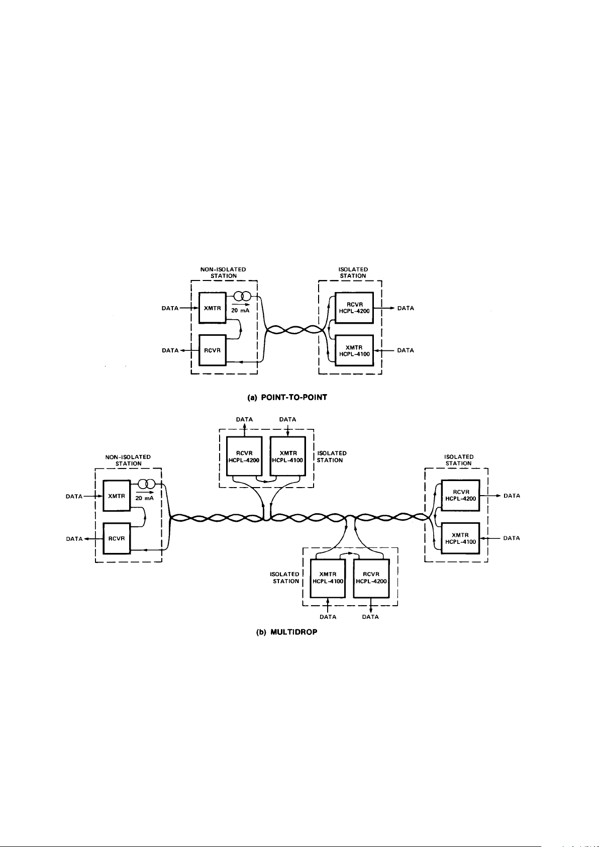
receivers shown in Figures 22a
and 22b. This configuration
allows the use of two wires to
carry data back and forth
between local and remote units.
However, protocol must be used
to determine which specific
transmitter can operate at any
given time. Maximum data rate
for a half duplex system is limited
by the loop current charging
time. These considerations were
explained in the Simplex configuration section.
Figures 22a and 22b illustrate
half duplex application for the
combination of HCPL-4100/-4200
optocouplers. The unique and
complementary designs of the
HCPL-4100 transmitter and
HCPL-4200 receiver
optocouplers provide many
designed-in benefits. For
example, total optical isolation at
one end of the current loop is
easily accomplished, which
results in substantial removal of
common mode influences,
elimination of ground potential
Figure 19. Minimum Required Supply
Voltage, VCC, vs. Loop Length for
Current Loop Circuit of Figure 19.
Figure 20. Typical Data Rate vs.
Distance.
TA = 25 °C
Figure 21. Full Duplex Point-to-Point Current Loop System
Configuration.
Page 12
1-384
differences and reduction of
power supply requirements. With
this combination of HCPL-4100/
-4200 optocouplers, specific
current loop noise immunity is
provided, i.e., minimum SPACE
state current noise immunity is 1
mA, MARK state noise immunity
is 8 mA.
Voltage compliance of the current
source must be of an adequate
level for operating all units in the
loop while not exceeding 27 V dc,
the maximum breakdown voltage
for the HCPL-4100. Note that the
HCPL-4100 transmitter will allow
loop current to conduct when
input VCC power is off. Consult
the HCPL-4100 transmitter
optocoupler data sheet for
specified device performance.
For more information about the
HCPL-4100/-4200 optocouplers,
consult Application Note 1018.
Figure 22. Half Duplex Current Loop System Configurations for
(a) Point-to-Point, (b) Multidrop.
 Loading...