

Page 1
Operating Instructions
QVGA Evaluation Kit
320x240LCD
HCK-A-1,V1.2
Page 2
OperatingInstructions
320x240LCD
10080BubbRd.Cupertino,CA95014408-252-1100Fax:408-252-1123www.hantronix.com
Page2
I.Description
II.KitInventory
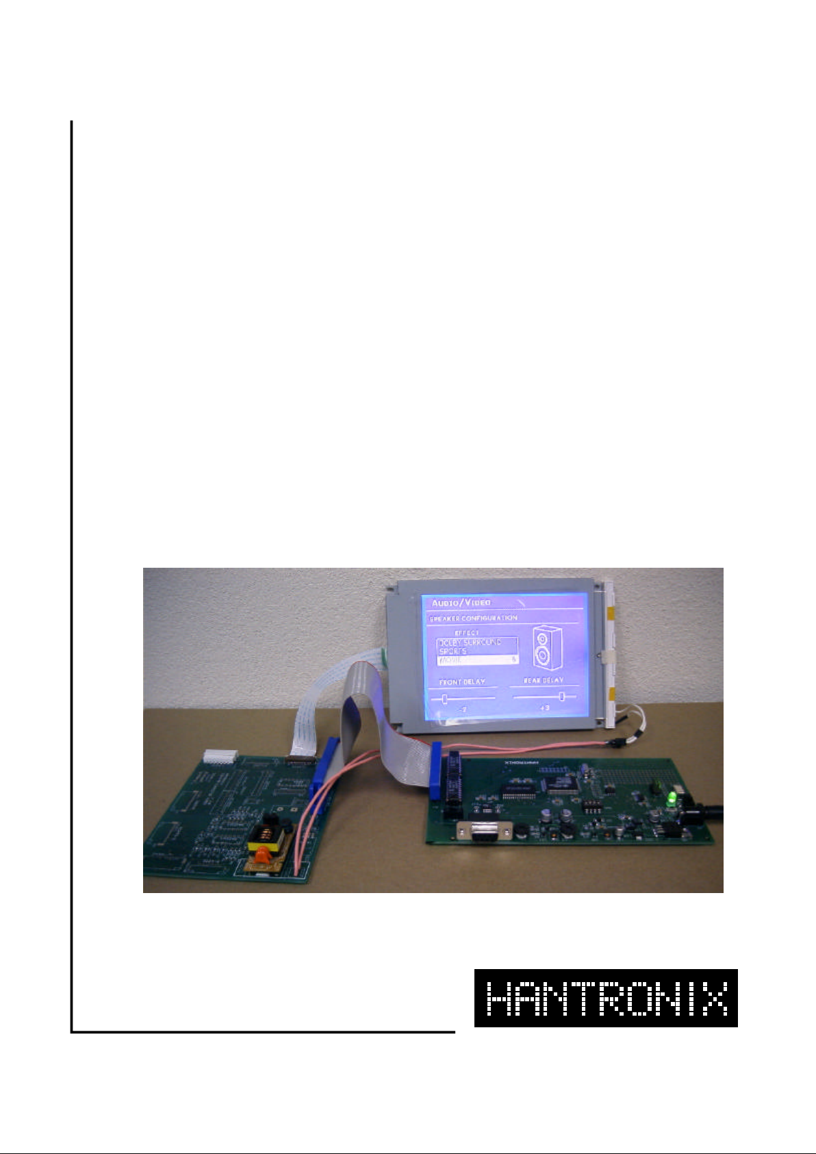
Thisevaluationkitisintendedtoprovidea
meansofevaluatingthequalityandsuitability
ofHantronixLCDdisplays.Itallowstheuserto
simplyandeasilyexercisetheLCDdisplay.
Thebasicdemoscreenisstoredinon-board
NVRAM.Implementationisprettysimple.Just
connectcablesamong3differentmodules,
controllerboard,connectorboardandLCD
module,andturnonpower.NoPCisrequired
toevaluateordemonstrateLCDmodules.
EasyGraphicUserInterfacingdevelopment
platformenablesrapidprototyping.Demo
contentscanbeeasilydesignedwithoff-theshelfwebeditors. Amuletcompilerconverts
thosetoanddownloadstothe
controllerboardthroughserialport.
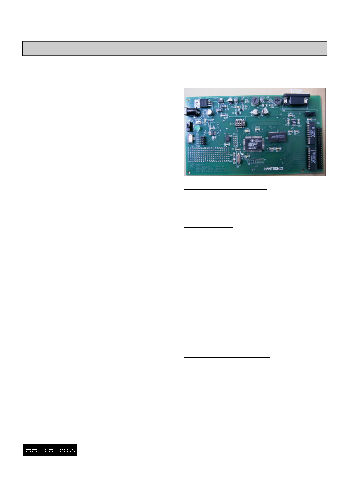
EasyGUIcontrollercard
40conductorflatribboncable.6”long.
Thisinstructionmanual.
AmuletµHTMLcompileranddocumentCD-
30daysevaluationcopy(Version2.1.9)
9pinserialcable
,6’long
ACAdaptor
?
?
?
?
?
?
µHTML
Thisisusefulfordevelopingthevarious
graphicandtextscreenthataretobeusedin
thefinalproductandforuseinsimulatingthe
appearanceandoftheproductfortradeshows
orevaluationbymarketingexperts.
forprogrammingtheEasy
GUIFLASH
III.ControllerBoard
LCDContrastAdjustKnob
Thereare2variableresistorstoadjustLCD
contrastvoltage.
VR1fornegativeLCdrivingvoltagerangefrom
-24vto-15v,
SW1PowerON/OFFSwitch
Sw3LCDPanelVoltage
NOTE:
GreenLED(D4)indicateswhetherpoweris
appliedornot.ACadaptorInput(J9)andReset
buttonarelocatednearby.
OFF(program)
OFF(115200)orON(19200)
Thismustmatchthebitrateset
forthecompiler.
OFF(disable)orON(enable)
ON(normal)orOFF(calibration)
efaultis5v.
SW2DIPSwitch
Switch1ON---BootMode
ON(normal)or
Switch2OFF--ProgramBaudRate
Switch3OFF--RAMTest
Switch4ON---TouchPanelMode
Itmustbesetfortheproperpanelvoltage,
either5vor3.3v.D
andVr2forpositiveLCdriving
voltagerangefrom14vto32v.
Page 3

OperatingInstructions
320x240LCD
10080BubbRd.Cupertino,CA95014408-252-1100Fax:408-252-1123www.hantronix.com
Page3
LCDConnectorBoardInterface(J11)
TouchPanelInterface(J10)
40-pinRibboncableisused.ItisasamePIN
configurationwithHCK-EEvaluationKit.
DB9connectortodownloadContentsfrom
Computer.
Resistiveanalog4-pinTouchpanelsare
supported.EitherJ4orJ5isusedtointerface
withadifferenttypeoftouchpanels.2x4pin
header(J10)isusedtoconnectX+,X-,Y+and
Y-signals.
J10J5J4
Y-1211
Y+3424
X-5632
X+7843
SerialConnector(J8)
Pin#SignalDescription
Pin#SignalDescription
2DOUTDatafromControllerBoard
1,3,5,7,9,11,D0~D7DataBus
11,13,15
2,8,14,20,26GNDGround
30-VlNeg.LCDbias
32Vdd5or3.3bySW3
33CP,CL2DataShift
34+12V
35DISPOFFH=On,L=Off
36+VlPos.LCDBias
37LP,CL1DataLatch
39FRMFirstLineMaker
40MACsignalforLC
3DINDatatoControllerBoard
5GNDSignalGround
4,6Jumpered
7,8Jumpered
PrototypingArea
20x70.1”throughholesareprovidedfor
additionallogicorconnector.
HantronixQVGAconnectorboardistoprovide
theinterfacebetweencontrolboardsfor
andandHantronixQVGAmodules.
ItprovidesinverterforCCFL(HVI-6)orEL
(HVI-5P)backlight.
TheavailablemodulesareHDM3224-1,
HDM3224-2,HDM3224-5,HDM3224-6,
HDM3224-7,HDM3224-C,andHDM3224C-S.
APPENDIX.HantronixConnectorBoard
HCK-
AHCK-E
Note:
Thisboardcanbesuppliedwiththe
availableHantronixLCDmodule.
 Loading...