

Page 1
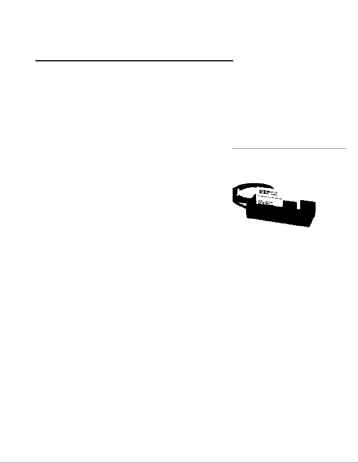
Industrial Digital Bar Code Slot
Reader
Technical Data
H
HBCS-7100 Series
Features
• Multi Resolution
Compatible with virtually all bar
code resolutions
• Large Slot Width
Allows reading thickly
laminated cards
• Sealed Metal Case (IP 66/67)
Can be installed outdoors or in
wet environments
• Tamper Proof Design
Ideal for security applications
• Minimal First Bar Distortion
• 880 nm Light
• Wide Operating Temperature
Range
-40°C to +70°C
• Wide Scan Speed Range
• Black Textured Epoxy Finish
• Digital Output
Open collector output compatible with TTL and CMOS logic
• Single +5 Volt Supply
Description
Hewlett-Packard’s Industrial
Digital Slot Reader is designed to
provide excellent scanning
performance on a wide variety of
bar coded cards and badges. It
contains a unique optical/
electrical system that integrates
over a large vertical area of the
bar/space pattern, providing a
greatly improved first read rate
even on poorly printed bar codes.
The HBCS-7100 Series uses an
infrared (880 nm) light with 0.19
mm (0.0075 in.) resolution.
The extra large depth of field
allows the slot reader to have a
slot width of 3.2 mm (0.125 in.),
thus making it possible to read
even thickly laminated cards and
badges. When used as a stand
alone optics module, the
maximum depth of field is
dependent upon resolution.
The optics and electronics are
housed in a rugged metal case.
The case is fully gasketed and
sealed, making it suitable for use
in outdoor or wet environments.
The black epoxy coating adds a
durable, finished look to the
Digital Slot Reader. When
installed using the rear screw
holes, the units become tamper
proof, making an excellent choice
for security access control.
The optical system is centered in
the slot track, allowing the user to
easily scan from either direction.
The wide slot width makes it easy
to insert and slide the cards. The
optical system is covered with a
recessed window to prevent
contamination and reduce the
wear on the cards.
The standard slot reader comes
with the optics module mounted
on a base plate with an opposite
rail and 122 cm (48 in.) straight
cord. Two standard connectors
are available: a male 5 pin, 240°,
locking DIN (HBCS-7100); or a
female, 9 pin D-sub squeeze to
release, (HBCS-7108).
The optics module (HBCS-7150)
is available which can be
integrated into other equipment
or used as a stand alone sensor
assembly.
Applications
The digital bar code slot reader is
a highly effective alternative to
5965-3007E
4-75
Page 2
keyboard data entry. Bar code
OPERATING DISTANCE – mm (INCHES)
0.05
(0.002)
8.0
(0.32)
MINIMUM SYMBOL RESOLUTION – mm (INCHES)
0.35
(0.014)
7.0
(0.23)
6.0
(0.24)
4.0
(0.16)
1.0
(0.04)
0.15
(0.006)
0.25
(0.010)
2.0
(0.08)
5.0
(0.20)
3.0
(0.12)
0.10
(0.004)
0.20
(0.008)
0.30
(0.012)
GUARANTEED
OPERATING
REGION
OPERATING
TYPICAL
REGION
scanning is faster and more
accurate than key entry and
provides far greater throughput.
In addition, bar code scanning
typically has a higher first read
rate and greater data accuracy
than optical character recognition. When compared to magnetic
stripe encoding, bar code offers
significant advantages in flexibility of media, symbol placement
and immunity to electromagnetic
fields.
Hewlett-Packard’s Industrial
Digital Slot Reader is designed for
applications where high first read
rate and durability are important
factors. The epoxy coated metal
case with its tamper proof
mounting system, makes these
slot readers ideal choices for
security access control, time and
attendance recording and other
bar coded badge and card reading
applications.
Electrical Operation
The HBCS-71XX family of digital
slot readers consists of a precision optical system, an analog
amplifier, a digitizing circuit, and
an output transistor. These
elements provide a TTL compatible output from a single 4.5 V to
5.5 V DC power supply. The open
collector transistor requires a
pull-up resistor for proper
operation.
A non-reflecting black bar results
in a logic high (1) level output,
while a reflecting white space will
cause a logic low (0) level output.
After power up, the slot reader
will be fully operational after
approximately 6 seconds. During
operation, the slot reader will
4-76
assume a logic low state after a
short period (typically 1 second)
if no bar code is scanned. This
feature allows multiple scanners
(slot readers and wands) to be
connected together with a simple
OR gate.
The slot reader connector provides a shield which is connected
to signal ground. The shield is
connected either to the metal
housing of the 5 pin DIN
connector, or to pin 8 of the 9 pin
D-sub connector. A good
connection to earth ground is
recommended.
The maximum recommended
cable length is 7.6 m (25 ft.).
WARNING:
OBSERVING THE INFRARED
LIGHT SOURCE IN THE HBCS7150 AT CLOSE DISTANCES
FOR PROLONGED PERIODS OF
TIME MAY CAUSE INJURY TO
THE EYE. When mounted with
the rail in place, the infrared
output flux is radiologically safe.
With the rail removed, precautions should be taken to avoid
prolonged visual observation.
Mounting Considerations
Slot Reader
The slot reader (HBCS-7100/
7108) is designed to be virtually
tamper proof when mounted
using the two rear mounting
holes. In this case, the cable must
be routed from the rear of the slot
reader through the mounting
surface (wall, door, etc.).
When mounting the slot reader,
the cable may be routed through
the mounting surface (see above),
or it may be routed along grooves
in the base and exit the side of the
slot reader at any of four points.
This allows flexibility in the
mounting orientation.
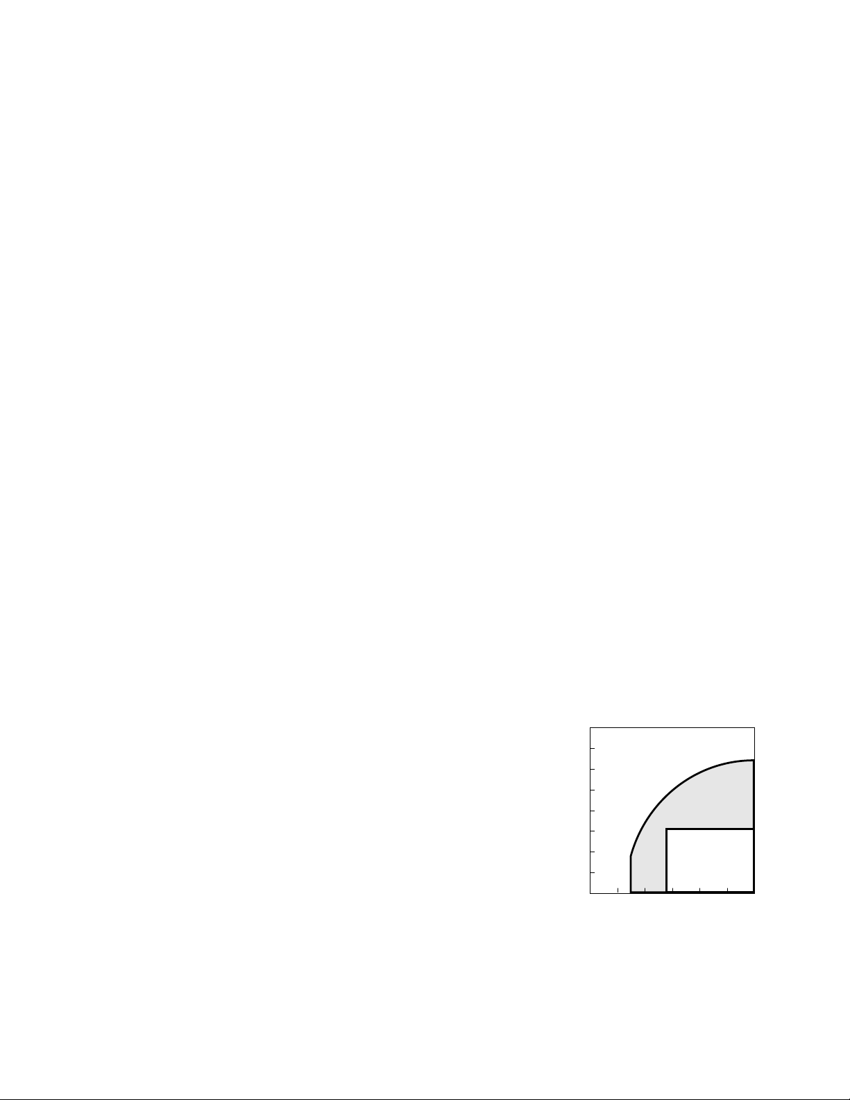
Optics Module
The optics/electronics module
(HBCS-7150) is designed for
applications which require a
different slot width, integration
into a larger housing, or a fixed
beam stationary scanner. When
using the optics module, the
operating distance from the front
surface of the module to the
symbol will vary depending on the
symbol resolution. Figure 1 shows
the relationship between operating range and minimum symbol
resolution for a typical optics
module.
This relationship was applied in
the design of the slot reader,
where a slot width of 3.2 mm
(0.125 in.) insures excellent
performance reading bar code
symbols which have a nominal
resolution of 0.19 mm (0.0075
in.) and include normal printing
errors.
Figure 1.
Page 3

Recommended Operating Conditions
Parameter Symbol Min. Max. Units Notes
Nominal Narrow Element Width 0.19 (0.0075) mm (in.)
Scan Velocity V
scan
Contrast RW-R
Supply Voltage V
Ambient Temperature T
Ambient Light E
S
A
V
B
20 (8) 254 (100) mm (in.) 1
45 % 2
4.5 5.5 V 3
-40 +70 °C4
100,000 lux 5
Absolute Maximum Ratings T
= 25°C (unless specified otherwise)
A
Parameter Symbol Min. Max. Units Notes
Storage Temperature T
Supply Voltage V
Output Transistor Power P
Output Collector Voltage V
S
S
T
O
-40 +80 °C
-0.3 +7.0 V
200 mW
-0.3 +20 V
Electrical Characteristics
TA = 25°C, VS = 4.5 V to 5.5 V (unless specified otherwise)
Parameter Symbol Typ. Max. Units Conditions Notes
Supply Current I
High Level Output Current I
Low Level Output Voltage V
Output Rise Time t
Output Fall Time t
S
OH
OL
r
f
Electrostatic Discharge Immunity ESD 25 kV 6
Notes:
1. Measured scanning a symbol with 0.19 mm narrow elements. For larger narrow element widths, the maximum scan speed will
increase proportionally.
2. Contrast is defined as RW-RB where RW is the reflectance of the white spaces and RB is the reflectance of the black bars, measured at
880 nm.
3. Allowable power supply ripple and noise is frequency dependent. See Figure 5.
4. Non-condensing. If there is frost or dew over the optics window, it should be removed for optimal scanning performance.
5. Direct sunlight at any illumination angle.
6. The shield must be properly terminated (See Figure 2). The human body is modeled by discharging a 300 pF capacitor through a
500 Ω resistor. No damage to the slot reader will occur at the specified level.
56 100 mA VS = 5.0 V
1.0 µAV
= 2.4 V
OH
0.4 V IOL = 16 mA
0.9 5.0 µs 10% - 90% transition
0.07 5.0 µs
RL = 1 kΩ
4-77
Page 4

Interface Specifications
1
2
3
4
5
V
The slot reader has two different
standard connectors: a 5 pin, 240
metal locking DIN; or a 9 pin
female D-sub squeeze to release.
The recommended interface is
shown in Figure 2. The mechani-
S
V
O
GND
SHIELD
10 kΩ 10 µF
cal specifications for the 5 pin
DIN are shown in Figure 3. The
mechanical specifications for the
9 pin D-sub are shown in
Figure 2. Recommended Interface.
Figure 4.
Pinout
5 pin 9 pin
Function DIN D-sub
V
S
Output 2 2
Ground 4 7
Shield Case 8
No Connect 3,5 1,3,4,5,6
Shield and ground are tied together in the connector.
Note: If the part is purchased with stripped and tinned wires, or if the connector is removed,
the ground and shield wires must be connected together for proper operation.
19
Figure 3. Connector Configuration for HBCS-71X0.
V
S
V
O
GND
Wire Color
PIN 9 PIN 5
9 PIN D-SUB FEMALE CONNECTOR
Function Color
V
S
Red
Output Yellow/White
Ground Black
Shield Braid
PIN 6 PIN 1
Figure 4. Connector Configuration for HBCS-71X8.
PSRR Performance
10000
1000
100
The CE Mark demonstrates
compliance with EC directives on
10
1
RIPPLE AMPLITUDE, PEAK-PEAK – mV
Figure 5. Ripple Noise Needed to Switch Output.
80 100 200 500 800 2000500080001000020000800001E+052E+055E+058E+
40
100
0
FREQUENCY – KHz
500
00
1E+
05
06
4-78
EMC.
96
Page 5

Dimensions
1.75
(0.69)
M5 x 0.80
TAPPED
HOLE
(2)
3.81
(1.50)
0.32
(0.125)
1.27 (0.50)
2.03 (0.80)
CABLE
12.70
(5.00)
1.75
(0.69)
2.79 (1.10)
CABLE
EXIT
CABLE
2.03 (0.80)
1.90 (0.75)
SLOT READER
(HBCS-7100/7108)
2.79
(1.10)
5.21
(2.05)
0.89
(0.35)
(0.65)
0.25 (0.10)
11.43
(4.50)
1.65
CABLE EXITS (2)
#8-32 TAPPED
HOLE (2)
0.475 (0.187) DIA.
LOCATING PIN (2)
2.03 (0.80) DIA.
MAX.
CABLE
1.65 (0.65)
11.43 (4.50)
12.70 (5.00)
OPTICS MODULE
(HBCS-7150)
Notes:
7. Mounting holes on the HBCS-7100/7108 are suitable for either #10-32 or M5-0.80 screws.
8. Mounting holes on the HBCS-7150 are for #8-32 screws.
9. Slot readers and optics modules have a black textured epoxy finish.
10. All dimensions are nominal and are stated in millimeters and (inches).
M5 x 0.80
(REF.)
1.90 (0.75)
1.27 (0.50)
3.81
(1.50)
Selection Guide
HBCS-7100 HBCS-7150
5 pin DIN Connector Standard Standard
9 pin D-Sub Connector HBCS-7108 NA
No Connector Strip HBCS-7104* HBCS-7154*
and Tin Leads
Individually Boxed Order Option #A01 with the above referenced part-number. The slot reader
Slot Reader is shipped in a “kraft” box, including an HBCS-7100 series data sheet.
*Build to order product only. Minimum stock available for engineering evaluation purchases.
4-79
Page 6

Symbol Placement
The center of the slot reader’s
optical system is located 12.7 mm
(0.50 in.) from the bottom of the
slot. Consequently, bar code
symbols to be read by the slot
reader must be positioned on the
card(s) or document(s) at a
height which insures that all bars
and spaces will cross a line located
12.7 mm from the bottom edge of
the card(s) or document(s). For
optimal performance, all bars and
spaces should cross the area
between 1.14 mm (0.45 in.) and
1.40 mm (0.55 in.) from the
bottom edge.
The bars and spaces should be
perpendicular to the bottom edge,
however, a skew of ± 4 degrees
from the perpendicular is
acceptable.
Maintenance Considerations
The slot reader and optics module
include a window which is slightly
recessed in order to prevent
direct contact with the bar code
symbol. This reduces the wear on
both the window and the symbol.
The window may become dirty
over a period of time. If this
occurs, clean the window with a
commercial glass cleaner.
Testing
All Hewlett-Packard slot readers
are 100% tested for performance
and digitizing accuracy after
manufacture. This insures a
consistent quality product. More
information about HewlettPackard’s test procedures, test set
up, and test limits are available on
request.
Optional Features
For options such as special cables
or connectors, contact your
nearest Hewlett-Packard sales
office or authorized
representative.
Warranty and Service
Hewlett Packard Slot Readers are
warranted for a period of one year
after purchase covering defects in
material and workmanship.
Hewlett-Packard will repair or, at
its option, replace products that
prove to be defective in material
or workmanship under proper use
during the warranty period.
NO OTHER WARRANTIES ARE
EXPRESSED OR IMPLIED,
INCLUDING BUT NOT LIMITED
TO THE IMPLIED WARRANTIES
OF MERCHANTABILITY AND
FITNESS FOR A PARTICULAR
PURPOSE. HEWLETT-PACKARD
IS NOT LIABLE FOR
CONSEQUENTIAL DAMAGES.
For additional warranty or service
information, please contact your
local Hewlett-Packard sales
representative or authorized
distributor.
4-80
 Loading...