

Page 1
Low Current Bar Code
Digitizer IC
Technical Data
H
HBCC-0500
Features
• Compatible with HP Bar
Code Sensors
– HBCC-1570 - 0.013 in.
0.33 mm
- HBCC-1580 - 0.007 in.
0.185 mm
- HBCC-1590 - 0.005 in.
0.13 mm
• Ambient Light Rejection
> 100 K Lux
• Accurate Digitizing of a
Wide Range of Bar Code
Labels
Description
The Hewlett-Packard Low Current
Bar Code Digitizer IC allows
designers to incorporate the high
ambient light rejection and low
power consumption features of
the HBCS-AXXX/TXXX wands
into their own bar code circuitry.
The HBCC-0500 is packaged in a
24 pin SOIC plastic package.
output of different sensor “bins”
is equalized by varying the
amplitude of the LED drive
current.
The sensor output has two components; DC due to ambient light,
and AC from the bar code label.
Photocurrent from the sensor is
amplified and high pass filtered
to remove the ambient light
signal. The AC component is
amplified and sent to an AM
detector to recover the bar code
information. The recovered bar
code signal is low pass filtered to
eliminate the 30 kHz carrier. The
signal is input to a digitizer
consisting of positive and negative
Block Diagram
SENSOR LED DRIVER
peak detectors and a comparator.
The comparator threshold is
generated from the peak
detectors using a resistor ladder.
This threshold, along with the
current bar code signal, is input
to a comparator. The output of
the comparator drives an external
output transistor.
Theory of Operation
The digitizer IC uses the techniques in US Patent 4,682,015 to
reduce power consumption and
sensitivity to ambient light.
Power is reduced by pulsing the
LED every 33 microseconds with
a 1 microsecond pulse. The
5964-1563E
AM
DETECTOR
AMPLIFIER
LOW PASS
FILTER
HIGH PASS
FILTER
DIGITIZER
AMPLIFIER
OUTPUT
4-33
Page 2
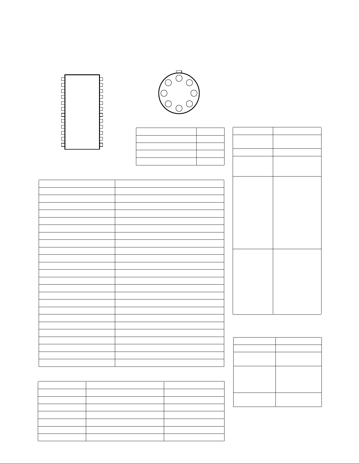
Pinout
RPER 1
RPWD 2
CTIM 3
V
CC
AGND 5
EMIN 6
PREO 7
A8
V
CC
PPKD 9
PRBP 10
PSTB 11
ACMP 12
4
HBCC-0500
24
LEDD
23
GND
22
LPFO
21
LPFI
20
IWSR
19
CMPO
18
CTHR
17
CMPI
16
NPKD
15
PSTI
14
CMPA
13
AMDT
Sensor Pinout
1 7
2 6
3 5
TOP VIEW
Function Pin #
LED Anode 6
LED Cathode 2
Detector Anode 8
Detector Cathode 1
Pin Description
Mnemonic Description
RPER Timer Period
RPWD Timer Pulse Width
CTIM Timer Capacitor
V
CC
Filtered Power
AGND Analog Ground
EMIN Preamp Emitter Input
PREO Preamp Output
VCCA Analog Power
PPKD Positive Peak Detector
PRBP Preamp Bias Point
PSTB Postamp Bypass
ACMP Compensation Cap
AMDT AM Detector
CMPA Compensation Cap
PSTI Postamp Input
NPKD Negative Peak Detector
CMPI Comparator Input
CTHR Comparator Threshold
CMPO Comparator Output
IWSR White State Return Current
LPFI Low Pass Filter Input
LPFO Low Pass Filter Output
GND Ground
LEDD LED Drive
Bin Table
Bin # 1570, 1580 Rb Ω 1590 Rb Ω
1 8.2 22
21127
31536
41847
52456
63075
73691
Sensor Marking
Sensors are marked with an eight
8
digit code, the last digit being the
“bin” number. The bin number is
used to determine the bin
resistor, Rb, using the Bin Table.
4
Parts List
Quantity Part
1 Sensor
1 HBCC-0500
1 1N4148
1 2N3904
1 2N4403
1 2N5088
2 39 Ω
1 9.1 kΩ
2 20 kΩ
2 56 kΩ
1 390 kΩ
2 470 kΩ
1 680 kΩ
1 1.3 MΩ
1 2.0 MΩ
2 6.8 MΩ
1 Bin resistor R
b
1 12 pF
1 75 pF
1 330 pF
1 680 pF
2 1.0 nF
1 2.2 nF
1 8.2 nF
4 0.1 µF
3 0.22 µF
1 0.47 µF
Optional Parts List
Quantity Part
1 1N4148
1 2N5088
1 2N3904
2 10 kΩ
1 220 kΩ
1 1.0 MΩ
1 2.0 MΩ
1 3.3 nF
1 1.0 µF
4-34
Page 3

Recommended Schematic
Shown is the recommended
schematic for the HBCC-0500.
Here are some construction tips.
1. Place the sensor, 2N4403, bin
resistor, and the 0.47 µF cap
close to each other to minimize
loop area.
2. If the 0.47 µF cap is tantalum,
its ESR must be used in series
with Rb to determine the
correct value for Rb.
3. A 1.0 µF ceramic cap may be
used in place of the 0.47 µF
cap.
4. Place the 0.22 µF cap attached
to pins 4 and 23 close to the
IC.
5. Use a single point ground close
to pin 23.
Options
There are four options on the
recommended schematic.
1. Output pull up resistor
2. Inverted output
3. Black state return
4. Threshold adjust
Pull Up Resistor
The 10 kΩ pull up resistor on the
standard or inverted output
transistor is optional. If the
transistor is driving a cable, the
resistor should be on the far end
of the cable.
Schematic
2N4403
LED ANODE
LED CATHODE
DETECTOR
CATHODE
DETECTOR
ANODE
SENSOR
Rb Ω
6
2
1
8
0.47
µF
+5 V
+5 V
680 KΩ
39 Ω39 Ω
0.22µF0.22
8.2 nF
470 KΩ
9.1 KΩ
6.8 MΩ
µF
2N5088
75 pF
0.1 µF
24
LEDD
4
V
CC
23
GND
15
PSTI
7
PREO
6
EMIN
5
AGND
1
RPER
2
RPWD
3
CTIM
9
PPKD
1 nF 1 nF
HBCC-
0500
CTHR
18
1N4148
CMPO
CMPI
LPFO
AMDT
CMPA
ACMP
IWSR
V
PRBP
PSTB
NPKD
390 KΩ470 KΩ
LPFI
CC
19
17
22
13
21
14
12
20
8
A
10
11
16
2.0 MΩ
20 KΩ
680 pF
56 KΩ 56 KΩ
2.2 nF
330 pF
12 pF
NC
0.22 µF
0.1 µF
0.1 µF
0.1 µF
1.3 MΩ
+5 V
10 KΩ (OPTIONAL)
20 KΩ
2N3904
+5 V
10 KΩ
(OPTIONAL)
INVERTED OUTPUT
(OPTIONAL)
+5 V
3.3 nF
1.0 MΩ
220 KΩ
2N5088
2.0 MΩ
BLACK STATE RETURN
(OPTIONAL)
1.0 pF
1N4148
OUTPUT
INVERTED
OUTPUT
4-35
Page 4

Inverted Output
The standard output of the
HBCC-0500 is high when the
sensor is looking at black bars,
increase the values of the 1.0 µF
and the 3.3 nF caps. The ratio of
values should be no more than
300:1.
and low when the sensor is looking at white spaces. If inverted
output is needed, add the extra
circuitry in the inverted output
block. Make sure that the 10 kΩ
pull up resistor on the normal
output transistor is loaded.
Threshold Adjustment
The standard circuit uses a
threshold designed for most bar
codes. If the bar codes to be read
consistently have narrow bars
that are lighter than the wide
bars, then the 470 kΩ and the
Black State Return
The HBCC-0500 normally returns
390 kΩ resistors attached to pin
18 should be swapped.
to the white state 100 milliseconds after the last transition. The
extra circuitry forces the black
state after a time out period set
by the 1.0 µF cap. The normal
time out period is about 1.5 seconds. If a longer time is needed,
Warranty and Service
HP Digitizer ICs are warranted
for a period of one year after
purchase covering defects in
material and workmanship.
Hewlett-Packard will repair or, at
Recommended Operating Conditions
Parameter Min. Max. Units Notes
Scan Velocity 7.6 (3) 76 (30) cm/sec (in/sec) 1
Edge Contrast 40 % 2
V
CC
Ambient Temperature -20 +65 °C
Ambient Light 100,000 Lux
Notes:
1. Narrow element width = 0.19 mm (0.0075 in.).
2. Contrast is defined as Rw - Rb, where Rw is the reflectance of the spaces in Rb is the
reflectance of the bars, measured at the sensor wavelength (655 or 820 nm). 100%
reflectance is barium sulfate.
3. Power supply ripple and noise should be less than 100 mV peak to peak.
4.5 6.0 V 3
its option, replace products that
prove to be defective in material
or workmanship under proper
use during the warranty period.
NO OTHER WARRANTIES ARE
EXPRESSED OR IMPLIED,
INCLUDING BUT NOT LIMITED
TO THE IMPLIED WARRANTIES
OF MERCHANTABILITY AND
FITNESS FOR A PARTICULAR
PURPOSE. HEWLETT-PACKARD
IS NOT LIABLE FOR
CONSEQUENTIAL DAMAGES.
For additional warranty or service
information, please contact your
local Hewlett-Packard sales
representative or authorized
distributor.
Electrical Characteristics
Parameter Symbol Typical Max. Units Notes
Supply Current, IC and Sensor I
High Level Output Current I
Low Level Output Voltage V
Output Rise Time t
Output Fall Time t
Wake Up Time t
Notes:
4. Rise and fall time will be dependent upon the capacitance of the cable.
5. Wake up time is defined as the time from initial power turn on until the circuit is
digitizing bar codes within data sheet limits.
4-36
CC
OH
OL
r
f
w
2.7 4.0 mA
1.0 µA
0.4 V
4.5 20 µs4
0.3 20 µs4
50 200 ms 5
 Loading...