

Page 1
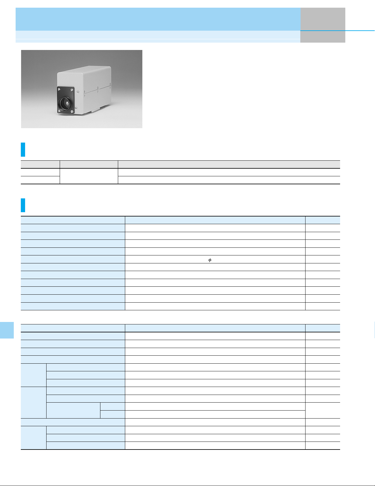
Gated PMT Modules
H7680/-01
The H7680/-01 PMT modules are capable of high-speed, high-repetition gated operation. An optimum design in the combination of circuit and photomultiplier tube delivers excellent gating characteristics including a minimum gate
width of 30 ns (H7680-01), 100 kHz repetition rate, and a gate extinction ratio
of 10
porating high-voltage power suppy circuit. And, the incorporated PMT gain
can be controled by adjusting the control voltage between +2 V to +5 V.
Product Variations
7
. The H7680/-01 can operate on a low +15 V supply because of incor-
Type No.
H7680
H7680-01
300 nm to 650 nm
Normally ON type
Normally OFF type
Specifications
Parameter
Supply Voltage
Max. Input Voltage
Max. Input Current
Max. Surge Current
Effective Area
Peak Sensitivity Wavelength
Pulse Linearity *
Max. Output Signal Current
Operating Ambient Temperature
Storage Temperature
Weight
Photocathode Material
Window Material
Dynode Structure
Number of Dynodes
Cathode
Characteristics
Anode
Character-
1
istics
*
1
Gain *
Time *1
Response
*1: Control voltage = +4.5 V
*2: Measured at the peak sensitivity wavelength
*3: Measured when photomultiplier tube operation is ON. After 30 minute storage in darkness
52
1
Parameter
Luminous Sensitivity
Radiant Sensitivity *
Blue Sensitivity Index (CS 5-58)
Luminous Sensitivity
Radiant Sensitivity *
Dark Current
Rise Time
Transit Time
TTS
2
2
Ty p.
3
*
Max.
H7680 / H7680-01
+14 to +16
+5 to +40
-20 to +50
H7680 / H7680-01
Bialkali
Borosilicate glass
Linear focused type
4.4 × 10
5 × 10
+17
400
4.0
24
420
100
100
850
10
95
88
11.0
475
10
200
1.7
16
500
FeaturesSpectral Response
Unit
V
V
mA
A
mm
nm
mA
µA
°C
°C
g
Unit
—
—
—
—
µA/lm
mA/W
—
A/lm
5
6
A/W
nA
—
ns
ns
ps
Page 2
PMT Module with Added Functions
Parameter
Mode
Gate Width (FWHM)
Rise Time, Fall Time
Gate Mode
Repetition Rate
Switching Ratio
Switching Noise
*4
Delay Time
Jitter
Gate Signal
Input
Gain Control
*4: Load resistance 50 Ω, peak to peak
Level
Input Impedance
Pulse Width
Input Voltage
Input Impedance
OFF time: 100 ns to
Max.
Max.
Max.
Max.
Max.
H7680 H7680-01
Normally ON
∞
Normally OFF
ON time: 30 ns to
20
100
7
10
60
200
1
C-MOS (High level: +3.5 V to +5 V)
50
100 ns to ∞
30 ns to ∞
+2.0 to +5.0
10
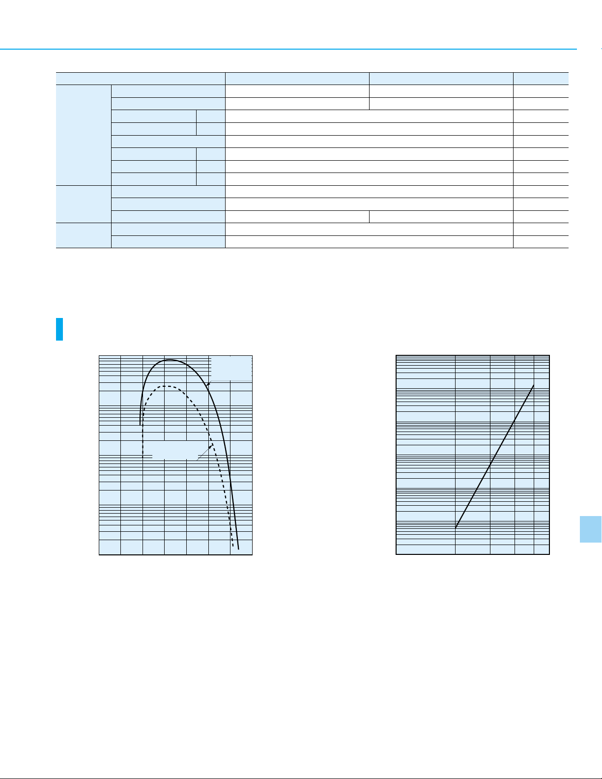
Characteristics (Cathode radiant sensitivity, Quantum efficiency, Gain)
TPMOB0148EA TPMOB0092EA
100
CATHODE
RADIANT
SENSITIVITY
8
10
7
10
∞
Unit
—
—
ns
kHz
—
mV
ns
ns
—
Ω
—
V
kΩ
10
QUANTUM
1
QUANTUM EFFICIENCY (%)
0.1
CATHODE RADIANT SENSITIVITY (mA/W)
0.01
200 400 600 800
EFFICIENCY
WAVELENGTH (nm)
6
10
5
10
GAIN
4
10
3
10
2
10
1234
CONTROL VOLTAGE (V)
6
5
53
Page 3

Gated PMT modules
Gate Timing Chart
H7680
(Normally ON Type)
+3.5 V to +5 V at 50 Ω
GATE SIGNAL INPUT
PMT OPERATION
0 V
OFF
ON
10 µs to
100 ns to
∞
∞
H7680-01
(Normally OFF Type)
GATE SIGNAL INPUT
PMT OPERATION
DELAY TIME : 200 ns MAX.
+3.5 V to +5 V at 50 Ω
OFF
DELAY TIME : 200 ns MAX.
0 V
ON
30 ns to
10 µs to
∞
MINIMUM GATE "OFF" TIME: 100 ns
∞
MINIMUM GATE "OFF" TIME: 30 ns
Gate time equals the pulse width of input gate signal.
Output Examples
H7680 H7680-01
TIME
0 V
OUTPUT
100 ns to ∞
90 %
50 %
10 %
0 V
OUTPUT
TPMOC0091EC
TIME
30 ns to ∞
10 %
50 %
90 %
10 ns
Block Diagram
SIGNAL OUTPUT: OUTPUT CURRENT (BNC)
PMT
GATE DRIVE
CIRCUIT
GATE POWER
SUPPLY CIRCUIT
POWER SUPPLY CIRCUIT
INPUT VOLTAGE
54
VOLTAGE
DIVIDER
CIRCUIT
TIMING
CIRCUIT
ERROR DETECTION
20 ns
HIGH VOLTAGE
POWER SUPPLY
CIRCUIT
CIRCUIT
GAIN
CONTROL
CIRCUIT
20 ns
TPMOB0094EC TPMOB0093EC
CONTROL VOLTAGE INPUT
GATE PULSE INPUT (BNC)
ERROR LED
ERROR MONITOR
OVER-LIGHT MONITOR
REF. VOLTAGE OUTPUT
TPMOC0090EB
10 ns
Page 4

PMT Modules with Added Functions H7680/-01
Sensitivity Adjustment Method
Voltage Programming Resistance Programming
H7680, -01
SIGNAL OUTPUT
*1: Not necessarily used.
*2: Do not use.
GATE SIGNAL INPUT (C-MOS)
BNC
6-pin
BNC
YELLOW
ERROR MONITOR
: *1
GRAY
OVER-LIGHT MONITOR
: *1
BLUE
Vref OUTPUT
: *2
WHITE
CONTROL
VOLTAGE
RED
BLACK
Dimensional Outline (Unit: mm)
POWER SUPPLY
+15 V
GND
+2 V to +5 V
GND
TPMOC0092EB
H7680, -01
*1: Not necessarily used.
GATE SIGNAL INPUT (C-MOS)
BNC
6-pin
BNC
SIGNAL OUTPUT
GRAY
OVER-LIGHT MONITOR
: *1
YELLOW
ERROR
MONITOR
: *1
BLUE
RED
WHITE
BLACK
POWER SUPPLY
+15 V
GND
POTENTIOMETER
MIN. +2 V
GAIN
CONTROL
10 kΩ
MAX. +5 V
TPMOC0093EC
PHOTOCATHODE ( 24)
20.0 ± 0.5
84.0 ± 0.55.0 ± 0.2
26.0 ± 0.2
58.0 ± 0.5
13.0 ± 0.2
170.0 ± 0.5
28.0 ± 0.2
50.0 ± 0.2
1"-32UN (C-MOUNT)
16.0 ± 0.5
50.0 ± 0.273.0 ± .05
SIDE VIEW
98.0 ± 0.5
25.0 ± 0.2
20.0 ± 0.220.0 ± 0.2
29.0 ± 0.5
4-M3 DEPTH: 51/4"-20 UNC DEPTH: 5
20.0 ± 0.220.0 ± 0.2
BOTTOM VIEW
Power cable with connector (HIROSE HR10A-7P-6S) is supplied with H7680/-01.
450 ± 20
13.0 ± 0.2
DC/CONT GATE
26.0 ± 0.2
74.0 ± 0.2
ERROR LED
RED
: LOW VOLTAGE INPUT (+15 V)
WHITE
: Vcontrol INPUT (+2 V to +5 V)
BLUE
: Vref INPUT
GRAY
: OVER-LIGHT MONITOR
YELLOW
: ERROR MONITOR
BLACK
: GND
POWER/CONTROL (6-PIN)
1: GND
2: LOW VOLTAGE INPUT (+15 V)
ERROR
3: Vcontrol INPUT
4: Vref OUTPUT
5: ERROR MONITOR
6: OVER-LIGHT MONITOR
SIGNAL OUT
GATE SIGNAL INPUT
(BNC-R)
SIGNAL OUTPUT (BNC-R)
REAR VIEWFRONT VIEW
TPMOA0002ED
55
 Loading...