

Page 1
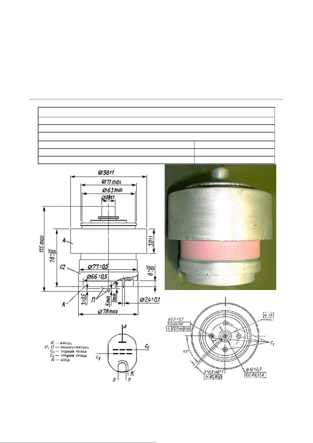
GU-84b
Tetrode
The GU-84B tetrode is used for power amplification in traveling-wave and single-sideband
signal amplifier circuits and as power amplifiers in RF equipment up to 250MHz.
GENERAL
Cathode: indirectly heated, oxide-coated.
Envelope: metal ceramic.
Cooling: forced air - 96 m3 / hr ( just under 57 CFM) at 30mm H2O for 1600W dissipation
Height, mm, at most: 115
Diameter, mm, at most: 99
Mass, Kg, at most: 1.5
Page 2
ENVIRONMENTAL OPERATING CONDITIONS
Vibration loads:
frequency, Hz 1-80
acceleration, m/s² 50
Multiple impacts with acceleration, m/s²
150
Ambient Conditions:
Temperature, °C -10 to +55
Relative humidity at up to +35 °C, % 98
NOMINAL ELECTRICAL PARAMETERS
Heater voltage, V 27.0
Heater current, A 3.7
Mutual conductance (Va = 750V, Vg2 = 375V, Ia = 2A, change in Vg1 = 1V), mA/V:
71
Negative bias (Vg1) with Va = 750V, Vg2 = 375V, Ia > 2A, V:
10-50
Negative cutoff bias (Vg1) with Va = 2KV, Vg2 = 375V, Ia = 20mA, V:
150
input capacitance, pF 102.5
output capacitance, at most, pF 20.5
transfer capacitance, pF <0.2
Warm up time, s: <180
AB1 Output, Va = 2KV, Vg2 = 375V, Ig1 < 0mA, Ig2 > 80mA, frequency 0.1-1 MHz, KW:
>1.5
Designed Tube Life (hours) >1500
ELECTRICAL PARAMETER LIMITS
Heater voltage, V 25.6-28.4
Heater current, A
3.4-4.0
input capacitance, pF 90-115
output capacitance, pF 18-23
Maximum CW Anode voltage (Va), KV:
2.2
"Maximum" Control Grid voltage (Vg1), V
-150
Maximum Screen Grid voltage (Vg2), V
400
CW cathode current (Ic), A:
2
Peak cathode current (Ic), A:
6
Anode Dissipation, W: 2500
Screen Grid (G2) Dissipation, W: 30
Control Grid (G1) Dissipation, W: 1
Temperature at envelope (hottest point), °C 200
Frequency, MHz: <250
Page 3
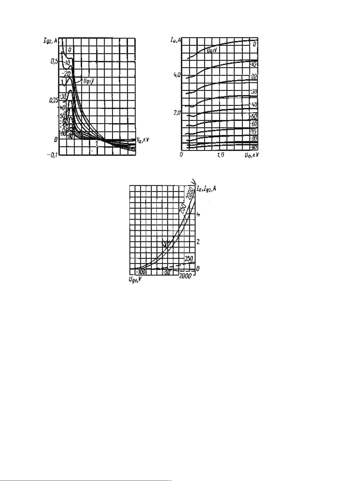
Averaged Grid-Anode Characteristic Curves:
Uf = 27V; Ug2 = 400V
Averaged Anode Characteristic Curves:
Uf = 27V; Ug2 = 400V
Averaged Anode-Grid and Grid Characteristic Curves:
Uf = 27 V; Ug2 = 400 V;
_____ Ia;
- - - I
g2
 Loading...