

Page 1
Dot Graphic VFD Module GU128x8T-K612C5
r
p
y
A
q 128 x 8 High Brightness Dot Graphic Displa
q Single 12V DC Supply
q Large 5x7 ASCII & European Font
q RS232 Asynchronous Serial Interface
q 31 Selectable Multi Drop Addresses
q Transformerless PSU (patent pending)
q Low Profile Construction
The module includes the VFD glass, VF drivers and microcontrolle
with refresh RAM, character generation, interface logic and
patented transformerless DC/DC converter. The RS232 serial
interface accepts 9600 or 19200 baud rates with optional parity bit.
The module features a low profile design with numerous custom
options available including special fonts and commands. Modules
can be connected to a multi dro
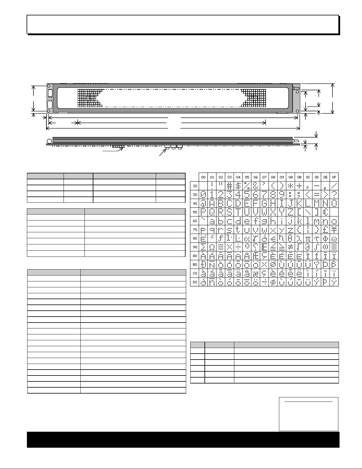
39.0
3.5
28.025
363.0
306.95
370.0
PL4 Pin 1
Body height 3.9mm max + Plunger height 1.1mm
ELECTRICAL SPECIFICATION
Parameter Symbol Value Condition
Supply Voltage VDD 12.0VDC +/- 10% GND=0V
Supply Current IDD 500 mA typ. VDD=12V
RS232 Input VsIL / VsIH -24V max / +24V max VDD=12V
RS232 Output VsOL/VsOH -5VDC min / +5VDC min VDD=12V
OPTICAL & ENVIRONMENTAL SPECIFICATION
Parameter Value
Display Area (X xYmm) 306.95 x 25.35
Dot Size/Pitch (XxY mm) 2.15 x 2.95 / 2.4 x 3.2
Luminance 1000 cd/m² Typ.
Colour of Illumination Blue-Green (505nm)
Operating Temperature
Storage Temperature
Operating Humidity
-40°C to +85°C
-40°C to +85°C
20 to 85% RH @ 25°C
Optical filters can provide violet, red, yellow, blue & green output.
SOFTWARE COMMANDS
Hex Command
10 Software Reset to power on state
11 Write Mode toggles overwrite / scroll
12 Write Direction toggles increment / decrement
13 Display On/Off. Data is retained
14 Display Invert. Toggle negative image
15 + xx Absolute Column Set from 00H – FFH
16 + xx Relative Column Set by 00H - FFH
17 + len + data Graphic Data Write 1 bytes per column, D7 top
18 Clear Character Buffer with 21 ASCII spaces
19 + data Write to Character Buffer for display effect
1A + effect Fade, wipe, scroll, dissolve & character delay.
1C + macro + len + data Store Macro E0H – FFH in EEPROM
1D + delay Delay – pause for up to 3 seconds
1E + 1E + 1E + FE Clear Macros from EEPROM
1E + 1E + 1E + FF Stop Display and clear receive buffer
1E + 1E + 1E + adr Address Select 00H – 1FH for active module
1F Loop receive buffer
20 - DF Character Write ASCII font.
E0 - FF Run Macro – execute user defined macro
60 + dh + dl Send Hexadecimal code instead of binary
The user can send non printable command codes 10H-1FH as hexadecimal by
prefixing the code using character 60H. Example: `15`3F = Position column 64.
When 1FH is sent, the commands/data in the communication buffer (max 192 bytes)
are executed until ‘Stop Display’ is issued. Example: 10H --- data --- 1FH.
Macro E0 is run at power on unless cleared.
Software and font set are copyright Noritake Itron Corporation 2002
address system.
28.5 46.025.35
6.825
3.5
1.6 10.7
Dimensions in mm & subject to tolerances. Mounting holes 3.5mm dia.
CHAR ACTER SET - 5X7 Font
Character 60H is used as a hexadecimal prefix, but can be displayed with a
repeat send. Column position X = 00H – 7FH.
Data is shown in hexadecimal and sent in binary. e.g. FFH = 11111111 Bin
ddress ‘adr’ = 00H - 1FH. Setting ‘adr’ to 00H activates all modules.
The communication settings and address can be set using the three switches on
the rear of the module. Default communication is Addr 00 - 9600,n,8,1 STD.
Choose between ‘STD’ (standard) and ‘WEB’ modes. In ‘WEB’ mode 20H and
all codes below 10H are ignored. To send a SPACE, 5FH can be used. All codes
are accepted when sent using hexadecimal. Select ‘WEB’ mode when using the
display with the Noritake Message Creator software.
PL4
Pin Signal Description
1 VDD 12V Supply
2 RXD RS232 received data
3 GND 0V supply
4 TXD RS232 transmitted data
5 DTR Module Busy if -5V
6 CTS Host Busy if -5V
Handshaking lines DTR/CTS should be linked if not used. Received data is
retransmitted from the module TXD output.
Detailed specification, software
commands and interface timing
are available on request.
Subject to change without notice.
IUK Doc. No. 03897 Iss.6
31 Mar 03
CONTACT
Noritake Sales Office Tel Nos
Nagoya Japan: +81 (0)52-561-9867
Canada: +1-416-291-2946
Chicago USA: +1-847-439-9020
Munchen (D): +49 (0)89-3214-290
Itron UK: +44 (0)1493 601144
Rest Europe: +49 (0)61-0520-9220
www.noritake -itron.com
NORITAKE ITRON VFD MODULES GU128x8T-K612C5
Page 2
Dot Graphic VFD Module GU128x8T-K612C5
y
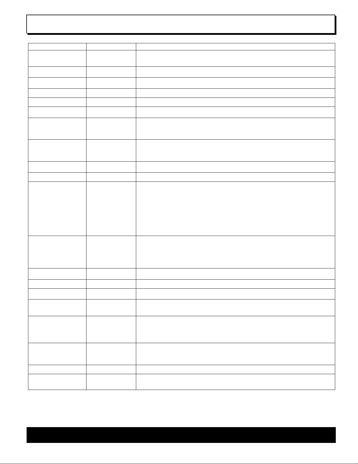
SOFTWARE COMMANDS AND CHARACTER CONTROL CODES
Instruction Hex Description
Software Reset
BUSY time = 500uS
Write Mode
BUSY time = 300uS
Write Direction
BUSY time = 300uS
Display On/Off
BUSY time = 300uS
Display Invert
BUSY time = 300uS
Absolute Column Set
BUSY time = 300uS
Relative Column Set
BUSY time = 300uS
Graphic Data Write
BUSY time = 300uS
Character Buffer Clear
BUSY time = 300uS
Character Buffer Write
BUSY time = 300uS
Display Effect
For BUSY times see individual effect
descriptions
Macro Store
BUSY times: macro number = 10ms
data byte = 5ms
last data byte = 20ms
Delay
BUSY time = 300uS
Macro Clear
BUSY time = 200ms
Stop Display
BUSY time = 300uS
Address Select
BUSY time = 300uS
Loop Receive Buffer
BUSY time = 300uS
Character Write
BUSY time = 300uS
Macro Run
BUSY time = 300uS
Send Hex Byte
BUSY times :-
st
and 2nd bytes = 300uS
1
rd
byte = respective command / data busy
3
Notes: When storing Macros definitions, the display may flicker. When erasing Macros, the display will momentarily go blank.
To send 60H in binar
10H Resets the VFD module. The display’s contents are cleared and the column position is set to
00H. The write mode is set to normal, the write direction is set to increment, the display is
turned on, and the display invert is turned off.
11H Toggles the write mode from normal write [default] to scroll write, and from scroll write to
normal write.
12H Toggles the writing direction from increment (left-to-right) to decrement (right-to-left), and from
decrement to increment. The default direction is increment.
13H Toggles the display from On [default] to Off, and from Off to On.
14H Inverts all data on the display.
15H + xx Sets the column position from 00H [default] to FFH. All written data is ignored if the column
position is set to 80H-FFH.
16H + xx Moves the current column position by xx amount. The column can be advanced by up to 127
pixels. The column positioning is constrained to a 128 pixel window, this allows the cursor to be
moved backwards as well as forward, e.g. 16H + 7EH - moves the column position back by
two.
17H + len + data Writes graphical data to the display from the current column position. If the write mode is set to
scroll, the whole display is shifted one column to the left or right (dependant upon the current
write direction). The graphical data length must be sent prior to the actual data. All graphical
data should be in a vertical orientation, with bit 7 uppermost.
18H Clears the internal 21-character buffer. This buffer is used in conjunction with the ‘Display
Effect’ commands.
19H + data Write 21-characters to the internal buffer.
1AH + effect Produce a display effect: -
00H – Fade display from ‘Off’ to maximum brightness.
01H – Fade display from maximum brightness to ‘Off’.
02H – Wipe display with the character buffer from left-to-right.
03H – Wipe display with the character buffer from right-to-left.
04H – Wipe display with the character buffer edge-to-center.
05H – Wipe display with the character buffer center-to-edge.
06H – Scroll display with the character buffer.
07H – Dissolve the display with the character buffer.
10H – 17H Set character delay (10H = No delay [default], 17H = Maximum delay)
1CH+macro+len+data Store a macro from E0H - FFH into non-volatile EEPROM. The first Macro (E0H), is always
executed at power up. The Macro data length must be sent prior to the data itself. Up to 256
command/data bytes can be assigned to each macro, and 1900 bytes are available for all
Macro definitions. All commands can be used in the Macros with the exception of ‘Address
Select’, ‘Macro Store’, ‘Macro Clear’ and ‘Macro Stop’. Please note that no provision is made
for protecting previously defined Macros.
1DH + delay Halts current processing for up to 3 seconds. Delay can be any value (00H - FFH)
55H = 1 second, AAH = 2 seconds, FFH = 3 seconds. (A value of 00H has no effect.)
1EH+1EH+1EH+FEH Clears all previously defined Macros.
1EH+1EH+1EH+FFH This command stops any running Macro. All display commands will be ignored if any Macro is
running. This command also stops ‘Loop Receive Buffer’ mode and clears the receive buffer.
1EH+1EH+1EH + adr Activate a display with address ‘adr’. All displays have can have a defined address of 00H-1FH.
If the display module’s address is not the same, all data will be ignored with the exception of
any new ‘Address Select’ commands. To activate all modules, set ‘adr’ to 00H.
1FH Activates a mode in which all commands/data present in the receive buffer up to the 1FH byte
itself is executed. When the 1FH is reached, execution begins again from the start of the buffer.
Sending the ‘Stop Display’ command ends this mode. The ‘Stop Display’ command should also
be sent prior to sending any commands/data to be used with this mode to ensure that the
receive buffer is empty.
20H - DFH Writes data direct to the display. The character write position is automatically advanced to the
right or the left, depending upon the selected write direction. If the write mode is set to scroll,
the display will scroll on the character from the left or right end. In ‘WEB’ mode, 20H is ignored
so to display a SPACE character send 5FH or `20.
E0H - FFH Execute the user defined Macro, E0H = Macro 1, FFH = Macro 32.
60H + dhH + dlH Write to the display module using a 2-byte hexadecimal number. dhH = high nibble, dlH = low
nibble. E.g. Sending `10 will reset the display.
form, the host must send 60H twice, otherwise the module will interpret it as a hexadecimal prefix.
NORITAKE ITRON VFD MODULES GU128x8T-K612C5
Page 3

Dot Graphic VFD Module GU128x8T-K612C5
A
r
INTERFACING TO THE GU128x8T-K612C5
ll communication to the VFD module is by the asynchronous serial interface. The factory default baud rate is set to 9600 with no parity. These settings can be changed
with the 3 push switches on the back of the module and are retained in EEPROM. All received data is re-transmitted from the module TXD output.
HOST
SYSTEM
I/O
I/O
I/O
I/O
VDDGND
RXD
TXD
GU128x8T-K612C5
CTS
DTR
VDD GND
HOST TO MODULE
RXD
START
BIT
DTR
MODULE TO HOST
TXD
CTS
Fig1: Waveforms show RS232 asynchronous serial.
>2us
START
BIT
<10us tBUSY
STOP BIT
STOP BIT
tBUSY is dependant on command / data sent.
COMMUNICATION SETTINGS
To change the communication settings, use the three push button switches on the rear of the module. First press the ‘STORE’ button to show the
current settings, then on each ‘UP’ / ‘DOWN’ key press, the settings will change, and the user can fix the selected settings by pressing the ‘STORE’
button. The parity bit is changed first, ‘N’ indicates no parity and ‘E’ indicates even parity. The baud rate will next change, ‘19200’ baud or ‘9600’
baud. The next setting to change is the module ‘Mode’. This can be ‘STD’ (standard) or ‘WEB’ mode. See details below. The last setting is the
display address, this can be changed to one of 32 addresses. The display address is shown in hexadecimal.
BAUD RATE = 9600, NO PARITY, DISPLAY ADDRESS = 1, WEB mode
STOREUP DOW N
MODULE MODE (STANDARD or WEB)
The module can operate in one of two main modes, STD (standard) or WEB. In STD mode all data received are displayed / processed as normal. In
WEB mode, the SPACE character (20H) and all codes below 10H are ignored. In this case the SPACE character can be displayed by one of two
methods:- either use hexadecimal (`20) or send character 5FH which is blank. The display must be in WEB mode when communication with the
display is from a PC via the ‘Generic / Text only’ Windows
TM
printer driver (as used with Noritake Itron Message Creator web software).
DISPLAY ORGANISATION
The display is organized as 128 vertical bytes (00H-7FH). Each character takes up 6 columns. All graphic data is written vertically, with the most
significant bit uppermost.
COLUMN 00H COLUMN 7FH
COLUMN POSITIONSMSB
DISPLAYING TEXT
Text can be sent direct to the display module. The column position is automatically advanced after each character is written. Using the ‘Absolute
Column Set’ command (15H), the user can perform more accurate text positioning, allowing text to be placed on any of the 128 columns. Text is
written from left to right, but can be reversed using the ‘Write Direction’ command.
TEXT POSITION DISPLAY TEXT
15H 16H “NORITAKE ITRON”
SCROLLING TEXT
Character data can be scrolled onto the display from either the left or right edge. To scroll on a single screens worth of text, use the ‘Characte
Buffer Write’ command (19H) to download the text into the display module. Then use the ‘Display Effect’ command (1AH) to scroll on the text. The
scroll direction can be set with the ‘Write Direction’ command (12H).
BUFFER WRITE
TEXT (21 characters) SCROLL BUFFER
19H “ NORITAKE ITRON ” 1AH 06H
Scroll Left
Using the ‘Write Mode’ command, the user can scroll longer text messages. Each character written to the display will scroll on from either the right
or left side (depending upon the ‘Write Direction’).
NORITAKE ITRON VFD MODULES GU128x8T-K612C5
Page 4

Dot Graphic VFD Module GU128x8T-K612C5
f
DISPLAY EFFECTS
The display provides a number of simple commands to enable a variety of effects to be achieved. Most of these work in conjunction with the internal
21 character buffer where the text is first written to the buffer followed by the required display effect (see the scrolling text example above).
Fade display up ( 1AH, 00H )
Increases the brightness of the display from OFF to maximum. The time taken for this operation is approx 0.5 sec.
Fade display down ( 1AH, 01H )
Decreases the brightness of the display from maximum to OFF. The time taken for this operation is approx 0.5 sec.
Wipe display with character buffer left to right ( 1AH, 02H )
Replaces the current contents of the display with the contents of the 21
character buffer one column at a time from the left to the right. The time
taken for this operation is approx 0.8 sec.
Wipe display with character buffer right to left ( 1AH, 03H )
Replaces the current contents of the display with the contents of the 21
character buffer one column at a time from the right to the left. The time
taken for this operation is approx 0.8 sec.
Wipe display with character buffer edge to center ( 1AH, 04H )
Replaces the current contents of the display with the contents of the 21
character buffer on a column by column basis starting from the edges and
ending in the center of the display. This can also be referred to as a ‘curtain
close’ effect. The time taken for this operation is approx 0.8 sec.
Buffer contents
Buffer contents
Buffer contents
Old screen contents (stays static)
Old screen contents (stays static)
Old screen contents (stays static)
Wipe display with character buffer center to edge ( 1AH, 05H )
Replaces the current contents of the display with the contents of the 21
character buffer on a column by column basis starting from the center and
ending at the ends of the display. This can also be referred to as a ‘curtain
open’ effect. The time taken for this operation is approx 0.8 sec.
Scroll display with character buffer ( 1AH, 06H )
Scrolls the contents of the 21 character buffer onto the display. The existing
contents of the display are scrolled off. The default scroll direction is right to
left but this can be toggled between right and left by issuing the ‘Write
Direction’ command. The time taken for this operation is approx 0.8 sec.
Buffer contents
Scroll direction can be changed to left to right using the Write Direction command
Old screen contents (scrolls off)
Old screen contents (stays static)
Buffer contents (scrolls on)
Dissolve display with character buffer ( 1AH, 07H )
Replaces the current contents of the display with the contents of the 21 character buffer by changing just 1 pixel at a time. The position of the pixels
changed is pseudo random and the visual effect is a dissolve from the old message to the new. The time taken for this operation is approx 0.8 sec.
Character delay ( 1AH, 10H – 17H )
Defines the length of delay after a character is written in normal write mode. The possible values are No delay (10H – [default]), 25ms (11H), 50ms
(12H), 100ms (13H), 150ms (14H), 200mS (15H), 250ms (16H) and 300ms (17H). With a character delay set, it is possible to send a string o
characters to the display at full speed but the string will be displayed a character at a time with the specified time delay between each character. This
frees up processing in the host by achieving the inter-character delay internally. Busy time = 300uS.
NORITAKE ITRON VFD MODULES GU128x8T-K612C5
Page 5

Dot Graphic VFD Module GU128x8T-K612C5
A
H
H
WRITING GRAPHICAL DATA
graphical image or icon can be placed in any column position. All graphical data should be in a vertical
format, with Bit 7 uppermost. The column position is advanced after each data byte.
MSB
BYTE 1
BYTE 9
RESET
GRAPHIC DATASET COLUMN POSITION
GRAPHIC IMAGE
10H 15H 3CH
17H 09H 00H 70H 11H DFH FCH DFH 11H 0CH 00H
GRAPHIC WRITE
GRAPHIC LENGTH
Graphical data can be scrolled onto the display by using the ‘Write Mode’
USING MACROS
Commands and data can be stored in internal EEPROM by using the macros. Macro contents are retained in the display module even after power
has been removed. There is provision for 32 macro’s, one of which (E0H) is treated as a special case in that it is run at power on. Each macro can
store up to 255 command / data bytes. There is a maximum of 1900 bytes available for all macros. Once a macro has been defined using the Macro
Store command, it can be run by sending the macro number (E0H – FFH). A running macro is stopped by sending the Stop Display command. To
make a macro repeat indefinitely, ensure that the last byte in the definition is the code of that macro. It is also possible to call a macro from within
another macro definition. Nesting can not however go any deeper that 1 level.
Macro example 1:- Define a macro to flash the message ‘ERROR’ in the center of the display indefinitely at 1Hz. This macro will run at power on.
DEFINE MACRO #1
MACRO LENGTH
500ms DELAY
1CH E0H 13H
15H 31H “ERROR” 1DH 2AH 15H 31H 20H 20H 20H 20H 20H 1DH 2AH E0H
SET COLUMN
TEXT SET COLUMN
TEXT START THIS MACRO AGAIN
Macro example 2:- Scrolling a message.
DEFINE MACRO #1 MACRO LENGTH
SCROLL TEXT
500ms DELAY
1CH E1H 1BH
10H 11H “WELCOME TO NORITAKE ITRON”
E1H
SCROLL MODE
START MACRO #1
Macro example 3:- Scrolling graphical data.
DEFINE MACRO #1 MACRO LENGTH
GRAPHIC DATA
1CH E1H 17
10H 11H 12H
SCROLL RIGHT
17H 12H 00H 0CH 12H 16H 29H 29H 46H 82H 82
82H 82H 86H 89H 89H 46H 22H 1CH 00H
E1H
GRAPHIC WRITE & LENGTH
START MACRO #1
MSB
Scroll Left
BYTE 1
Scroll Right
BYTE 18
NORITAKE ITRON VFD MODULES GU128x8T-K612C5
Page 6

Dot Graphic VFD Module GU128x8T-K612C5
A
LOOP RECEIVE BUFFER
The display has a 192 byte first in first out (FIFO) receive buffer. Commands / data that have been sent to the module can be processed again and
again using the ‘Loop Receive Buffer’ command. In order for this to work correctly, the buffer needs to be cleared first using the ‘Stop Display’
command. Then the required sequence of commands / data is sent. Finally the ‘Loop Receive Buffer’ command is sent. Sending ‘Stop Display’
again stops the sequence.
Loop example :- Flash the message ‘ERROR’ in the center of the display indefinitely at 1Hz. This has the same effect as Macro example 1 above.
STOP DISPLAY
1EH 1EH 1EH 1FH
500ms DELAY
15H 31H “ERROR” 1DH 2AH 15H 31H 20H 20H 20H 20H 20H 1DH 2AH 1FH
SET COLUMN
TEXT
SET COLUMN
TEXT LOOP RECEIVE BUFFER
500ms DELAY
MULTI DROP ADDRESSING
It is possible to connect up to 31 display modules to the same host. Each module can be set to have a unique address (see details in
‘Communication Settings’ section. Any module set to have address 00H will receive and process all data. In order for a module with an address
other than 00H to accept data, the host must first send an ‘Address Select’ command with ‘adr’ specifying the address of the module to send the
data to. If the ‘Address Select’ command is sent with ‘adr’ set to 00H, all modules process the data that follows irrelevant of their address.
Addressing example :- A system comprising 3 display modules connected to one host system.
Module 1 is set to ’01 - 9600N STD’.
Module 2 is set to ’02 - 9600N STD’.
Module 3 is set to ’03 - 9600N STD’.
To display ‘Call 0 for attention’ on module 1 : 1EH 1EH 1EH 01H 10H 15H 04H “Call 0 for attention”
To display ‘Welcome to Noritake!’ on module 2 : 1EH 1EH 1EH 02H 10H 15H 04H “Welcome to Noritake!”
To display ‘Stores/Goods In’ on module 3 : 1EH 1EH 1EH 03H 10H 15H 13H “Stores/Goods In”
Then to display ‘!! Evacuate !!’ on all modules : 1EH 1EH 1EH 00H 10H 15H 16H “!! Evacuate !!”
I/O
HOST
SYSTEM
TX
RX
I/O
ADDRESS SELECT
RXD
TXD
RXD
TXD
RESET & SET POSITION
Module 1
Module 2
TEXT
DTR
CTS
DTR
CTS
Module 3
RXD
TXD
DTR
CTS
Module connections :-
s all data received at a module’s RXD input is retransmitted from it’s TXD output, In the above example the modules are daisy chained together so
that the TXD output of one module is connected to the RXD input of the following one. In this example, handshaking is used so the DTR / CTS lines
are daisy chained in a similar fashion. The system can be simplified by not using the handshaking lines at all but care must be taken by the host not
to fill the display module(s) communication buffer in which case data can be lost. An even simpler solution would be to just use the TX output of the
host and connect this to all the module RXD lines. This solution enables each module to be connected using just 3 wires (VCC, RXD and GND). The
disadvantage of this (in addition to the lack of handshaking) is that the host RS232 driver must be capable of driving the number of displays (RXD
inputs) in the system.
NORITAKE ITRON VFD MODULES GU128x8T-K612C5
 Loading...