

Page 1
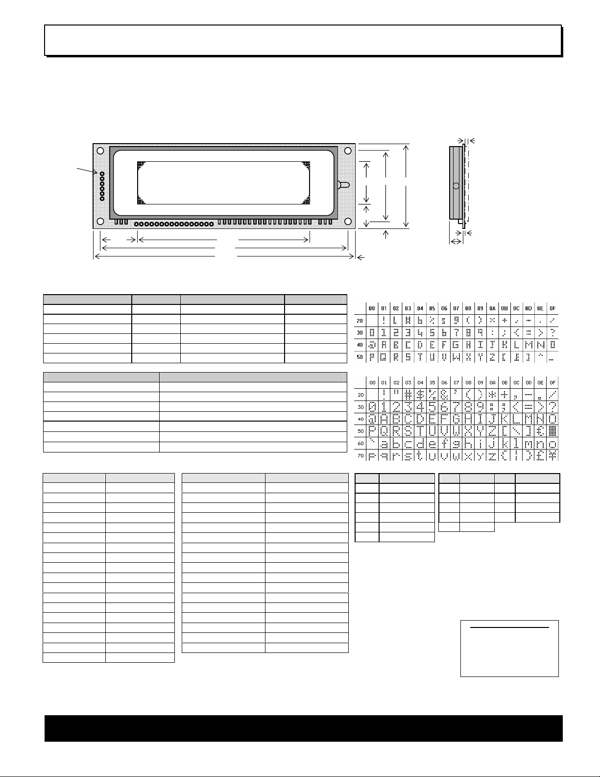
Dot Graphic VFD Module GU126x32F-K612A4
126 x 32 High Brightness Dot Graphic Display
Single 5V DC Supply
3 ASCII Fonts ( 5 x 5, 5 x 7, and 10 x 14 )
SPI & RS232 Asynchronous Serial Interface
8 User I/O Pins with Key Scanning Capability
Transformerless PSU (patent pending)
Low Profile Construction
CON1
The module includes the VFD glass, VF drivers and microcontroller with refresh RAM, character generation, interface logic
and patented transformerless DC/DC converter. The RS232 serial
interface is full duplex and accepts various baud rates up to 38,400.
The module features a low profile design with numerous custom
options available including special fonts and application specific
commands.
2.5
20.6
31.0
38.0
1
10.2
3.5
3.5
Dimensions in mm & subject to tolerances.
Mounting holes 3.5mm dia.
1.6
8.4
18.0
1
CON2
83.05
119.0
126.0
ELECTRICAL SPECIFICATION
Parameter Symbol Value Condition
Power Supply Voltage VDD 5.0VDC +/- 10% GND=0V
Power Supply Current IDD 400mA typ. VDD=5VDC
RS232 Input VsIL / VsIH -24V max / +24V max VDD=5VDC
RS232 Output VsOL / VsOH -5VDC min / +5VDC min VDD=5VDC
Logic Input VIL / VIH 0.8VDC max / 2.0VDC min VDD=5VDC
Logic Output VOL / VOH 0.5VDC max / 2.4VDC min IOH=-2.0mA
OPTICAL & ENVIRONMENTAL SPECIFICATION
Parameter Value
Display Area (X xYmm) 83.05 x 20.65
Dot Size/Pitch (XxY mm) 0.5 x 0.5 / 0.65 x 0.65
Luminance 600 cd/m² (200 fL) Typ.
Colour of Illumination Blue-Green (505nm)
Operating Temperature
Storage Temperature
Operating Humidity
Optical filters can provide violet, red, yellow, blue & green output.
SOFTWARE COMMANDS
Hex Command Hex Command
01-07 Run Macro 19 Reset
08 Backspace 1A + data Write Mode
09 Horizontal Tab 1B + macro+len+data Set Macro
0A Line Feed 1B + 4D Erase All Macros
0B Home 1B + 4C/55 Lock/Unlock EEPROM
0C Vertical Tab 1B + 43 Request Checksum
0D Carriage Return 1B + 50/46 Power On/Off
0E Clear End of Line 1B + 48/42 Hex Write On/Off
0F Test 1B + 49 + data Set Comms
10 + x + y Cursor Position 1B + 44 + data Enable I/O Port
11 +xl+yt+xr+yb Set Area 1B + 4F + data Set Port Lines
12 +xl+yt+xr+yb Clear Area 1B + 52 Read Port
13 +xl+yt+xr+yb Invert Area 1B + 4B Enable key scanning
14 +xl+yt+xr+yb Set Outline 1B + F8-FF Brightness
15 +xl+yt+xr+yb Clear Outline 1C / 1D / 1E Select Font
16 Set Pixel 1F +xl+yl+xr+yb+data Graphic Area Write*1
17 Clear Pixel 20 - 7F Character Write
18 + len + data Graphic Write
The module defaults to a 4 line of 21 character display using the 5x7 font with single
pixel spacing. The cursor position auto increments after each character write. The
bottom left of a character is placed at the cursor x,y. To send commands as
hexadecimal, prefix the 2 bytes using character 60H. Example: `10`3F`01 = Position dot
x=64 y=1. To send character 60H to the display, send 60H twice.
-40°C to +85°C
-40°C to +85°C
20 to 85% RH @ 25°C
*1
Applies to version 3 software only.
CHARACTER SETS
MINI FONT (PROPORTIONAL SPACING)
5x7 & 10x14 FONTS (FIXED SPACING)
CON1
Pin Signal
1 VDD
2 RXD
3 0V
4 TXD
5 MB
6 HB
The Module Busy line (MB) indicates the module is busy
when low. If handshaking is not required, connect the Host
Busy (HB) input to the Module Busy output.
Connect MISO and MOSI at power-up to enable the test
mode and restore factory defaults.
CON2
Pin Signal Pin Signal
1 /SS 6 MISO
2 0V 7 SCK
3 VDD 8 /IRQ
4 /RES 9-16 P0-P7
5 MOSI
CONTACT
Noritake Sales Office Tel No s
Nagoya Japan: +81 (0)52-561-9867
Canada: +1-416-2 91-2946
Chicago USA: + 1-847-439-9 020
Munchen (D): +49 (0)89-3214-290
Itron UK: +44 (0)1493 6 01144
Rest Europe: +49 (0)61-052 0-9220
www.noritake-itron.com
Subject to change without notice.
IUK Doc. No. 03926 Iss.4
13 Feb 06
NORITAKE ITRON VFD MODULES GU126x32F-K612A4
Page 2
Dot Graphic VFD Module GU126x32F-K612A4
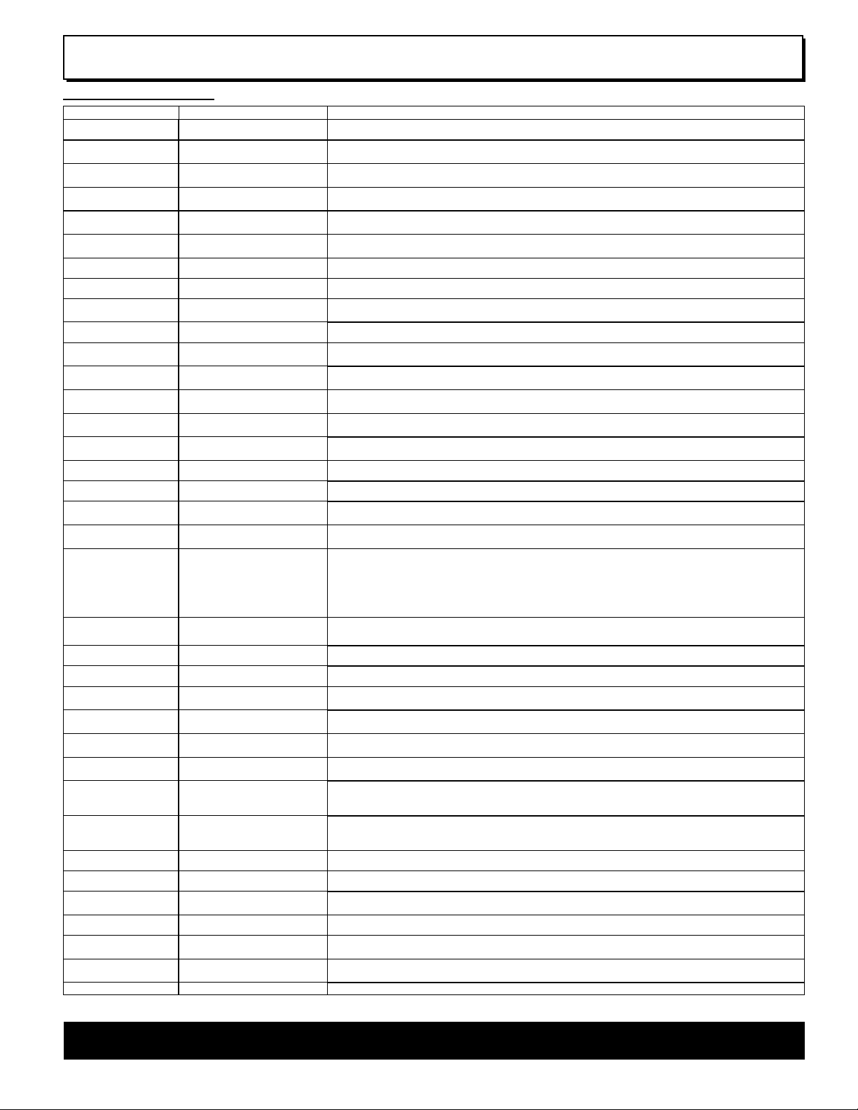
SOFTWARE COMMANDS
Instruction Data Format Description
Macro Start
(BUSY time depends on contents)
Backspace
(50µs)
Horizontal Tab
(50µs)
Line Feed
(50us)
Home
(50us)
Vertical Tab
(50us)
Carriage Return
(50us)
Clear EOL
(2.5ms)
Test
(50µs)
Cursor Position
(50us)
Set Area
(50us + 1ms [last byte])
Clear Area
(50us + 1ms [last byte])
Invert Area
(50us + 1ms [last byte])
Set Outline
(50us + 1ms [last byte])
Clear Outline
(50us + 1ms [last byte])
Set Pixel
(50us)
Clear Pixel
(50us)
Graphic Write
(50us + 250us [each data byte])
Reset
(500us)
Write Mode
(50us)
Set Macro
(50us [1BH], 10ms [macro], 50us
[len], 5ms [data], 20ms [last byte])
Brightness
(50us)
Erase Macros
(100ms)
Lock/Unlock EEPROM
(50us + 5ms [last byte])
Checksum
(50us)
Power On/Off
(50us)
Hex/Binary Mode
(50us)
Set Comms
(50us + 5ms[last byte])
Enable I/O Port
(50us + 5ms[last byte])
Set Port Lines
(50us)
Read Port
(50us)
Enable Key Scanning
(50us + 5ms[last byte])
Select Font
(50us)
Graphic Area Write
(50us + 250us [each data byte])
Hex Prefix
(50µs + 50us command BUSY)
Character Write (400us) 20H - 7FH Display character from selected font.
Notes: - Busy times are not inclusive of a 50us scan period, this must be taken into consideration. If the cursor is enabled, busy times will increase by a further 50us.
All coordinates are absolute. The origin (00H, 00H) is the top left of the display. All data shown is in hexadecimal format.
01H - 07H Start user defined macro 1-7.
08H Non destructive backspace. Cursor is moved left by the width of the currently select font. If the cursor is at
the left end of the display, no cursor movement is made.
09H Cursor is moved right by the width of the currently select font. If the cursor is at the end of the display, no
cursor movement is made.
0AH Moves the cursor down by the height of the currently selected font. If the cursor is at the bottom of the
display, no cursor movement is made.
0BH Moves the cursor horizontal position to 00H, the vertical positioning is dependent on the currently selected
font, allowing for immediate character writing in the top-left corner of the display.
0CH Moves the cursor up one character row. If the cursor is at the top of the top end of the display, no cursor
movement is made.
0DH Moves the cursor horizontal position to 00H. The vertical position is unchanged.
0EH Clear all characters from the current cursor position to the end of the display.
0FH Place module into self-test mode. The module will repetitively show a few test screens. The test mode will
exist on the next received byte.
10H + xpos + ypos Set the cursor position.
11H + xleft + ytop + xright + ybot Fill specified area. All dots within the specified area are illuminated. Please note that the cursor position is
affected with this command.
12H + xleft + ytop + xright + ybot Clear specified area. All dots within the specified area are cleared. Please note that the cursor position is
affected with this command.
13H + xleft + ytop + xright + ybot Invert specified area. All dots within the specified area are inverted. Please note that the cursor position is
affected with this command.
14H + xleft + ytop + xright + ybot Draw box outline. All dots within the specified outline are unchanged. Please note that the cursor position is
affected with this command.
15H + xleft + ytop + xright + ybot Clear box outline. All dots within the specified outline are unchanged. Please note that the cursor position is
affected with this command.
16H Illuminate a single pixel at the current cursor position.
17H Clear a single pixel at the current cursor position.
18H + len + data Write graphical data, length len, direct to display. See write mode command (1AH) for graphic orientation
and cursor movements.
19H Resets display to power-on defaults: - Display is cleared. 5x7 font selected. Write Mode = 00H
Brightness Level = 7. VFD Power = On.
1AH + data Bit 7 = graphic data orientation - 0 = horizontal, 1 = vertical (default = horizontal)
Bit 6 = cursor movement - 0 = horizontal, 1 = vertical (default = horizontal)
Bit 5 = cursor direction - 0 = forward, 1 = backwards (default = forwards)
Bit 4 = underscore cursor - 0 = off, 1 = on (default = off)
Bit 3 = underscore cursor - 0 = static, 1 = flash (default = static)
Bit 1/0 = pen type - 00 = overwrite, 01 = AND, 02 = OR, 03 = XOR (default = overwrite)
1BH + macro + len + data Send macro data to EEPROM. macro = 00H - 07H. Macro0 is executed at power-up only. A maximum of 480
bytes is allowed for macro data. The display may flicker whilst writing macro data.
1BH + level Set the display brightness. level = F8H - FFH. F8H = display off. F9H = minimum, FFH = maximum (default).
1BH + 4DH Clear all downloaded macros in EEPROM. Screen may blank momentarily while macro data is being erased.
1BH + 4CH / 55H All data contained within the non-volatile EEPROM is locked (4CH), and no changes are possible until the
unlock command (55H) is executed.
1BH + 43H All data received is added to the checksum. This command will read the lower 8-bits of that checksum,
before being cleared. Please note that the checksum is cleared when executing the test mode.
1BH + 50H / 46H 50H = Turn on VFD power supply (default).
46H = Turn off VFD power supply, display’s contents will be preserved.
1BH + 48H / 42H 48H = Enable hex receive mode, character 60H is interpreted as a hexadecimal prefix.
42H = Disable hex receive mode. Hex mode is enabled at power up.
1BH + 49H + data Set asynchronous communication baud rate and parity. Takes effect at power-up or hardware reset.
Bit 7 = Automatic I/O send (0=off, 1=on). Bits 1&0 = baud rate (00=4800, 01=9600, 02=19200, 03=38400).
Bit 2 = Parity (1=even, 0=none) (factory default = 19200 with no parity, automatic I/O send is off)
1BH + 44H + data Set I/O port direction. A ‘1’ indicates an input, a ‘0’ an output. All output lines are immediately set low. All
input lines have their pull-ups enabled. This value is store in EEPROM and will automatically be set at power
up.
1BH + 4FH + data Set Output lines on I/O port, a ‘1’ will set 5V on the output ports, or enable the pull-ups on the inputs.
1BH + 52H Read current I/O port status. A single byte is transmitted showing the current state of the I/O lines.
1BH + 4BH Set I/O port to key scanning. The I/O ports are continuously scanned for any key press. This mode is stored
in EEPROM and will automatically be selected at power up.
1CH / 1DH / 1EH Select font. 1CH = proportional mini font. 1DH= fixed spaced 5x7 font. 1EH = fixed spaced 10x14 font.
1FH + xl + yt + xr + yb + data Write graphic data within defined area. See write mode command (1AH) for graphic orientation and cursor
movements. Note: This command is available on software version 3 only.
60H + dhH + dlH Write to the display module using a 2-byte hexadecimal number. dhH = high nibble, dlH = low nibble.
E.g. Sending `19 will reset the display.
NORITAKE ITRON VFD MODULES GU126x32F-K612A4
Page 3

/IRQP0
g
Dot Graphic VFD Module GU126x32F-K612A4
INTERFACING TO THE GU126x32F-K612
All control communication to the VFD module is by the RS232 asynchronous or TTL synchronous serial interfaces. The asynchronous
communication speed and parity can be changed with the ‘UART SETUP’ command. These settings are stored in EEPROM and become active at
power up or hardware reset. The factory default settings are 19200 baud, with no parity.
ASYNCHRONOUS SERIAL COMMUNICATION
HOST
SYSTEM
TXD
RXD
I/O
I/O
I/O
RXD
TXD
GU126x32F-K612A4
HB
MB
/RES
The host must provide adequate delays for the module to process the command and data. These ‘busy’ times
are specified in the software command section. To change from the default communication settings, use the
VDD GND VDD GND
HOST TO MODULE
RXD
START
BIT
MB
MODULE TO HOST
TXD
HB
Fig1: Waveforms show RS232 asynchronous serial.
>2us
START
BIT
<20us tBUSY
STOP BIT
STOP BIT
UART SETUP COMMAND
1BH 49H 05H
‘UART SETUP’ command. Any changes of the communications settings are stored in non-volatile EEPROM and
become effective at power up. The example on the right shows how to change the baud rate and parity.
SYNCHRONOUS SERIAL COMMUNICATION
HOST
SYSTEM
I/O
I/O
I/O
I/O
I/O
MOSI
MISO
GU126x32F-K612A4
SCK
/SS
/RES
VDD GND VDD GND
When using synchronous communications. Data is clocked in on the rising
ed
e of SCK. The most significant bit of the data byte should be sent first.
/SS
>125ns
SCK
MOSI
MISO
Fig2: Waveforms show TTL synchronous serial.
Min 250ns
>250ns >250ns
MSB MSBLSB
MSB MSBLSB
Min 20ns
BUSY
9600, EVEN PARITY
The synchronous serial interface is active and able to receive data when /SS is held low. The /SS line is useful for packet / byte synchronization to
keep the internal bit counter logic synchronous with the host. When /SS is driven high the send and receive logic is reset and any partially received
data is discarded. The host must provide adequate delays for the module to process the data. These data/command busy times are specified in the
software command section.
RESET TIMING
/RES
DATA
I/O CONTROL
>50ns
The module is reset when a low-level signal is applied to the /RES line. This will cause the
30ms
module to clear the display, initialise the UART setting and set all power-up defaults. During this
initialisation period, the user must delay any transmission to the module.
The module contains simple Input and Output functions for the 8 I/O lines (P7-P0). All inputs include an
optional pull-up resistor, 30K-120K in value. The outputs can source ~5mA and sink ~30mA.
The following example sets up the I/O lines to control the 2 LED’s and provide a pull-up resistor for the switch.
ENABLE I/O MODE
1BH 44H 80H
P0/1 = OUT, P7 = IN
SET I/O LINES
1BH 4FH 80H
ENABLE P7 PULL-UP, TURN ON LED1&2
The status of P0-P7 can be transmitted when a change in level is detected on any pin. This automatic
response mode can be enabled by using the ‘UART SETUP’ command. When this mode is enabled, the VFD
module can reliably check port changes every 15ms. With auto send disabled (default) a manual read
command is required to determine the port status.
READ PORT
1BH 52H
SW1 CLOSED
RESPONSE
00H
SW1 OPEN
80H
When using synchronous serial communications, the host can detect a level change with the
/IRQ line on CON2. This allows the host to poll the port status only when needed.
-7
LED1 LED2
SW1
< 15ms
GU126x32F-
P0
P1
P7
I/O CONTROL
> 1us
VDD
K612A4
GND
NORITAKE ITRON VFD MODULES GU126x32F-K612A4
Page 4

Dot Graphic VFD Module GU126x32F-K612A4
DISPLAYING TEXT
The module contains 3 font sizes, a proportional mini-font, 5x7 pixel, and a 10x14 pixel font.
Characters of any size can be written to any part of the display. All data sent to the module from
20H to 7FH is treated as character data. Characters are positioned above the current cursor
position, see Fig1. Each character written will include a one pixel space on the right side of the
character. After each character is written to the display, the cursor position is automatically
advanced. If the cursor position reaches the end of the display, the host must reposition to the
next line.
The following example displays two text messages in the center of the display.
5x7 FONT DISPLAY TEXT SET CURSOR
1DH 10H 15H 0FH ‘NORITAKE ITRON’ 10H 1EH 17H ‘VFD MODULES’
The next example displays one line of text using the 10x14 font.
10x14 FONT DISPLAY TEXTSET CURSOR
DISPLAY TEXT SET CURSOR
0,0
0,7
Fig3: Cursor Positioning, example of writing 2
characters from cursor position 0,7.
Displaying text in the small 5x7 font.
6,7
1EH 10H 1EH 17H ‘126x32’
The module can display a cursor to aid character positioning and text input. The
size of the cursor depends upon the currently selected font, and can be set to flash
or remain static.
5x7 FONT DISPLAY TEXT ENABLE FLASHING CURSOR SET CURSOR
1DH 10H 04H 0AH ‘ENTER NAME: ’ 1AH 18H
DISPLAYING GRAPHICS
Graphical images can be displayed on the VFD module in either a horizontal or vertical byte orientation. After each graphical data write, the cursor
is automatically advanced, depending upon the direction selected in the ‘Write Mode’ command. The most significant bit is positioned to the top
(vertical data) or to the left (horizontal data).
The following example displays a simple graphical image using horizontal graphic data. The write mode
is first set to horizontal data format, with a vertical cursor movement. The cursor is positioned before
sending the 8 byte of graphical data using the graphics command.
SET HORIZONTAL WRITE MODE
GRAPHIC DATA GRAPHIC WRITE SET CURSOR LENGTH
1AH 40H 10H 28H 0CH 18H 08H 1CH 5CH 48H 3EH 1DH 1DH 14H 36H
The next example displays a simple graphical image using vertical graphical data. The write mode is
first set to vertical data format, with a horizontal cursor movement. The cursor is positioned, then the
top 20 bytes are sent using the graphic write command. The cursor is then repositioned to send the
bottom 20 graphical bytes.
Displaying text in the large 10x14 font.
Using the cursor to aid user input.
MSB
Fig4: Graphic Image using horizontal data
MSB
BYTE2
BYTE1 BYTE21
- 1CH
- 5CH
- 48H
- 3EH
- 1DH
- 1DH
- 14H
- 36H
BYTE19
BYTE20 BYTE40
SET VERTICAL WRITE MODE
GRAPHIC DATA GRAPHIC WRITE SET CURSOR LENGTH
1AH 80H 10H 50H 08H 18H 14H 00H 00H 00H 00H 07H 04H C7H FEH 72H 73H
32H 3EH 3FH 1DH 00H 00H 00H 00H 00H 00H
Fig5: Graphic Image using vertical data
10H 50H 10H 18H 14H 00H 3CH 42H 81H B9H C1H 42H 7CH 20H D8H
FCH 3CH FCH CAH 49H B1H 89H 42H 3CH 00H
The graphic area write command 1FH uses top-left and bottom-right XY co-ordinates to define an
area to which graphical data bytes will be written. The orientation is set-up using the write mode
command 1AH. Unused bits are masked where the screen area is not a byte multiple.
Displaying graphic images in vertical and horizontal format.
NORITAKE ITRON VFD MODULES GU126x32F-K612A4
Page 5

Dot Graphic VFD Module GU126x32F-K612A4
AREA COMMANDS
The VFD module contains commands to fill, clear and invert defined areas of the display. Also an outline command is available to draw rectangles
around objects.
The following example displays three options for the user to select, each option is contained within a box with a shadow effect. Drawing horizontal
and vertical line using the fill area command creates the shadow effect.
SET CURSOR DISPLAY OPTIONS
10H 05H 13H ‘SETUP’
10H 2FH 13H ‘PRINT’
10H 5EH 13H ‘RUN’
BOX OUTLINE
BOX OUTLINE
TOP LEFT
TOP LEFT
BOTTOM RIGHT
BOTTOM RIGHT
14H 00H 0AH 26H 14H
14H 2AH 0AH 50H 14H
14H 54H 0AH 7AH 14H
HORIZONTAL LINE SET AREA VERTICAL LINE FILL AREA
11H 01H 15H 27H 15H 11H 27H 0BH 27H 15H
11H 2BH 15H 51H 15H 11H 51H 0BH 51H 15H
11H 55H 15H 7BH 15H 11H 7BH 0BH 7BH 15H
The next example uses the invert area command to select one of the options.
INVERT AREA BOTTOM RIGHT
TOP LEFT
Display options with simple text write.
Boxes created using the ‘Set Outline’ comm and.
Drop Shadows created with the ‘Set Area’ comm and.
13H 55H 0BH 79H 13H
Option ‘Run’ selected with the ‘Invert Ar ea’ command.
WRITE MODES
By default, display data that is overwritten will be cleared prior to displaying any new data. This display data can be maintained whilst writing by
selecting the ‘OR’ mode with the ‘Write Mode’ command, this will effectively merge the old data with the new. The ‘AND’ write mode will only display
written data if existing data is present on the display. The other ‘Write Mode’ is ‘XOR’ which can be useful for writing text on an inverted display.
The following example uses the XOR mode to write text on a full display.
WRITE MODE XOR M ODE SET AREA TOP LEFT BOTTOM RIGHT
11H 00H 00H 7DH 1FH
1AH 03H 10H 18H 13H ‘INVERETED TEXT’
Displaying inverted text using the ‘Write Mode’ command.
This next example uses the XOR mode to display the percentage completed on
a progress bar.
WRITE MODE XOR M ODE
10H 26H 0DH ‘PROGRESS’
14H 00H 12H 7DH 1CH
11H 00H 12H 3CH 1CH
1AH 03H 10H 38H 1BH ‘50%’
Using inverting text for displaying progress level.
NORITAKE ITRON VFD MODULES GU126x32F-K612A4
Page 6

Dot Graphic VFD Module GU126x32F-K612A4
MACROS
A string of data and commands can be sent to the module and stored in non-volatile EEPROM by using the macro feature. This string of data and
commands can then be executed by using just one command. Up to 8 macros can be used at any one time, one of these is executed at power-up.
This example uses the first macro (Macro 0) to display an initial message at power-up.
WRITE TO MACRO-0 LENGTH
POWER-UP MESSAGE
1BH 00H 24H
10H 1EH 0DH ‘PLEASE WAIT’
10H 06H 19H ‘INITIALISING SYSTEM’
Power-Up message using Macro 0.
This next example saves the previous graphic icon into Macro 1, and then is used as a user-defined character.
WRITE TO MACRO-1 LENGTH
1BH 01H 0CH
1AH 40H 18H 08H 1CH 5CH
GRAPHIC DATA
48H 3EH 1DH 1DH 14H 36H
DISPLAY ICON DISPLAY ICON SET CURSOR SET CURSOR
10H 05H 05H 01H 10H 72H 04H 01H
10H 35H 0EH 01H 10H 46H 16H 01H
Using Macros as user-defined characters.
This example creates a display template, which can be helpful if many screens require the same look.
WRITE TO MACRO-2 LENGTH
1BH 02H 1BH
RESET
19H 14H 02H 02H 7BH 1DH 11H 00H 00H 04H 04H
AREA COMMANDS
11H 00H 1BH 04H 1FH 11H 79H 00H 7DH 04H
11H 79H 1BH 7DH 1FH
DISPLAY TEMPLATE SET CURSOR DISPLAY MESS AGE
02H 10H 1CH 13H ‘SYSTEM READY’
Using Macros as a screen template.
EEPROM PROTECTION
The EEPROM contains information such as macro data, asynchronous communication settings and I/O configuration. So it is important to protect
this information from stray commands due to communication failures. To protect the EEPROM, the module contains a ‘EEPROM Lock’ command
(1BH + 4CH). Once this command is issued, no further EEPROM updates can be made until it is unlocked (1BH + 55H).
USING THE CHECKSUM
All data written to the module is added to an internal checksum. The lower 8-bits of this checksum can be read at any time from the module by the
host system to confirm accurate data transfer. It is up to the user if or when this feature should be used. The checksum is cleared at power-up and
after each checksum read.
Example: Read checksum at power-up, or directly after it has been cleared.
READ CHECKSUM
SENT TO HOST
1BH 43H
CHECKSUM
5EH
Example: Read checksum after data has been written to the display.
WRITE DATA
19H 31H 32H 33H
READ CHECKSUM
1BH 43H
CHECKSUM
SENT TO HOST
0DH
NORITAKE ITRON VFD MODULES GU126x32F-K612A4
 Loading...