

Page 1

GS300T48-5
300W DC-DC CONVERTER
Type V
GS300T48-5 38 to 60 V 5,075 V 60 A
i
V
o
I
o
FEATURES
Veryhigh output power (300W)
High efficiency(80%min.)
Paralleloperation with current sharing
Synchronizationpin
Remote ON/OFF
Remote loadvoltage sensecompensation
Output short-circuit protection
Output overvoltageprotection
Thermal protection
Undervoltagelock-out
Minimalovershoot duringload transients
500 V
inputto output isolation
DC
Internal inputand output filtering
Softstart
PCB or chassismountable
DESCRIPTION
The GS300T48-5 is a 300W DC-DC converters
used to generate a 5.075V isolated output with a
current of 60A from a widerange input voltage(38
to 60V).
SELECTIONGUIDE
Type
Ordering Number
GS300T48-5
GS300T48-5E
June 1994 1/6
Input
Voltage (V)
38 to 60 5.075 60
Output
Voltage
(V)
Output
Current
(A)
Dimensions
L • W • H mm (inches)
125 • 66.5 • 20
( 4.92 • 2.62 • 0.79)
The suffix E identifies the metric threading
on the planar heatsink (see fig. 1).
Page 2
GS300T48-5
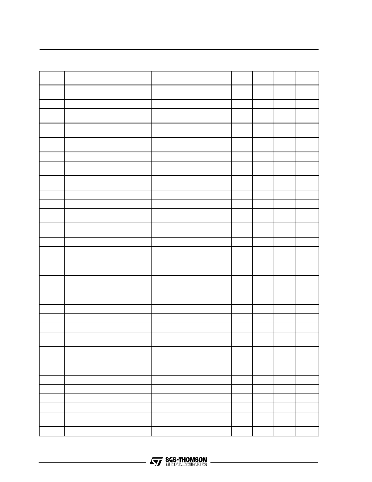
ELECTRICAL CHARACTERISTICS (T
Symbol
Input Voltage Vo= 5.075V Io= 0 to 30A
V
i
V
l
ipk
V
l
ien
V
V
V
V
V
V
V
∆V
δV
I
I
osc
t
V
R
T
cop
T
* Thermalintervention @ T
Input Undervoltage Lockout Io = 0 to 60A
iuv
AverageInput Current Vi= 48V
l
i
Inrush TransientPeak Current Vi= 60V
Reflected Input Current Vi= 48V Io= 60A
l
ir
Enable Input Voltage Vi= 38 to 60V Io= 0 to 60A
ien
Enable Input Current Vi= 38 to 60V Io= 0 to 60A
Max Inhibit Voltage Vi= 38 to 60V Io= 0 to 60A
iinh
Input Power Vi= 38 to 60V Io= 0A(No Load)
P
i
TotalOutput VoltageRegulation Vi= 38 to 60V Io= 0 to 60A
o
Short-term Output
ost
VoltageRegulation
TotalStatic Output
ots
VoltageRegulation
Output Overvoltage Limit Initiation Vi= 38 to 60V Io= 0 to 60A
ol
Output Ripple Voltage Vi= 38 to 60V Io= 60A
or
Output Noise Voltage Vi= 38 to 60V Io= 60A
on
TotalRemote Sense
o
Compensation
Peak Load Transient Response Vi= 48V δIo= 10A
o
Output Current Vi= 38 to 60V Vo=5V
I
o
OvercurrentLimit Initiation Vi= 48V
ol
Shortcircuit Output Current Vi= 48V
Load Transient Setting Time Vi= 48V δIo= 10A
t
s
Turn-onTime Vi= 38 to 60V Io= 0 to 60A
on
IsolationVoltage
is
Switching Frequency Vi= 38 to 60V Io= 0 to 60A
f
s
Efficiency Vi= 38 to 60V Io= 60A
η
Thermal Resistance Case toAmbient
th
Operating Case
TemperatureRange*
Storage TemperatureRange
stg
Parameter Test Conditions Min Typ Max Unit
=85°C
cop
=25°C unless otherwisespecified)
amb
(Operating Conditions)
Io= 60A
Io= 60A
BW = 5Hz to 20MHz (see fig. 2)
V
=0V
ien
Vien= open
Vi= 38 to 60V Io= 0 to 60A
Vi= 38 to 60V Io= 0 to 60A
BW = 0 to 20 Mhz
BW = 0 to 20 Mhz
Vi= 38 to 60V
slope = 0.1A/µs
slope = 0.1A/µs
V
= from high to low
ien
Vi= 0 to 60V Io= 0 to 60A
V
= low
ien
38 48 60 V
DC
29 36 V
7.8 A
2
0.3 A
s
30 mApp
0 1.2 V
–1 mA
818V
1.5 2 W
4.490 5.075 5.210 V
5.002 5.075 5.148 V
4.970 5.075 5.180 V
6.3 V
50 mVpp
100 mVpp
0.6 V
100 mVp
060A
63 A
69 A
250 µs
10 ms
10
500 V
160 180 200 kHz
80 81 %
5.2 °C/W
0 +70 °C
– 40 +105 °C
2/6
Page 3

CONNECTION DIAGRAM AND MECHANICAL DATA
Figure1.
GS300T48-5
PackageU. Dimensions in mm (inches)
PIN DESCRIPTION
Pin Function Description
1,2 - Vin
3,4 + Vin
5 SYNC
6 PARALLEL
7 ON/OFF
8 CASE
9 + SENSE
10 - SENSE
11,12,
13,14
15,16,
17
- OUT
+ OUT
Negativeinput voltage.
Positive input voltage. Unregulated input voltage (typically 48V) must beapplied between
pin 1,2-3,4.
Synchronization pin. See figures 3, 4, 5, 6. Open when not used.
Parallel output. See figures 3, 4, 5, 6. Open when not used.
The converteris ON (Enable) when the voltage applied to this pin with reference to pin 1,2
is lowerthan 1,2 V (see Vien).The converter is OFF (Inhibit) for a control voltage in the
rangeof 8 to18V.
When the pin is unconnected the converter is OFF (Inhibit).
Case connection pin
Senses the remote load high side.To be connected to pin 15,16,17 when remote sense is
notused.
Senses the remote load return. Tobe connected to pin 11,12,13,14 when remote senseis
notused. In parallel configuration, take care to connect all -SENSE pins together (see
figures 3,4,5,6).
-5Vvoltage return.
+5V output voltage.
3/6
Page 4

GS300T48-5
USER NOTES
Reflected Input Current
The reflectedinput current measurement (lir, see ElectricalCharacteristics)is performedaccording to the
test set-upof fig. 2.
Figure2.
Softstart
To avoid heavy inrush current the output voltage
risetimeis 10ms maximumin anyconditionofload.
Remote Sensing
The remote voltage sense compensation range is
for a totaldrop of 0.6Vequally shared betweenthe
load connectingwires.
It is a good practice to shieldthe sensingwires to
avoid oscillations.
See the connectiondiagramon figures 3, 4, 5, 6.
Remote ON/OFF
The module is controlled by the voltage applied
betweenthe ON/OFF pin and -IN pin.
The converter is ON (Enable) when the voltage
appliedis lower than 1.2 V (see Vien on Electrical
Characteristics).
The converteris OFF(Inhibit) for a control voltage
in the range of 8 to 18V (seeViinh).
4/6
When thepin is unconnectedthe converteris OFF.
Maximum sinkingcurrentis 1mA.
Module Protection
The module is protected against occasional and
permanent shortcircuits of the output pins to
ground, aswell asagainst outputcurrentoverload.
It uses a current limiting protection circuitry,avoiding latch-upproblems with certaintype of loads.
A latchingcrowbar output overvoltageprotection is
activated when the output voltage exceeds the
typical value of 6.3V (see Electrical Characteristics).Athermalnon-latchingprotectiondisables
the module whenever the heatsink temperature
reachesabout 85°C.
Parallel Operation
To increase available output regulated power, the
module features the parallel connection possibility
with equalcurrent sharingand maximum deviation
of 10% (two modules in parallel).
See the connectiondiagramon figures3, 4, 5, 6.
Page 5

Figure3. Figure 4.
GS300T48-5
Figure 5.
Thermal Characteristics
The case-to-ambient thermal resistance of the
GS300T48-5module is 5.2°C/W typical. It may be
decreased, improving the convection cooling, by
mountingan externalheatsink tothe top of the unit
heatsink(fig. 9).
Figure 6.
Six threadedholes, # 4-40UNC on the standard or
# M3onthe Eversion,5mm(0,2”) maximum deep,
are providedfor this purpose (see fig.1).
5/6
Page 6

GS300T48-5
Information furnished is believed to be accurate and reliable. However, SGS-THOMSON Microelectronics assumes no responsibility for the
consequences ofuse of such information nor for anyinfringement of patents or other rights of third parties which may result from its use. No
licenseis granted by implication or otherwise under any patent or patent rights of SGS-THOMSON Microelectronics. Specification mentioned
in this publication are subject to change without notice. This publication supersedes and replaces all information previously supplied.
SGS-THOMSON Microelectronics products are notauthorized foruse as critical components in life support devices or systemswithout express
written approval of SGS-THOMSON Microelectronics.
1994 SGS-THOMSON Microelectronics –All Rights Reserved
Australia - Brazil - China - France - Germany - Hong Kong - Italy - Japan - Korea - Malaysia - Malta -Morocco - TheNetherlands -
Singapore - Spain - Sweden - Switzerland - Taiwan- Thailand - United Kingdom - U.S.A.
SGS-THOMSON Microelectronics GROUP OF COMPANIES
6/6
 Loading...