

Page 1

NUMBER
GS-12-192
TYPE
PRODUCT SPECIFICATION
TITLE PAGE REVISION
GIG-ARRAY® High Speed Mezzanine Connectors
15-35 mm Board to Board
AUTHORIZED BY DATE
CLASSIFICATION
1.0 OBJECTIVE
This specification defines the performance, test, quality, and reliability requirements of the GIG-ARRAY
High Speed Mezzanine 1.00 x 0.65 mm BGA Differential Connector System. This specification applies for
Eutectic SnPb BGA as well as Lead Free SnAgCu BGA product that meets the requirements of the
European Union Directive of Restrictions for Hazardous Substances (Directive 2002/95/EC).
2.0 SCOPE
This specification applies to the GIG-ARRAY
®
High Speed Mezzanine Differential Connector, which
provides for interconnection of parallel printed wiring boards in low power applications.
3.0 GENERAL
PARAGRAPH
TITLE
1.0 Objective
2.0 Scope
3.0 General
4.0 Applicable Documents
5.0 Requirements
5.1 Qualification
5.2 Material
5.3 Finish
5.4 Design and Construction
6.0 Electrical Characteristics
7.0 Mechanical Characteristics
8.0 Environmental Conditions
9.0 Quality Assurance Provisions
9.1 Equipment Calibration
9.2 Inspection Conditions
9.3 Sample Quantities and Description
9.4 Acceptance
9.5 Qualification Testing
9.6 Requalification Testing
4.0 APPLICABLE DOCUMENTS
4.1 DRAWINGS & APPLICATION NOTE
4.1.1
296 Position Connectors
55720 Plug, 10mm
10026804 Plug, 12mm
10060911 Plug, 13mm
10055143 Plug, 13mm
55700 Plug, 15mm
55727 Plug, 20mm
10054784 Plug, 25mm
55701 Receptacle, 5mm
10060913 Receptacle, 15mm
Copyright FCI
Form E-3334
Rev F
PDM: Rev:G Released .STATUS: Printed: Oct 23, 2007
1 of 15 G
D. Harper 20 OCT 07
UNRESTRICTED
®
GS-01-001
Page 2

NUMBER
GS-12-192
TYPE
PRODUCT SPECIFICATION
TITLE PAGE REVISION
GIG-ARRAY® High Speed Mezzanine Connectors
15-35 mm Board to Board
55737 Plug, 10mm
10026802 Plug, 12mm
10060910 Plug, 13mm
10055142 Plug, 13mm
55738 Plug, 15mm
55739 Plug, 20mm
10054783 Plug, 25mm
55740 Receptacle, 5mm
10060912 Receptacle, 15mm
4.1.2 Application Specification: GS-20-016
4.2 OTHER STANDARDS AND SPECIFICATIONS
4.2.1 UL-94: Flammability
4.2.2 EIA 364: Electrical Connector/Socket Test Procedures Including Environmental Classifications
4.2.3 ASTM B194: Beryllium Copper Alloy
4.2.4 ANSI/J-STD-005: Requirements for Soldering Pastes
4.2.5 ANSI/J-STD-004: Requirements for Soldering Fluxes
4.2.6 ASTM B827-92: Flowing mixed gas Corrosion Test
4.2.7 ANSI-J-002: Solderability Tests for Component Leads, Terminations, Lugs, Terminals & Wires
(paragraph 3.4.2 Steam Aging)
4.2.9 8EIA-638 - Surface Mount Solderability Test
4.3 FCI SPECIFICATIONS
4.3.1 BUS-15-002/M Nickel Plating
200 Position Connectors
AUTHORIZED BY DATE
CLASSIFICATION
2 of 15 G
D. Harper 20 OCT 07
UNRESTRICTED
4.3.2 BUS-16-007 Beryllium Copper Strip
4.3.3 BUS-16-831 High Strength Copper Alloy
4.3.4 BUS-16-068 Liquid Crystal Polymer
4.3.5 BUS-15-005/H Gold Plating
4.3.6 GES-14-777 Packaging of GIG-ARRAY
®
Product
4.3.7 BUS-19-125 MEG Array Connector 3 Point Bend Test Procedure
4.3.8 BUS-03-108 Cross talk Test Methods
Copyright FCI
Form E-3334
Rev F
PDM: Rev:G Released .STATUS: Printed: Oct 23, 2007
GS-01-001
Page 3

NUMBER
GS-12-192
TYPE
PRODUCT SPECIFICATION
TITLE PAGE REVISION
GIG-ARRAY® High Speed Mezzanine Connectors
15-35 mm Board to Board
4.3.9 BUS-03-117 Eye Pattern Measurement
4.3.10 BUS-03-110 Characteristic Impedance
4.3.11 BUS-03-111 Propagation Delay Measurements
4.3.12 BUS-03-113 Inductance Measurement
4.3.13 GES-18-015 Product Quality Plan
4.3.14 GES-31-002 Workmanship STD & Insp. Instruction
4.3.15 BUS-03-601 Current Rating
AUTHORIZED BY DATE
CLASSIFICATION
3 of 15 G
D. Harper 20 OCT 07
UNRESTRICTED
5.0 REQUIREMENTS
5.1 QUALIFICATION
Connectors furnished under this specification shall be products that are
capable of meeting the qualification test requirements specified herein.
5.2 MATERIAL
The material for each part shall be as specified herein, or equivalent. Substitute
material shall meet the performance requirements of this specification.
5.2.1 Receptacle Terminal
5.2.2 Plug Terminal
The base material shall be high strength copper alloy strip.
5.2.3 Plug and Receptacle Insulator Housing
crystal polymer that is rated 94V-0 or better in accordance with UL-94.
5.2.4 Solder Balls
5.2.5 Solder Paste
alloy 63 Tin/37 Lead or Lead Free 95.5Sn/4Ag/.5Cu
Modified low resin content, no clean, with 63SN/37PB solder or Lead Free
95.5Sn/4Ag/.5Cu solder.
5.3 FINISH
5.3.1 The plug and receptacle terminals shall be plated in the contact area with 0.76
micrometers min. gold over 1.27 micrometers nickel.
5.4 DESIGN AND CONSTRUCTION
array of contacts with solder balls attached, for installation on surface mount printed wiring
boards or flexible circuits.
5.4.1 Mating.
The connector shall be capable of mating and unmating manually without the
use of special tools.
6.0 ELECTRICAL CHARACTERISTICS
6.1 Contact Resistance, Low-Level (LLCR
ground circuits shall not exceed (See Below), with a max.10 milliohms change after environmental
exposure, when measured in accordance with EIA 364-23. The following details shall apply:
The base material shall be high strength copper alloy strip.
The insulators shall be molded using liquid
The connector shall be a multi-piece assembly having an
) - The initial low-level contact resistance of signal contacts and
Copyright FCI
Form E-3334
Rev F
GS-01-001
PDM: Rev:G Released .STATUS: Printed: Oct 23, 2007
Page 4

NUMBER
GS-12-192
TYPE
PRODUCT SPECIFICATION
TITLE PAGE REVISION
GIG-ARRAY® High Speed Mezzanine Connectors
15-35 mm Board to Board
a) 15 mm mated height 20 milliohms
18 mm mated height 23 milliohms
20 mm mated height 24 milliohms
25 mm mated height 28 milliohms
28 mm mated height 31 milliohms
30 mm mated height 32 milliohms
35 mm mated height 36 milliohms
40 mm mated height 40 milliohms
Method of Connection Attach current and voltage leads as shown in Figure 1.
Test Voltage 20 millivolts DC max open circuit
Test Current Not to exceed 100 milliamperes.
Delta LLCR 3% maximum >5 mΩ, 1% maximum >10mΩ and none >50mΩ.
Sample Size 500 mated signals minimum and 250 mated ground pairs min.
AUTHORIZED BY DATE
CLASSIFICATION
4 of 15 G
D. Harper 20 OCT 07
UNRESTRICTED
Copyright FCI
Form E-3334
Rev F
FIGURE 1
LLCR Measurement Points
PDM: Rev:G Released .STATUS: Printed: Oct 23, 2007
GS-01-001
Page 5

NUMBER
GS-12-192
TYPE
PRODUCT SPECIFICATION
TITLE PAGE REVISION
GIG-ARRAY® High Speed Mezzanine Connectors
15-35 mm Board to Board
6.2 Insulation Resistance - The insulation resistance of mated connectors shall not be less than 5000
megohms (1000 megohms after environmental exposure) when measured in accordance with EIA
364-21. The following details shall apply:
a) Test Voltage - 500 volts DC.
b) Electrification Time – 60 seconds minimum.
c) Points of Measurement - 10 signal-signal pair and 10 signal-to-adjacent ground contacts shall
be tested in each mated connector pair.
6.3 Dielectric Withstanding Voltage
excessive leakage current (> 1 milliampere) when mated connectors are tested in accordance with
EIA 364-20. The following details shall apply:
a) Test Voltage - 500 volts DC.
b) Test Duration - 60 seconds minimum.
c) Test Condition - 1 (760 Torr - sea level).
d) Points of Measurement - 10 signal-signal pair and 10 signal-to-adjacent ground contacts shall
be tested in each mated connector pair.
6.4 Current Rating
- The temperature rise above ambient shall not exceed 30 °C at any point in the
system when all contacts in three adjacent wafers are powered with up to 1.00 ampere and 3.5
amps for 3 contacts in the same area. The following details shall apply:
a) Ambient Conditions - Still air at 25 ± 5°C.
b) Reference - BUS-03-601.
c) Plot temperature rise vs. current per BUS-03-601.
d) Plug and receptacle connectors shall be soldered to boards. When the connectors are mated,
the board traces shall serially interconnect all the signal and ground contacts of three adjacent
wafers.
e) Thermocouple shall be located near the interface of the center contact on the center wafer.
6.5 Capacitance
(Simulated) - The capacitance, at 100 kHz, between adjacent contacts in a mated
connector has been shown through electrical simulation not exceed values shown in following table.
Mated Connector Height
- There shall be no evidence of arc-over, insulation breakdown, or
15mm 0.46
18mm 0.54
20mm 0.61
25mm 0.69
28mm 0.78
30mm 0.83
35mm 0.92
40mm 1.03
AUTHORIZED BY DATE
CLASSIFICATION
Capacitance (pF)
5 of 15 G
D. Harper 20 OCT 07
UNRESTRICTED
Copyright FCI
Form E-3334
Rev F
GS-01-001
PDM: Rev:G Released .STATUS: Printed: Oct 23, 2007
Page 6

NUMBER
GS-12-192
TYPE
PRODUCT SPECIFICATION
TITLE PAGE REVISION
GIG-ARRAY® High Speed Mezzanine Connectors
15-35 mm Board to Board
6.6 Single Ended Propagation Delay - The propagation delay shall not exceed values shown below when
evaluated in accordance with FCI Test Specification BUS-03-111. The following details shall
apply:
a) Specification requirement:
Mated Connector Height
15mm 55
18mm 75
20mm 90
25mm 110
28mm 115
30mm 120
35mm 135
40mm 160
6.7 Differential Characteristic Impedance
evaluated in accordance with FCI Test Specification BUS-03-110 and the following details:
a) Input Rise Time (10% to 90%) = 100ps
b) Contacts tested as differential pairs
c) Specification requirement 100 +10 / -15 ohms
d) Exception to 40mm stack height 100 +15 / -10 ohms
Copyright FCI
Form E-3334
Rev F
6.8 Multi-Active Differential Crosstalk
accordance with FCI Test Specification BUS-03-108 and the following details:
a) Input Rise Time (10% to 90%) = 100ps
b) Near End Crosstalk: 3% max.
c) 1:1 Signal to Ground Ratio
6.9 Partial Self Inductance
(Simulated) - The Partial Self Inductance has been shown through electrical
simulation not exceed values shown in following table.
a) Specification requirement.
Product mated height
- The specification requirement shall be satisfied when evaluated in
15mm 10.4
18mm 13.1
20mm 14.8
25mm 19.8
28mm 23.0
30mm 25.1
35mm 30.1
40mm 35.2
AUTHORIZED BY DATE
CLASSIFICATION
Propagation Delay (pS)
- The specification requirement shall be satisfied when
Inductance (nH)
PDM: Rev:G Released .STATUS: Printed: Oct 23, 2007
6 of 15 G
D. Harper 20 OCT 07
UNRESTRICTED
GS-01-001
Page 7

NUMBER
GS-12-192
TYPE
PRODUCT SPECIFICATION
TITLE PAGE REVISION
GIG-ARRAY® High Speed Mezzanine Connectors
15-35 mm Board to Board
6.10 Differential Eye Pattern: - The specification requirement shall be satisfied when evaluated in
accordance with FCI Test Specification BUS-03-117 and the following details:
a) Test Board shall have the following characteristics:
1) Trace Length = 46.0 ± 0.25 mm
2) Finished hole size = 0.25 mm diameter.
3) Board material = Rogers 4003 (ε
4) Edge coupled traces. Width = 0.15 mm and space between traces = 0.18 mm
5) Trace impedance = 100 Ω differential.
b) When a pseudo-random 27-1 signal of 10 Gb/s is used, the eye opening, in accordance
with Figure 2, shall have a rectangular mask width of at least 40% of the bit time when the
height is 25% of the differential amplitude, W
Figure 2 – Differential Eye Opening
= 3.38, Tan δ = .0027)
r
> 40%.
(H=25%)
AUTHORIZED BY DATE
CLASSIFICATION
7 of 15 G
D. Harper 20 OCT 07
UNRESTRICTED
Copyright FCI
Form E-3334
Rev F
GS-01-001
PDM: Rev:G Released .STATUS: Printed: Oct 23, 2007
Page 8
NUMBER
GS-12-192
TYPE
PRODUCT SPECIFICATION
TITLE PAGE REVISION
GIG-ARRAY® High Speed Mezzanine Connectors
15-35 mm Board to Board
7.0 MECHANICAL CHARACTERISTICS
7.1 Mating/Unmating Force
by adequate fixturing to prevent cocking or misalignment. Measurements are recorded for 3 consecutive
mate/unmate cycles and the highest and lowest of those three measurements shall meet the requirements
specified below.
a) Cross Head Speed – 12.7 – 25.4 mm per minute.
b) Lubrication - None
7.1.1 Total Mating Force
The Average mating force shall be: 14.5 Kgms 21.8 Kgms
7.1.2 Withdrawal Force
The min. total un-mating force shall be: 3.0 Kgms 5.4 Kgms
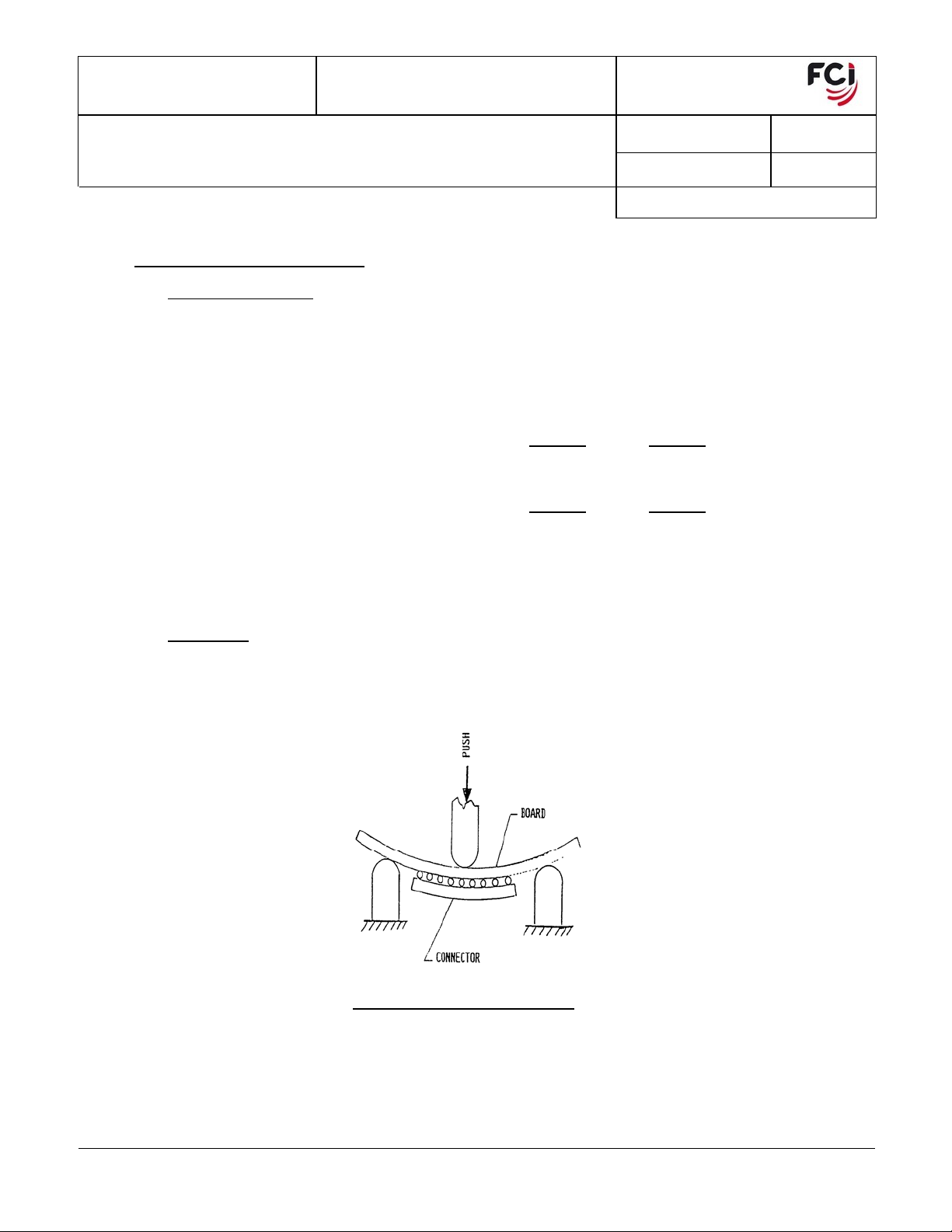
7.2 3-Point Bend
– The connectors are soldered onto an 0.062” thick FR-4 bd. With pad geometry and footprint
per FCI Customer drawing and Application Specification GS-20-016. The board is fixtured and bowed 20 mils/inch
of board support distance (see Figure 3). Dye penetrant is applied to solder joints and
off board and solder joints are visually inspected for cracks that occurred during bending. Per BUS-19-
125 3-Point Bend Procedure.
- Both plug and receptacle shall be soldered onto boards and the boards held in place
AUTHORIZED BY DATE
CLASSIFICATION
200 Pos. 296 Pos.
200 Pos. 296 Pos.
8 of 15 G
D. Harper 20 OCT 07
UNRESTRICTED
dried. Connector is pried
Copyright FCI
Form E-3334
Rev F
FIGURE 3 – 3-Point Bend Test
PDM: Rev:G Released .STATUS: Printed: Oct 23, 2007
GS-01-001
Page 9

NUMBER
GS-12-192
TYPE
PRODUCT SPECIFICATION
TITLE PAGE REVISION
GIG-ARRAY® High Speed Mezzanine Connectors
15-35 mm Board to Board
AUTHORIZED BY DATE
CLASSIFICATION
7.3 Contact Normal Force – Prior to test, measure contact overlap (CO) and calculate total contact deflection TCD
= CO + 0.20 mm. When contact tines are deflected TCD mm and tested in accordance with BUS-03-404, the
contact normal force shall be greater than 50 grams initial and 40 grams final. To expose contacts, receptacle
connectors shall have cover removed prior to testing. Contacts will be tested in pairs, 1S-8S as shown in
figure 4. Two wafers per connector (16 pairs) shall be tested.
9 of 15 G
D. Harper 20 OCT 07
UNRESTRICTED
Copyright FCI
Form E-3334
Rev F
FIGURE 4 Contact Normal Force Test
PDM: Rev:G Released .STATUS: Printed: Oct 23, 2007
GS-01-001
Page 10

NUMBER
GS-12-192
TYPE
PRODUCT SPECIFICATION
TITLE PAGE REVISION
GIG-ARRAY® High Speed Mezzanine Connectors
15-35 mm Board to Board
ENVIRONMENTAL CONDITIONS
After exposure to the following environmental conditions in accordance with the specified test procedure and/or
details, the product shall show no physical damage and shall meet the electrical and mechanical requirements as
specified in the Table 1 test sequence. Unless specified otherwise, assemblies shall be mated during exposure.
8.1. Temperature Cycling
a) Number of samples- 30 mated pair
b) Temperature Range – Between 0 and 100 ± 5°C. Temperature shall be measured and recorded
with a thermocouple mounted on the board as close as possible to the center of the ball pattern.
c) Temperature ramp < 20°C/minute (<10°C/minute preferred).
d) Dwell at each temp extreme- 15 minutes min. after PCB reaches temperature.
e) Time for Each Cycle – approx. 60 minutes (24 test cycles per day)
f) Connectors will be tested until 63.2% of the connectors (18 connectors) have failed or until 2670
cycles have been completed.
g) Any measured resistance exceeding 100% increase in total resistance from initial value (recorded at
hot temperature), shall be considered an open. An open followed by ten additional opens shall be
considered a failure. The time to failure shall be recorded as the first open cycle of the failure
sequence.
8.2 Humidity/Temperature Cycling – EIA-364-31, Method III exception 10-hour cycle.
Connectors shall be tested at elevated humidity and temperature shall be varied as specified below.
a) Relative Humidity 95%
b) Temperature range between +25°C and +65°C
c) Exclude steps 7A and 7B
d) Temperature ramp 1 hour/transition
e) Temperature dwell 3 hours minimum at +65°C
f) Time for each cycle- approx. 10 hours
g) Number cycles – 50 ( 500 hour test)
h) Connectors shall be mated.
8.3 High Temperature Life
a) Test Temperature – 85 °C
b) Test Duration – 500 hours
8.4 Thermal Shock-
A minimum of 3 connectors shall be mated and monitored for event detection > 1 microsecond.
a) Temperature range between -55°C and +85°C
b) Temperature transfer rate, < 1 minute
c) Temperature dwell, 30 minutes at each temperature extreme
d) Number cycles, 5
e) Connectors shall be mated.
– Samples can be one or more nets wired in series.
– EIA-364-17
EIA-364-32
AUTHORIZED BY DATE
CLASSIFICATION
10 of 15 G
D. Harper 20 OCT 07
UNRESTRICTED
Copyright FCI
Form E-3334
Rev F
GS-01-001
PDM: Rev:G Released .STATUS: Printed: Oct 23, 2007
Page 11

NUMBER
GS-12-192
TYPE
PRODUCT SPECIFICATION
TITLE PAGE REVISION
GIG-ARRAY® High Speed Mezzanine Connectors
15-35 mm Board to Board
8.5 Corrosive Atmosphere – EIA-364-65 (Serial Method)
After initial LLCR and 50% durability cycles, connectors will be broken into two groups of five. The plugs from
the first group and the receptacles from the second group, shall be placed in the chamber unmated for 10
days. After 5 days unmated exposure, mate and recheck LLCR, then unmate and finish initial 10 days. Mate,
recheck LLCR and then leave in chamber for 10 days mated. After 5 days mated exposure, recheck LLCR,
and then return to chamber for final 5 days mated exposure.
Connectors shall be mounted to the appropriate printed wiring board(s) and exposed to mixed gas
atmosphere in the test chamber of a sufficient volume to result in saturation of the test chamber.
a) Relative humidity: 70% ± 2%
b) Exposure Time: 2 x 5 days, with both plug and receptacle run concurrently.
c) Temperature: 30° C ± 1º C
d) Average Corrosion Rate: 15 ± 3 micrograms per sq. cm-day
e) Gas Parameters: 200 ± 50 ppb NO
8.6 Durability – EIA 364-09
The connector pairs shall be mated/unmated 25 times total. The first 13 cycles are performed prior
to specific environmental test in the sequence. The remaining 12 cycles are performed after
environmental test. The test shall be performed with plug and receptacle soldered to board.
8.7 Mechanical Vibration:
EIA-364-28
Five connectors shall be monitor for event detection > 1 microsecond.
a) Type: Sinusoidal, 10 to 500 Hz, 10g (Total frequency traverse time 15 min.)
b) Direction: Along each of three mutually perpendicular axis.
c) Time: 8 hours per axis (24 hours total)
d) After completion of test in all three axis, connector shall meet post environmental LLCR
requirement.
8.8 Mechanical Shock:
EIA-364-27
Five connectors shall be monitor for event detection > 1 microsecond.
a) Type: 30g, 11 ms pulse duration, ½ Sine
b) Direction: In each of three mutually perpendicular planes
c) Number: 3 shocks per axis (18 total shocks)
d) After completion of test in all three axis, connector shall meet post environmental LLCR
requirement.
AUTHORIZED BY DATE
, 10 ± 5 ppb H2S, 10 ± 3 ppb CL2, 100 ± 20 ppb SO2
2
CLASSIFICATION
11 of 15 G
D. Harper 20 OCT 07
UNRESTRICTED
Copyright FCI
Form E-3334
Rev F
GS-01-001
PDM: Rev:G Released .STATUS: Printed: Oct 23, 2007
Page 12

NUMBER
GS-12-192
TYPE
PRODUCT SPECIFICATION
TITLE PAGE REVISION
GIG-ARRAY® High Speed Mezzanine Connectors
15-35 mm Board to Board
8.9 Dust: EIA-364-91
Where specified in test sequence, connectors shall have dust applied to unmated interfaces.
a) Use dust composition #1 Benign
b) Use 9 g dust / each ft
c) Dry dust for 1 hour at 50°C prior to application to connector.
d) Connector shall have dust exposure for 1 hour at 300 cfm flow rate.
e) After exposure, let connectors sit for 1 hour in chamber.
8.10 Disturbed Interface
After exposure to MFG and post LLCR measurement, connector interface shall be disturbed so
that contact surfaces move about 0.10mm (.004 inches) or less.
9.0 QUALITY ASSURANCE PROVISIONS
9.1 Equipment Calibration
All test equipment and inspection facilities used in the performance of any test shall be maintained
in a calibration system in accordance with ANSI/NCSL Z-540-1
9.2 Inspection Conditions
Unless otherwise specified herein, all inspections shall be performed under the following ambient
Conditions:
a) Temperature: 25 ± 5° C.
b) Relative Humidity: 30% to 60%
c) Barometric pressure: Local ambient
9.3 Sample Quantity And Description
Refer to Table 1 for sample quantity.
Test group 1 requires connector pairs terminated to LLCR PCB.
Test group 2 requires five connector pairs terminated to LLCR PCB and a minimum of three
connector pairs terminated to continuity PCB.
Test group 3 requires loose piece connector pairs.
Test group 4 requires five connector pairs terminated to LLCR PCB and a minimum of three
connector pairs terminated to continuity PCB. Mated connectors shall be held
together with standoffs and fasteners.
Test group 5 requires connector pairs terminated to 0.062” minimum thickness LLCR PCB.
Test group 6 requires loose piece connectors.
Test group 7 requires connectors terminated to continuity PCB. Mated connectors shall be held
together with standoffs and fasteners.
Test group 8 requires connector pairs terminated to 0.062” nominal thickness PCB.
Test group 9 requires connector pairs terminated to special serial current test PCB.
Test group 10 requires connector pairs terminated to special high-speed test PCB.
3
of test chamber space
:
AUTHORIZED BY DATE
CLASSIFICATION
12 of 15 G
D. Harper 20 OCT 07
UNRESTRICTED
Copyright FCI
Form E-3334
Rev F
GS-01-001
PDM: Rev:G Released .STATUS: Printed: Oct 23, 2007
Page 13

NUMBER
GS-12-192
TYPE
PRODUCT SPECIFICATION
TITLE PAGE REVISION
GIG-ARRAY® High Speed Mezzanine Connectors
15-35 mm Board to Board
9.4 Acceptance
9.4.1 Electrical and mechanical requirements placed on test samples as indicated in
paragraphs 6.0 and 7.0 shall be established from test data using appropriate statistical
techniques or shall otherwise be customer specified, and all samples tested in
accordance with this product specification shall meet the stated requirements.
9.4.2 Failures attributed to equipment, test set-up or operator error shall not disqualify the
product. For failures attributed to the product, corrective action shall be taken and
samples resubmitted for qualification.
9.5 Qualification Testing
Qualification testing shall be performed on sample connectors produced with equipment and
procedures normally used in production. The test sequence shall be as shown in Table 1.
9.6 Requalification Testing
If either of the following conditions occur, the responsible Product Engineer shall initiate
requalification testing consisting of all applicable parts of qualification test matrix, Table 1.
(a) A significant design change is made to existing product, which impacts product form, fit or
function. Examples include, but shall not be limited to, changes in plating material,
composition or thickness, contact force, base material or interface geometry, housing
material or design or solder composition.
(b) A significant change is made to the product manufacturing process, which impacts the
product form, fit or function.
(c) A significant event occurs during production or end use requiring corrective action to be
taken relative to the product design or manufacturing process.
AUTHORIZED BY DATE
CLASSIFICATION
13 of 15 G
D. Harper 20 OCT 07
UNRESTRICTED
Copyright FCI
Form E-3334
Rev F
GS-01-001
PDM: Rev:G Released .STATUS: Printed: Oct 23, 2007
Page 14

NUMBER
8,9,78,9,99
4
GS-12-192
TYPE
PRODUCT SPECIFICATION
TITLE PAGE REVISION
GIG-ARRAY® High Speed Mezzanine Connectors
15-35 mm Board to Board
TEST GROUP
3
2,7
3
TEST SEQUENCE
26,4,6,8,10,
12
2,6
3,7
1,6
3
45
7
7
9
2,7
,11
TEST PARA. 1 2
Examination of P roduct
Contact Resistance Low
Level
Insulation Resistance
5.4
6.1
6.2
1,17 1,13 1,8 1,13 1,7 1,5 1,3 1,3 1,3 1
6
,4,6,8,10,
2
12,14,16
26,4,6,8,10,
7
12
7
Dielectric Withstandin g
Voltage
Current Rating
Propagation Delay
6.3
6.4
6.6
Characteristic
Impedance
Crosstalk
Diff Eye Pattern
Mating/Unmating Force
Contact Norm al Force
Mechanical Vibration
Mechanical Shock
3-point B e nd
Temperature Cycling
Therm al Shock
Temperature-Humidity
Hi Temperature Life
Durability
Corrosive Atmosphere
Dust
Disturbed In terface
6.7
6.8
6.10
7.1
7.3
8.7
8.8
7.2
8.1
8.4
8.2
8.3
8.6
8.5
8.9
8.10
34
95
1,6
2,7
,15
3
5
9
11
1,6
5
,11
,
75
13
Qty. Conn Pair/Group 10 8 2 10 5 3
Notes:
1. First 50% of the total number of specified durability cycles.
2. Second 50% of the total number of specified durability cycles.
3. Except for during IR and DWV measurements, connector pairs are unmated.
4. Only receptacle connectors are to be tested in this group. Mate with standard plug, or to simulate mated condition, mate with 0.20±.
0.013 mm thick copper plate during Hi Temp. Life.
5. Prior to application of dust, precondition connectors with first 50% of the total number of specified durability cycles.
6. Record LLCR after first mate.
7. Record LLCR prior to last unmate.
8. For initial 10 days, connectors are unmated in MFG chamber.
9. Expose in 5-day increments.
AUTHORIZED BY DATE
CLASSIFICATION
3,5
2,6
43
TABLE 1 – QUALIFICATION TESTING SEQUENCE
14 of 15 G
D. Harper 20 OCT 07
UNRESTRICTED
4
6
2,4
78910
2
2
2
30321
2
3
4
5
Copyright FCI
Form E-3334
Rev F
GS-01-001
PDM: Rev:G Released .STATUS: Printed: Oct 23, 2007
Page 15

NUMBER
GS-12-192
TYPE
PRODUCT SPECIFICATION
TITLE PAGE REVISION
GIG-ARRAY® High Speed Mezzanine Connectors
15-35 mm Board to Board
AUTHORIZED BY DATE
CLASSIFICATION
REVISION RECORD
REV PAGE DESCRIPTION EC # DATE
A All Initial Release V21483 9/10/2002
B Added additional “new” 200 position size and new heights V03-0917 9/29/2003
Changed 200 Pos. withdraw force from 4.8 kgms to 4.0 kgms on
page 7. Also changed the Qualification table on page 14 to reflect
the actual testing of the qualification test. Revision B had the
C 7&14
incorrect table attached. V04-0284 3/24/2004
D 2&3 Add part numbers; 10055143 and 10055142 V05-1058 11/17/05
Lead Free additions and 25mm Plug information added
E
Diff Eye Pattern replaced Rise time testing, document error V06-0083 2/10/06
F All Change logo V06-0539 6/5/2006
G
8
Changed 7.1 Max. mating forces to Average and Min un-mating.
5
1-2
Changed 6.4 to add 3 contact power rating
Updated 4.1 drawing numbers V07-0618 10/20/2007
15 of 15 G
D. Harper 20 OCT 07
UNRESTRICTED
Copyright FCI
Form E-3334
Rev F
GS-01-001
PDM: Rev:G Released .STATUS: Printed: Oct 23, 2007
 Loading...