

Page 1
GP1F31T/R, GP1F32T/R, GP1F33TT/RR/RT, GP1C331/331A/335
GP1F31T/R, GP1F32T/R,
Light Transmitting
/Receiving Units
GP1F33TT/RR/RT,
GP1C331/331A/335
■Features
1. Low jitter (∆
tj:TYP. 1ns
2. High speed signal transmission
(8Mbps, NRZ signal
3. Directly connectable to modulation
/demoduration IC for digital audio equipment
•Light transmitting unit••• Built-in light
emitting diode driving circuit
•Light receiving unit••• Built-in signal proce-
ssing circuit
4. With two fixing holes for easy mounting
on set panel
GP1F32T/GP1F32R/GP1F33
()
GP1F33TT/33RT
5. 2-channel type
(GP1F33RR/GP1F33TT/GP1F33RT
∗ We recommend you to use Sharp's optical fiber
(
cable, , GP1C331A,
GP1C331
)
)
RR
/
)
GP1C335
)
■Applications
1. CD players
2. BS tuners
3. Digital amplifiers
■Model Line-ups
Model No.
GP1F31T
GP1F31R
GP1F32T
GP1F32R
GP1F33TT
GP1F33RR
GP1F33RT
GP1C331
GP1C331A
GP1C335
Light transmitting unit
Light receiving unit
Light transmitting unit
Light receiving unit
Dual light transmitting unit
Dual light receiving unit
Light transmitting&receiving units
Optical fiber cable (1m
Optical fiber cable (0.6m
Optical fiber cable (5m
Internal Constitution
)
)
)
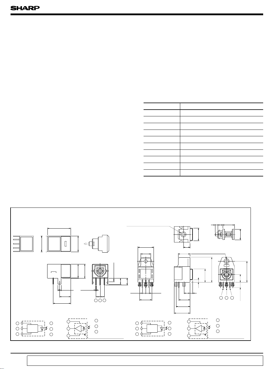
■Outline Dimensions
GP1F31T/GP1F31R GP1F32T/GP1F32R
φ2.5 fixing hole φ4
1.6
3.6
Depth 8.0
)
3.6
(
2.54
9.5
1
Vin
2
V
CC
3 GND
5
φ2.5 fixing hole φ4
9
1.9
2
4.6
8.5
10.6
12
Detector IC
1
Amp.
3
2
12
7.6
2.54
9.2
Driver
IC
LED
2
1
3
±0.5
14
)
9.5
Shield case sec.
(
2
6.7
10.53
GP1F31T GP1F31R GP1F32T
2
1
3
∗ OPIC is a trademark of Sharp and stands for Optical IC.
It has light detecting element and signal processing circuitry integrated single chip.
LED
Driver
IC
“In the absence of confirmation by device specification sheets, SHARP takes no responsibility for any defects that occur in equipment using any of SHARP's devices, shown in catalogs,
data books, etc. Contact SHARP in order to obtain the latest version of the device specification sheets before using any SHARP's device.”
1 Vin
2 V
CC
3 GND
Protection cap
)
9.58.2
Resin sec.
(
8.5
0.5
2-2.54
23
1
Detector IC
1 V
1
Amp.
3
2
CC
2 GND
3 Vout
*
OPIC light detector
(
Unit:mm
Protection cap
19
10.1
123
GP1F32R
1 V
2 GND
3 Vout
*
OPIC light detector
93.782
CC
)
16
6
4
Page 2

GP1F31T/R, GP1F32T/R, GP1F33TT/RR/RT, GP1C331/331A/335
■ Outline Dimensions
GP1F33TT/GP1F33RR
GP1F33RT
φ 2.5 fixing hole φ 4
Depth 7.2
14.0
6.0
PPPP
9.2 9.2
27.2
P =2.54
(
Lead root dimension
Optical fiber cable (GP1C331
MAX
0.2
4 231
9.5
30.5
16
4
45.5
JAPAN
5.8
12.0
)
)
2.0 3.7 9.0
5.0
9.0
1.6
4.6
8.5
L=1000
φ2.2
Protection cap
19.0
11.8
1.9 8.2
2.0
+100
- 0
8.0
φ 2.6 fixing hole φ 4
3
2
1
JAPAN
18.0
30.0
4
5
VIEW A 2/1
VIEW A
(
Unit : mm
)
Terminal arrangement
GP1F33TT
1 , 4 Vin
2,5 V
CC
3 , 6 GND
Transmitting portion
0.1µ F
LED
LED ; GaAlAs
Drive IC ; silicon
Internal equivalent circuit
16.0
6.0
± 0.5
4
6
4-C2
6
OPIC light detector
1 V
2 GND
3 Vout
Receiving portion Transmitting portion
Receiver
OPIC light detector
11±0.7
6
4.4
4.4
2.6 2-C1.12-C1.25
2
Drive
1
IC
3
GP1F33RR
1,4 V
2,5 GND
3,6 Vout
Receiving portion
0.1µ F
4.7µ F
1
3
2
GP1F33RT
CC
0.1µ F
4.7µ F
1
3
2
Model No.
1.62
GP1C331
GP1C331
9.3±0.7
GP1C331
CC
OPIC light detector
0.1µ F
LED
Drive
IC
LED ; GaAlAs
Drive IC ; silicon
0.1µF
4 Vin
5 V
CC
6 GND
Transmitter
0.1µ F
LED
Drive
IC
LED ; GaAlAs
Drive IC ; silicon
❈Dimensions
1 000
600
5 000
5
4
6
4.7µF
5
4
6
4
5
6
■ Absolute Maximum Ratings
Supply voltage V
Input voltage
Power dissipation
∗1
High level output current
∗2
Low level output current
Operating temperature
Storage temperature T
∗3
Soldering temperature T
∗1 Source current
∗2 Sink current
Fiber cable
Tension
Bending radius R 25 Min. mm
Operating temperature T
Storage temperature
Parameter Symbol Ratings Unit
∗4
∗4
∗5
∗5
∗6
∗7
∗3 5 seconds/time up to 2 times
∗4 GP1F31T/GP1F32T/GP1F33TT/Transmitting portion of GP1F33RT
∗5 GP1F31R/GP1F32R/GP1F33RR/Receiving portion of GP1F33RT
∗6 GP1F31T/GP1F31R
∗7 GP1F32T/GP1F32R/GP1F33TT,GP1F33RR,GP1F33RT
(
GP1C331, GP1C331A, GP1C335
CC
V
in
P
I
OH
I
OL
T
opr
stg
sol
)
Parameter Symbol Rating Unit
Plug & optical fiber
Optical fiber T
T
pf
f
opr
T
stg
40
40
- 30 to + 70 ˚C
- 30 to + 70 ˚C
(Ta= 25˚C)
- 0.5 to + 7 V
- 0.5 to VCC+ 0.5
125 mW
4mA
4mA
- 10 to + 60
260 ˚C
N
N
V
˚C
˚C- 20 to + 70
˚C- 30 to + 80
Page 3
GP1F31T/R, GP1F32T/R, GP1F33TT/RR/RT, GP1C331/331A/335
■ Electro-optical Characteristics
(1)
Transmitter
(
GP1F31T/GP1F32T/GP1F33TT/ Transmitting portion of GP1F33RT
Parameter Symbol MIN. TYP. MAX. Unit
Operating voltage V
Peak emission wavelength λ
Fiber coupling light output P
Dissipation current
High level input voltage V
Low level input voltage V
“ Low→High” propagation delay time
“ High→Low” propagation delay time
Pulse width distortion ∗9
Jitter ∗10 - 1 25(30
CC
P
C
I
CC
IH
IL
t
PLH
t
PHL
∆
tw
∆
tj
Conditions
-
-
4.75 5.00 5.25 V
630 660 690 nm
∗7 - 21 - 17 - 15 dBm
∗8-
410mA
∗82--V
∗8 - - 0.8 V
∗9 - - 100 ns
∗9 - - 100 ns
∗∗
(
)
-
-
25
-
30
Ta = 25˚C
(
)
-
-
25
30
)
∗∗
∗∗
Operating transfer rate T ---8
∗∗ Value in parenthesis: GP1F31T
(2)
Receiver
(
GP1F31R/GP1F32R/GP1F33RR/Receiving portion of GP1F33RT
Parameter Symbol MIN. TYP. MAX. Unit
Operating voltage V
Peak sensitivity wavelength
Maximum input optical power level for receiving unit
Minimum input optical power level for receiving unit
Dissipation current I
High level output voltage V
Low level output voltage V
Rise time t
Fall time t
“ Low→High” propagation delay time
“ High→Low” propagation delay time
Pulse width distortion ∗13 - 30 - + 30 ns
Jitter
P
P
CC
λ
CMAX
CMIN
CC
OH
OL
r
f
t
PLH
t
PHL
∆
tw
∆
tj
P
Operating transfer rate T
Conditions
-
-
4.75 5.00 5.25 V
700 - nm
-
∗11 - 14.5 - - dBm
∗11 - - - 24 dBm
∗12 - 15 40 mA
∗13 2.7 3.5 - V
∗13 - 0.2 0.4 V
∗13 - 12 30 ns
∗13 - 4 30 ns
∗13 - - 100 ns
*13 - - 100 ns
∗14
PC= -15dBm
∗14
P
= -24dBm
C
NRZ.
duty 50% input
- 1 30 ns
- - 30 ns
0.1 - 8
Ta = 25˚C
)
ns
ns
Mbps
)
Mbps
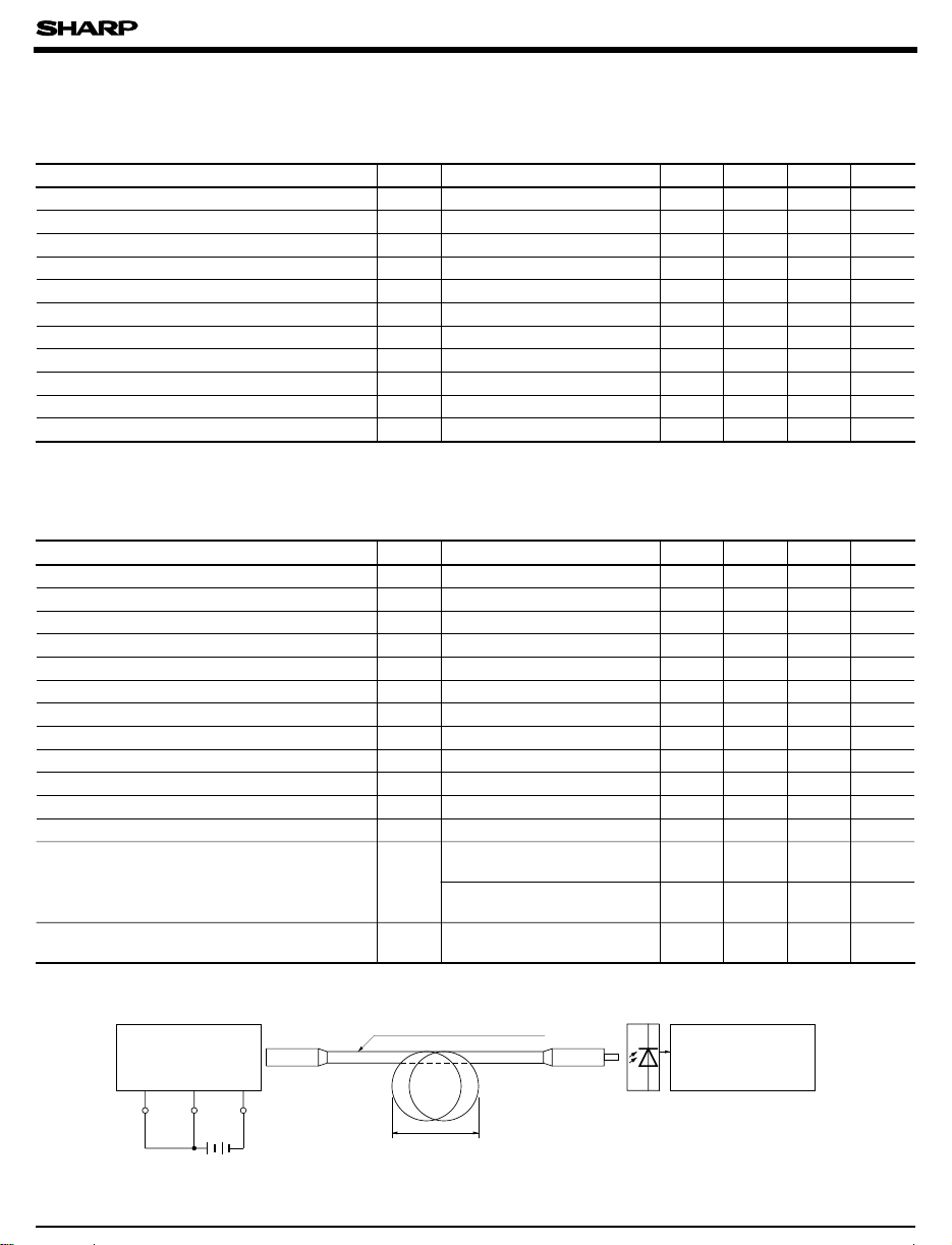
∗7 Measuring method of optical output coupling fiber
GP1F31T/GP1F32T/
GP1F33TT
Unit to be measured
Vin V
Note 1) V
2) To bundle up the standard fiber cable, make it into a loop with the diameter (D) of 10cm or more.
= 5.0 ± 0.05V(Operating
CC
GND
CC
V
CC
)
Standard optical fiber cable
D
The optical power meter must be calibrated
to have the wavelength sensitivity of
660nm.
(
0dBm= 1mW
)
Optical power
meter
(
Anritsu) ML93
Page 4

GP1F31T/R, GP1F32T/R, GP1F33TT/RR/RT, GP1C331/331A/335
∗8 Input voltage/power dissipation measuring method
GP1F31T/GP1F32T/
GP1F33TT/GP1F33RT
Sample
Vin GND
Vcc
Icc
Vin
V
CC
Standard fiber cable
Input condition and measuring method
Input condition Measuring method
Vin= 2.0V or more -21<= P
Vin= 0.8V or less P
Note (1) V
∗9 Pulse response measuring method
= 5.0± 0.05V (ON-State
CC
GP1F31T/GP1F32T/
GP1F33TT/GP1F33RT
Unit to be measured
Vin GND
Input
Input signal
Vcc
V
CC
6Mbps NRZ “1010” successive pattern
<= -15dBm, ICC=10mA or less
C
<= -36dBm, ICC=10mA or less
C
)
Standard optical fiber cable
Light power meter
(
Anritsu) ML93B
Light power meter should be
corrected to wavelength sensitivity (660nm
[ 0dBm= 1mW]
Standard
receiver
Output
signal
Oscilloscope
CH1
CH2
)
GP1F31T/GP1F32T
GP1F33TT/GP1F33RT
Input signal
(
)
CH1
Standard receiver
Output signal
(
)
CH2
Pulse width distortion ∆ tw= t - t
50%
Note 1) V
50%
t
PLH
t
PHL
PHL PLH
= 5.0 ±0.05V (Operating
CC
2) The probe for the oscilloscope must be
more than 1MΩ and less than 10pF.
)
Page 5

∗10 Jitter measuring method
GP1F31T/GP1F32T/
GP1F33TT/GP1F33RT
Unit to be measured
Vin GND
Vcc
Vcc
GP1F31T/R, GP1F32T/R, GP1F33TT/RR/RT,GP1C331/331A/335
Standard optical fiber cable
Standard
receiver
Output
signal
Input
1
1
Input signal
Standard receiver
output
Input signal 3Mbps
biphase mark PBRS signal
00
50%
CH1
CH2
)
The waveform write time shall be 4 seconds. But do
Note 1
Oscilloscope
Trigger: CH1 Storage mode
not allow the waveform to be distorted by increasing
the brightness too much.
)
V
2
50%
∆ tj∆ tj
3
=5.0 ±0.05V (Operating
CC
)
The probe for the oscilloscope must be more than
1MΩ and less than 10pF.
∗11 Maximum input optical power level/Minimum input optical power level measuring method of receiving unit
Standard
transmitter
)
Optical power meter must be calibrated to have
Note 1
the wavelength sensitivity of 660nm.
)
With no optical attenuator connected, use the
2
transmitter GP1F31T/GP1F32T/GP1F33TT and
Variable optical
attenuator
GP1F31R/GP1F32R
GP1F33RR/GP1F33RT
Unit to be measured
Optical power meter
Anritsu : ML93B
the optical fiber cable GP1C331 with the fiber
coupling light output set at -15dBm/ - 24dBm.
)
∗12 Dissipation current measuring method
Standard
transmitter
Vin GND
Vcc
Input
6Mbps NRZ, duty 50%
or 3Mbps biphase PRBS signal
Vcc
VCC= 5.0 ±0.05V
PC= -15dBm
Standard optical fiber cable
GP1F31R/GP1F32R
GP1F33RR/GP1F33RT
Unit to be measured
GND Vout
Vcc
(
DC average current value
Vcc
A
Ammeter
)
Page 6

GP1F31T/R, GP1F32T/R, GP1F33TT/RR/RT,GP1C331/331A/335
∗13 Output voltage/Pulse response mesuring method
Standard
transmitter
Vin Vcc GND
5V
Input
6Mbps NRZ, duty 50%
Standard optical fiber cable
GP1F31R/GP1F32R/
GP1F33RR/GP1F33RT
Unit to be measured
GND Vout
Vcc
Vcc
Rso
Rsi
CH1
CH2
Oscilloscope
Standard
transmitter
Input signal
(
)
CH1
GP1F31R/GP1F32R
GP1F33RR/GP1F33RT
Output signal
(
)
CH2
∗14 Jitter measuring method
GP1F31T/GP1F32T/
GP1F33TT
Transmitter
Input
1
1
Input signal
GP1F31R output
GP1F32R output
GP1F33RR output
GP1F33RT output
00
trt
V
OH
V
OL
t
PLH
GNDVccVin
5V
Input signal 3Mbps
biphase PBRS
∆ tj
f
t
PHL
Standard optical fiber cable
∆ tj
50%
50%
50%
90%
50%
10%
1) V
Notes
: 5.0 ±0.05V (Operating
CC
2) The probe for the oscilloscope must be more
than 1MΩ and less than 10pF.
, Rso; Standard load resistrance
3) R
si
: 3.3kΩ , Rso: 2.2kΩ
(R
si
GP1F31R/GP1F32R/
GP1F33RR/GP1F33RT
Unit to be measured
Vcc
Vcc
CH1
CH2
Notes 1) R
2
3
: Strandard load resistance
si Rso
(R
)
= 5.0 ± 0.05V (Operating
V
CC
)
Set the oscilloscope to be storage mode and
VoutGND
Rso
Rsi
Oscilloscope
Trigger : CH1
Storage mode
Sweep : AUTO/NORM
: 3.3Ω Rso: 2.2kΩ
si
write time to 3 seconds. Do not allow the
waveform to be distorted by icreasing the
brightness too much
)
The probe for oscilloscope must be more
4
than 1MΩ and less than 10pF.
)
)
)
)
Page 7

GP1F31T/R, GP1F32T/R, GP1F33TT/RR/RT,GP1C331/331A/335
(3)
Optical Fiber Cable
Parameter Symbol MIN. TYP. MAX. Unit
Optical output coupling fiber
Refracting ratio distribution
Measuring method for optical output coupling fiber
Standard optical fiber cable
Standard
transmitter
Standard light transmitter: Light transmitter that provides the fiber-end optical output of - 15dBm ±0.3dBm when
the standard optical fiber cable is connected.
- 17 - dBm
P
C
--
Step index
■ Mechanical Characteristics
Parameter Symbol Condition MIN. TYP. MAX. Unit
Inserting power
disconnecting power
In compliance with
-
Initial value when a square connector 6 40 N
is used.
EIAJ RC-5720
Optical
power meter
Anritsu
ML93B
-
■ System Configuration Example
CD/DAT/BS Tuner
PCM
signal
Modulation IC
(
)
LZ92F39
Drive
circuit
Light
emitter
Optical transmitting
unit
GP1F31T/
GP1F32T
Optical fiber cable
GP1C331
Digital Amp.
processing
Optical receiving
GP1F31R/GP1F32R
Demodulation
IC (LZ92F39
Signal
circuit
unit
)
PCM
signal
Page 8

GP1F31T/R, GP1F32T/R, GP1F33TT/RR/RT, GP1C331/331A/335
BS tuner Digital Amp.
PCM
Modulation IC
signal
Optical
transmitting
unit
GP1F33TT
PCM
Modulation IC
signal
(
LZ92F39
(
LZ92F39
)
Drive
circuit
Drive
circuit
)
Light
emitter
Light
emitter
Optical fiber cable
GP1C331
Optical fiber cable
Light
detector
Light
detector
Signal
processing
circuit
Signal
processing
circuit
Demodulation
IC (LZ92F39
Demodulation
IC (LZ92F39
GP1C331
∗LZ92F39 is Sharp's modulation/demodulation IC.
In addition, you can also choose the following system configuration according to your application.
GP1F33TT
GP1F33RT GP1F33RT
GP1C331
GP1C331
GP1F33RR
PCM
signal
)
Optical
receiving unit
GP1F32R
GP1F32R
PCM
signal
)
●
Please refer to the chapter “ Precautions for Use”
 Loading...